engine MITSUBISHI ECLIPSE 1993 Workshop Manual
[x] Cancel search | Manufacturer: MITSUBISHI, Model Year: 1993, Model line: ECLIPSE, Model: MITSUBISHI ECLIPSE 1993Pages: 57, PDF Size: 4.18 MB
Page 2 of 57
Partial BACKUPService Manual
.i’
GROUP INDEXNOSAl
LASER
TALON
1993
Volume-l
Engine, Chassis& Body
FOREWORDThis Service Manual has been prepared with the
latest service information available at the time of
publication. It is subdivided into various group
categories and each section contains diagnosis,
disassembly, repair, and installation procedures
along with complete specifications and tightening
references. Use of this manual will aid in properly
performing any
servicrng necessary to maintain or
restore the high levels of performance and reliabilitydesigned into these outstanding vehicles.
This BACKUP DSM manual IS to be used ONLY as a BACKUP. Please DO NOT REDISTRIBUTEWHOLE SECTIONS. This BACKUP was sold to you under the fact that you do indeed OWNa GENUINE DSM MANUAL. It CANNOT BE considered a REPLACEMENT (Unless your orlglnalmanual was lost or destroyed.)Please See
README.N or README.HTML for additional Information.
Thank you. G~mm~emymanual@hotma~l.com
CHRYSLER
CORPORATION
Chrysler Corporation reserves the right to make changes in design or tomake additions to or improvements in its products without imposingany obligations upon itself to install them on its products previouslymanufactured.Introduction and
Master
Troubleshooting.-I. . . . . . . . . . . . . . . . . . i
Lubrication and Maintenance . . . . . . . .El
Front Suspension. . . . . . . . . . . . . . . . . . . . . . . . . . . ..A..tiRear Axle
. . . . . . . . . . . . . . . . . . . . . . . . . . . . . . . . . . . . . . . . . . . . . ..~...
Service’ Brakes- Parking. . . . . . . . . . . . . . . . . . . . . . . . . . . . . . . . . . . . . .
Clutch. . . . . . . . . . . . . . . . . . . . . . . . . . . . . . . . . . . . . . . . . . . . . . . . . ..~.....
Cooling. . . . . . . . . . . . . . . . . . . . . . . . . . . . . . . . . . . . . . . . . . . . ..~.....~~..
Engine. . . . . . . . . . . . . . . . . . . . . . . . ..*..............................Intake and Exhaust
. . . . . . . . . . . . . . . . . . . . . . . . . . . . .Fuel System
‘,,, .*. . . . . . . . . . . . . . . . . . ..*........................4Propeller Shaft
..,.....,....,.................m.......
Rear Suspension.*........s........................
ManualSteering-po,er.h. . . . . . . . . . . . . . . . . . . . . . . . . . . . . . . . . . . ..$\
ManualiTransaxle-Automatic:. . . . . , . . . . . . . . . . . . . . r+:,
Wheels and Tires_. .;,:.;*&i. . . . . . . . . . . . . . . . . . . . . . ..&......
j 8 .A$: >
Body. . . . . . . . . . . . . . . . . . . . . . . . . . . . . . . . . . . . . . . . . . . . . . . . . . ..*...**...
Heater & Air CondjtJoning ..,.. ,.,. . . ...’
EmissionControlSystems1. . . . . . . . . . . . . .
0 1992 Mitsubishi)L-.”:
Printed in U.S.A.
Page 9 of 57
BRAKES - Service Adjustment Procedures5-51
2314A0454When new
When worn14G0017
1
14 LO169check the sliding coWsTm~3..“.W% ,Y :sleeve and guide pin-~I ._. ;;:i ‘.(3) In this condition, the other person should use a finger to
close the outlet part of the, master cylinder, and then the
first person should release the brake pedal.
(4) Steps (2) and (3) should be repeated three or four times,
and then the master cylinder should be filled with brake
fluid to the specified level.
NOTE
The air is completely bled from the master cylinder by steps
(1) to (4).
(5) Connect the brake tube to the master cylinder.
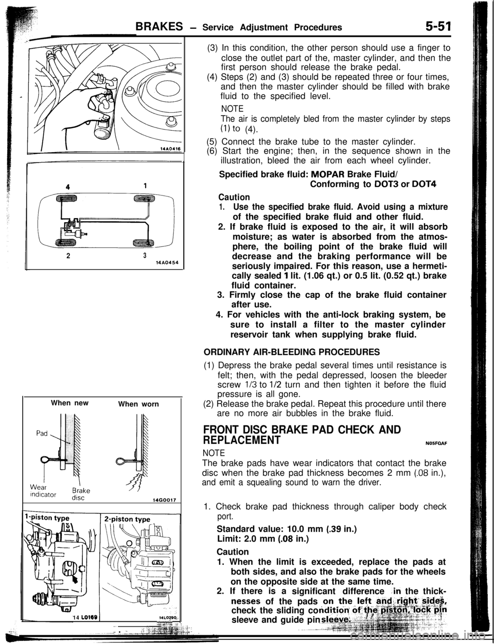
(6) Start the engine; then, in the sequence shown in the
illustration, bleed the air from each wheel cylinder.
Specified brake fluid: MOPAR Brake Fluid/
Conforming to
DOT3 or DOT4
Caution
1.Use the specified brake fluid. Avoid using a mixtureof the specified brake fluid and other fluid.
2. If brake fluid is exposed to the air, it will absorb
moisture; as water is absorbed from the atmos-
phere, the boiling point of the brake fluid will
decrease and the braking performance will be
seriously impaired. For this reason, use a hermeti-
cally sealed
1 lit. (1.06 qt.) or 0.5 lit. (0.52 qt.) brake
fluid container.
3. Firmly close the cap of the brake fluid container
after use.
4. For vehicles with the anti-lock braking system, be
sure to install a filter to the master cylinder
reservoir tank when supplying brake fluid.
ORDINARY AIR-BLEEDING PROCEDURES
(1) Depress the brake pedal several times until resistance is
felt; then, with the pedal depressed, loosen the bleeder
screw
l/3 to l/2 turn and then tighten it before the fluid
pressure is all gone.
(2) Release the brake pedal. Repeat this procedure until there
are no more air bubbles in the brake fluid.
FRONT DISC BRAKE PAD CHECK AND
REPLACEMENTN05FOAF
NOTEThe brake pads have wear indicators that contact the brake
disc when the brake pad thickness becomes 2 mm
(.08 in.),
and emit a squealing sound to warn the driver.1. Check brake pad thickness through caliper body check
port.Standard value: 10.0 mm
(.39 in.)
Limit: 2.0 mm
(.08 in.)
Caution
1. When the limit is exceeded, replace the pads at
both sides, and also the brake pads for the wheels
on the opposite side at the same time.
2. If there is a
significant difference
.in the thick-
nesses of the pads
Page 11 of 57
guiisur
dd
lght
clidc
Pad assembly
luter shim
nner shim
43l a14FOO97
14A0399
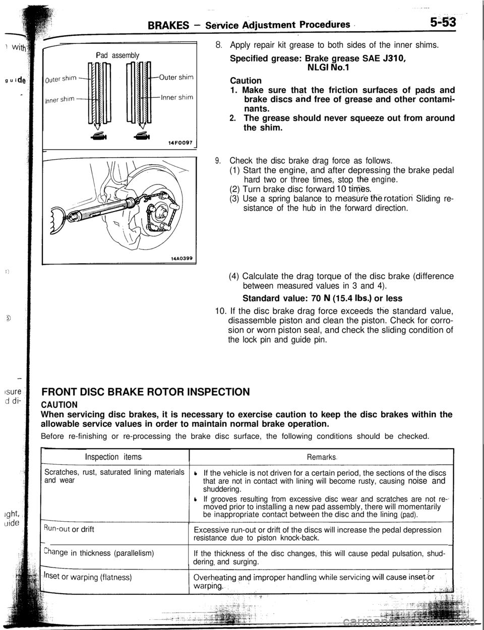
Apply repair kit grease to both sides of the inner shims.Specified grease: Brake grease SAE 5310,
NLGI No.1Caution
1. Make sure that the friction surfaces of pads and
brake discs and free of grease and other contami-
nants.
2.The grease should never squeeze out from around
the shim.
9.Check the disc brake drag force as follows.(1) Start the engine, and after depressing the brake pedal
hard two or three times, stop the(2) Turn brake disc forward
10 tie&.
engine.
(3) Use a spring balance to meastiie fh-e rotation Sliding re-
sistance of the hub in the forward direction.(4) Calculate the drag torque of the disc brake (difference
between measured values in 3 and 4).Standard value: 70
N (15.4 Ibs.) or less
10. If the disc brake drag force exceeds
tlie standard value,
disassemble piston and clean the piston. Check for corro-
sion or worn piston seal, and check the sliding condition of
the lock pin and guide pin.FRONT DISC BRAKE ROTOR INSPECTION
CAUTIONWhen servicing disc brakes, it is necessary to exercise caution to keep the disc brakes within the
allowable service values in order to maintain normal brake operation.
Before re-finishing or re-processing the brake disc surface, the following conditions should be checked.
Inspection itemsRemarks
Scratches, rust, saturated lining materials
and wearlIf the vehicle is not driven for a certain period, the sections of the discsthat are not in contact with lining will become rusty, causing noise and
shuddering.
lIf grooves resulting from excessive disc wear and scratches are not re-moved prior to installing a new pad assembly, there will momentarily
beinappropriatecontact between the disc and thelining(pad).
Run-out or drift
Ehange in thickness (parallelism)Excessive run-out or drift of the discs will increase the pedal depression
resistance due to piston knock-back.
If the thickness of the disc changes, this will cause pedal pulsation, shud-
deringand surging.
Page 14 of 57
BRAKES -Brake BoosterVacuum hose
14AO39414u0050Semidrvina sealant
141626Vacuum hose
IChevk valve
mm (in.)
14AO395
SERVICE PO@JTS OF REMOVALNocm6.
REM&AL OF VACUUM HOSE WITH CHECK VA+
NOTE
Since the check valve is fit to the vacuum hose, replace thcheck valve as an assembly unit together with the
vacuurhose if the check valve is defective.
SERVICE POINTS OF INSTALLATION
10. APPLDJTION OF GREASE TO CLEVIS PIN/g. WASHEIAfter applying the specified grease to the
clevis pin an
washer, insert the
cievis pin and bend the cotter pin tightlyGrease: MOPAR Multi-mileage Lubricant
Part No. 2525035 or equivalent
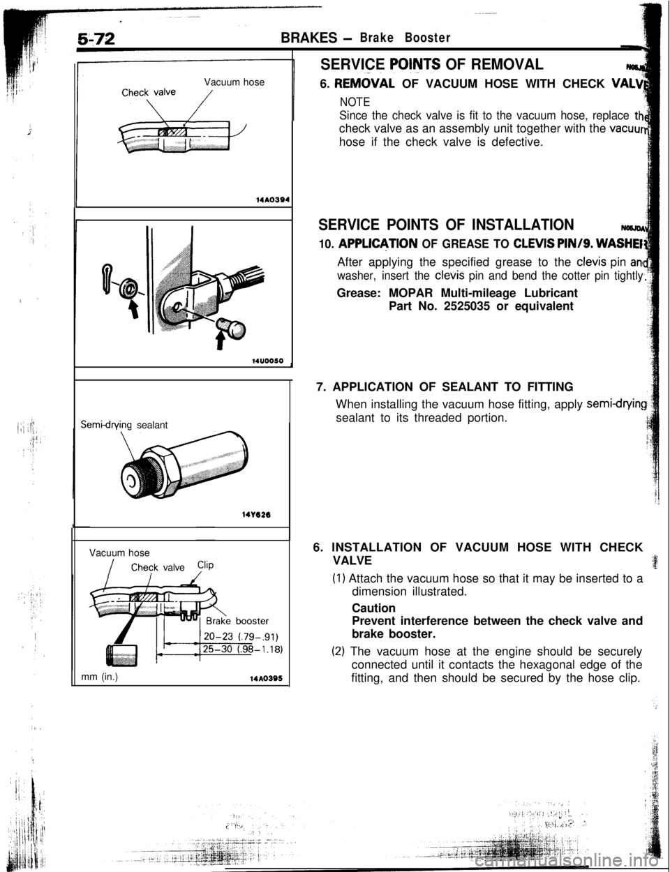
7. APPLICATION OF SEALANT TO FITTING
When installing the vacuum hose fitting, apply
semi-cfryin!sealant to its threaded portion.
6. INSTALLATION OF VACUUM HOSE WITH CHECK
VALVE
(1) Attach the vacuum hose so that it may be inserted to a
dimension illustrated.
Caution
Prevent interference between the check valve and
brake booster.
(2) The vacuum hose at the engine should be securely
connected until it contacts the hexagonal edge of the
fitting, and then should be secured by the hose clip.
Page 19 of 57
-
3AF
:dSERVICE POINTS OF INSTALLATION
NOBLDAG2.
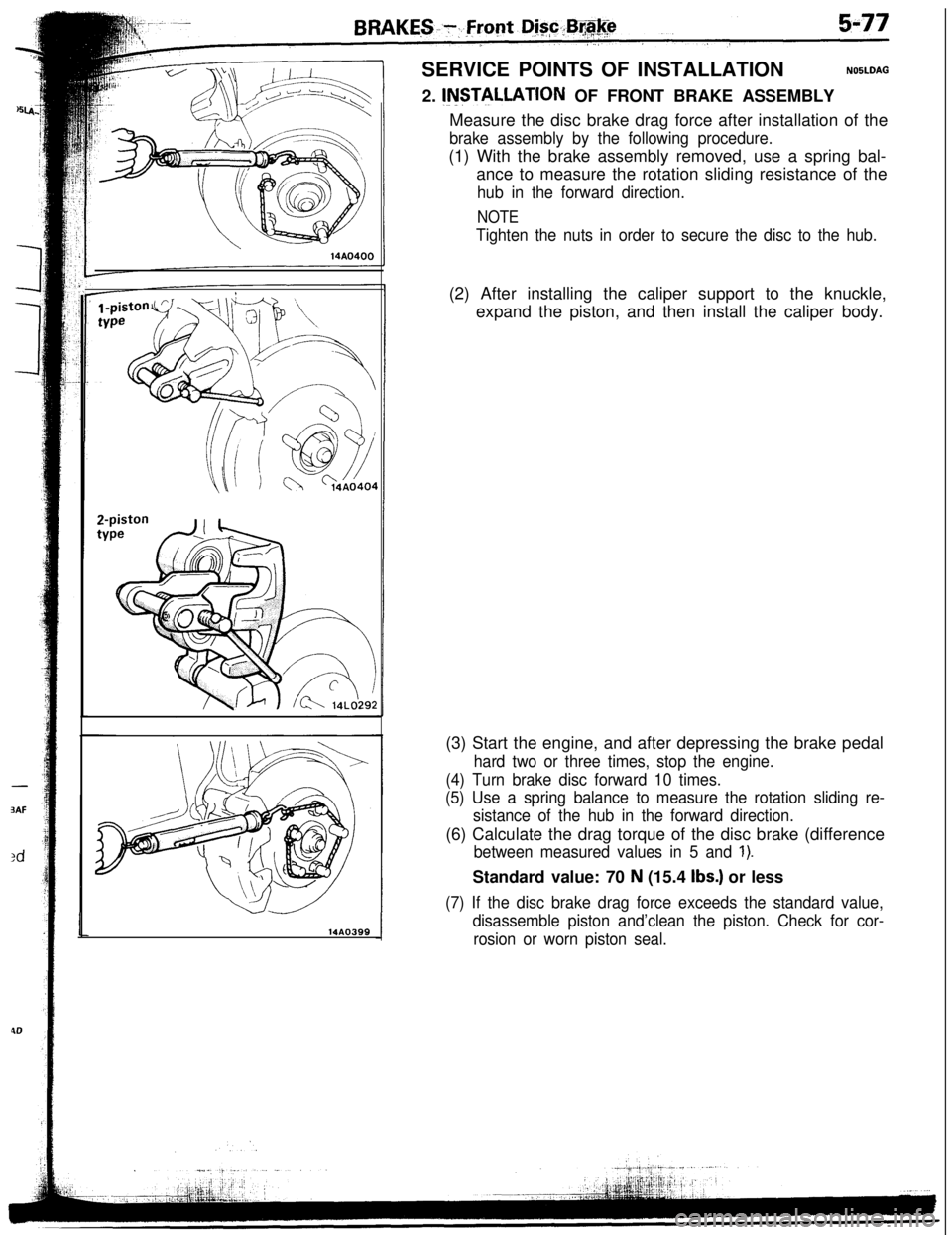
INSTILLATION OF FRONT BRAKE ASSEMBLY
14AO399Measure the disc brake drag force after installation of the
brake assembly by the following procedure.(1) With the brake assembly removed, use a spring bal-
ance to measure the rotation sliding resistance of the
hub in the forward direction.
NOTE
Tighten the nuts in order to secure the disc to the hub.(2) After installing the caliper support to the knuckle,
expand the piston, and then install the caliper body.
(3) Start the engine, and after depressing the brake pedal
hard two or three times, stop the engine.
(4) Turn brake disc forward 10 times.
(5) Use a spring balance to measure the rotation sliding re-
sistance of the hub in the forward direction.(6) Calculate the drag torque of the disc brake (difference
between measured values in 5 and 1).Standard value: 70
N (15.4 Ibs.) or less
(7) If the disc brake drag force exceeds the standard value,
disassemble piston and’clean the piston. Check for cor-
rosion or worn piston seal.