height MITSUBISHI ECLIPSE 1993 Workshop Manual
[x] Cancel search | Manufacturer: MITSUBISHI, Model Year: 1993, Model line: ECLIPSE, Model: MITSUBISHI ECLIPSE 1993Pages: 57, PDF Size: 4.18 MB
Page 6 of 57

-
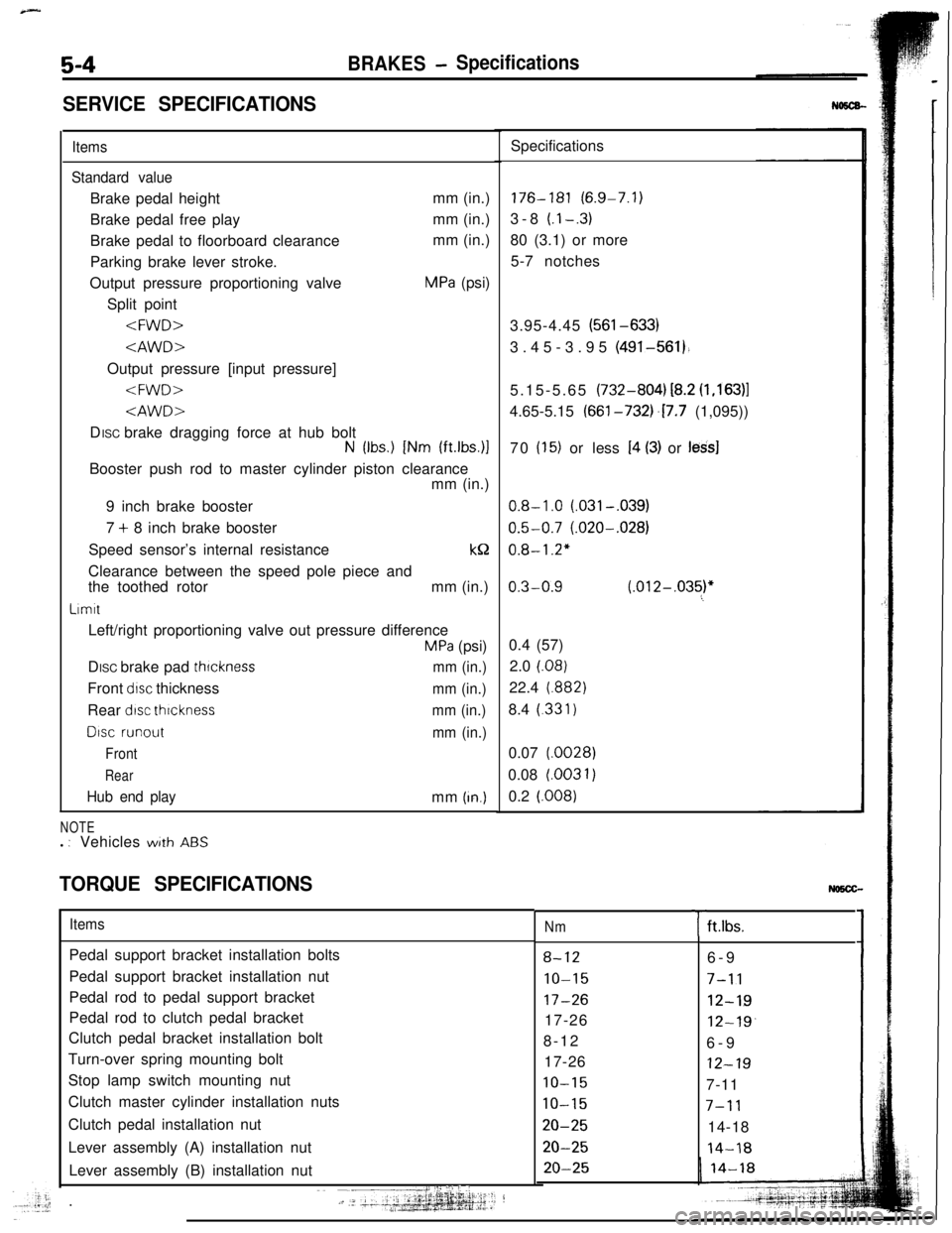
5-4BRAKES- Specifications
SERVICE SPECIFICATIONS
Items
Standard valueBrake pedal heightmm (in.)
Brake pedal free playmm (in.)
Brake pedal to floorboard clearancemm (in.)
Parking brake lever stroke.
Output pressure proportioning valve
MPa (psi)
Split point
N (Ibs.) [Nm (ft.lbs.)lBooster push rod to master cylinder piston clearance
mm (in.)
9 inch brake booster
7 + 8 inch brake booster
Speed sensor’s internal resistancek&
Clearance between the speed pole piece and
the toothed rotormm (in.)
LrmttLeft/right proportioning valve out pressure difference
MPa (psi)
DISC brake pad
thrcknessmm (in.)Front
drsc thicknessmm (in.)Rear
dtsc thrcknessmm (in.)
DISC runout
mm (in.)
Front
Rear
Hub end playmm (In.)
NOTEl : Vehicleswith ABS
TORQUE SPECIFICATIONSSpecifications176-181 (6.9-7.1)
3-8
(.l-.3)80 (3.1) or more
5-7 notches
3.95-4.45 (561-633)
3.45-3.95 (491-561).
5.15-5.65 (732-804) i8.2
(1,163)14.65-5.15 (661-732j.17.7 (1,095))
70
(15) or less I4 (3) or less]
0.8-1.0 (.031-,039)
0.5-0.7 (.020-.028)
0.8-1.2"
0.3-0.9 (.012-,035)"60.4 (57)
2.0
(.08)22.4
(.882)8.4
(.331)0.07
(.0028)0.08 l.0031)
0.2
(.008)
ItemsPedal support bracket installation bolts
Pedal support bracket installation nut
Pedal rod to pedal support bracket
Pedal rod to clutch pedal bracket
Clutch pedal bracket installation bolt
Turn-over spring mounting bolt
Stop lamp switch mounting nut
Clutch master cylinder installation nuts
Clutch pedal installation nut
Lever assembly (A) installation nut
Lever assembly (B) installation nut
I:: ::I .:‘i j ,:~~ -__j.-, .‘- ‘+‘+gg&p.~j:;.;1--?.+.k
Nm
8-12
IO-15
17-2617-26
8-12
17-26
10-15
10-15
20-25
20-25
20-25
Tft.lbs.
6-9
7-11
12-19
12-19.6-9
12-197-11
7-1114-18
14-18
Page 25 of 57

BRAKES 7 Front Disc Brake5-83
14AO55314A0552
\Piston seal\
14AO551
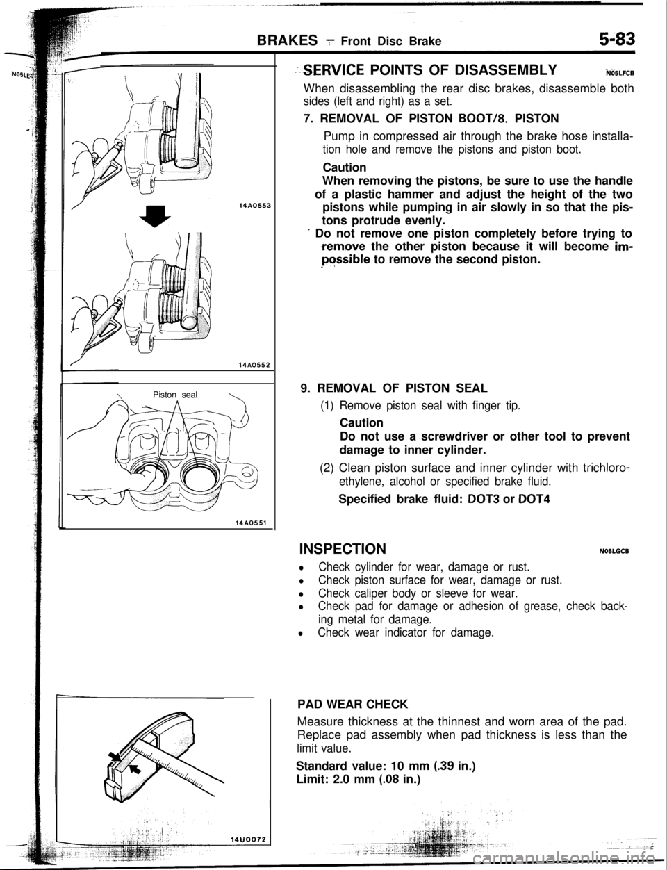
--SERVICE POINTS OF DISASSEMBLYiUO5LFCBWhen disassembling the rear disc brakes, disassemble both
sides (left and right) as a set.7. REMOVAL OF PISTON
BOOT/8. PISTON
Pump in compressed air through the brake hose installa-
tion hole and remove the pistons and piston boot.Caution
When removing the pistons, be sure to use the handle
of a plastic hammer and adjust the height of the two
pistons while pumping in air slowly in so that the pis-
tons protrude evenly.
I Do not remove one piston completely before trying to
,remove the other piston because it will become im-Possible to remove the second piston.
9. REMOVAL OF PISTON SEAL
(1) Remove piston seal with finger tip.Caution
Do not use a screwdriver or other tool to prevent
damage to inner cylinder.
(2) Clean piston surface and inner cylinder with trichloro-
ethylene, alcohol or specified brake fluid.Specified brake fluid:
DOT3 or DOT4INSPECTION
NOSLGCB
lCheck cylinder for wear, damage or rust.
lCheck piston surface for wear, damage or rust.
lCheck caliper body or sleeve for wear.
lCheck pad for damage or adhesion of grease, check back-
ing metal for damage.
lCheck wear indicator for damage.PAD WEAR CHECK
Measure thickness at the thinnest and worn area of the pad.
Replace pad assembly when pad thickness is less than the
limit value.Standard value: 10 mm
(.39 in.)
Limit: 2.0 mm
(.08 in.)