light MITSUBISHI ECLIPSE 1993 Workshop Manual
[x] Cancel search | Manufacturer: MITSUBISHI, Model Year: 1993, Model line: ECLIPSE, Model: MITSUBISHI ECLIPSE 1993Pages: 57, PDF Size: 4.18 MB
Page 32 of 57
INSTRUCTIONS FOR ALUMINUM TYPE
WHEELSN2zGFM
1. Aluminum is vulnerable to alkalies. If a vehicle
washing detergent has been used, or salt from
sea water or road chemicals has adhered, washthe vehicle as soon as possible. After washing
the vehicle, apply body or wheel wax to the
aluminum type wheels to prevent corrosion.
2. When cleaning the vehicle with steam, do not
direct steam onto the aluminum type wheels.
When tightening nuts for aluminum type
wheels, particularly observe the following:
(1) Cl;Zl;lsthe hub surface of aluminum type
(2) After finger-tightening wheel nuts, tighten
them to specifications.
(3) Do not use an impact wrench or push the
wrench by foot to tighten the wheel nuts.
(4) Do not apply oil to the threaded portions.
INSTRUCTIONS FOR TIRE CHAINS AND
SNOW TIRES
1.Use tire chains only on front wheels. Do not usetire chains on rear wheels.
2. When using snow tires, use them on all four
wheels for maneuverability and safety.
INSTRUCTIONS FOR COMPACT
TIRE
1. The compact spare tire is designed
space in the luggage compartment,
lighter weight makes it easier to use if
occurs.g
2.-- IThe following instructions for the compact spare .,z,tire should be observed.
i/(1) Check the inflation pressure after installing ii,the spare, and adjust to the specified
pres-..$i
sure.t’
(2) Avoid driving through automatic car washes
and over obstacles that could possiblyage the vehicle’s undercarriage. Because
the tire is smaller than the
original tire,
ground clearance is slightly reduced,
(3) The compact spare tire should not be
used: i5iS:on any other wheels, nor should standard
i;:?tires, snow tires, wheel covers or trim rings
Ibe used with the compact spare wheel. If.
1.;such use is attempted, damage to these
items or other vehicle components may
’
occur.
,i
Page 38 of 57
-- .__.,_...__
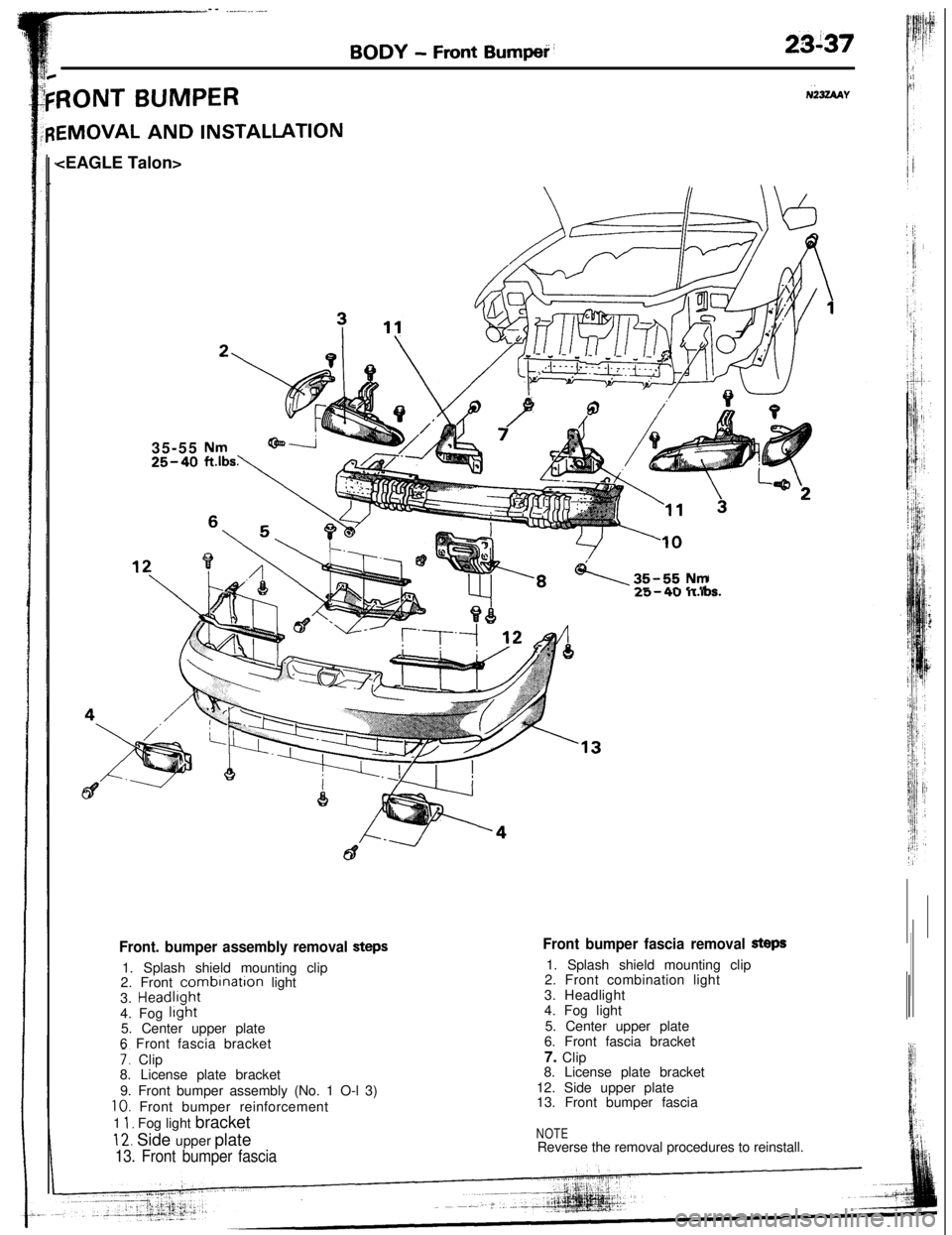
BODY - Front Bumped’23i37
RONT BUMPERNk4AY
EMOVAL AND INSTALLATION
35-55
25-40
\35-55Nma.-11 ._ II
Front bumper fascia removal Steps1. Splash shield mounting clip
2. Front combination light
3. Headlight
4. Fog light
5. Center upper plate
6. Front fascia bracket
7. Clip
8. License plate bracket
12. Side upper plate
13. Front bumper fasciaFront. bumper assembly removal steps1. Splash shield mounting clip
2. Front
combrnation light
3. Headlrght
4. Fog
light5. Center upper plate
6 Front fascia bracket
7. Clip
8. License plate bracket
9. Front bumper assembly (No. 1 O-l 3)
10. Front bumper reinforcement
1
1, Fog light bracket
12. Side upper plate
13. Front bumper fascia
NOTEReverse the removal procedures to reinstall.
Page 39 of 57
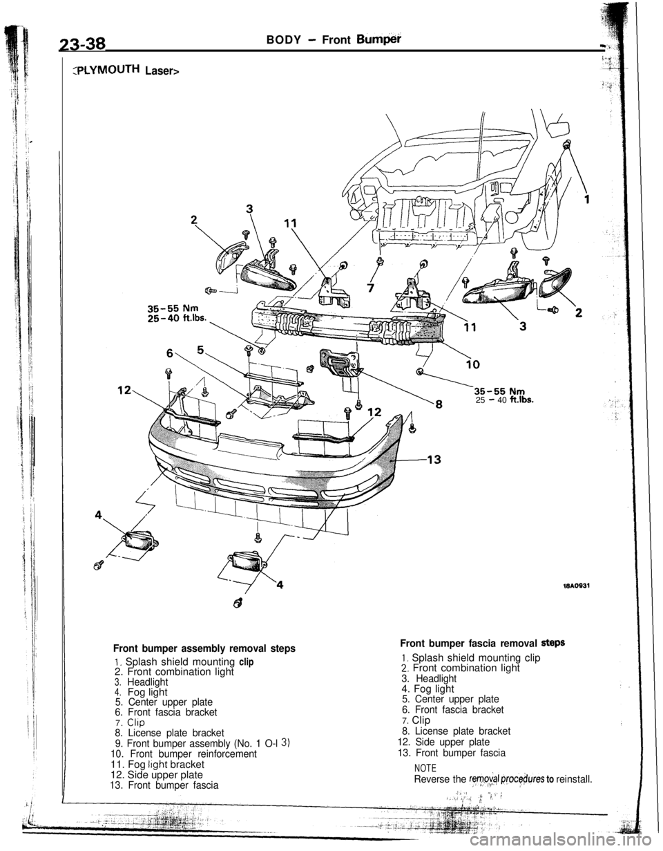
:PLYMOUTH Laser>25
- 40 ft.lbs.
23-38BODY - Front Bum$i
Front bumper assembly removal steps
1. Splash shield mounting clip
2. Front combination light
3.Headlight4.Fog light5. Center upper plate
6. Front fascia bracket7.
CllP8. License plate bracket
9. Front bumper assembly (No. 1 O-l
3)10. Front bumper reinforcement11. Fog light bracket
12. Side upper plate
13. Front bumper fascia
Front bumper fascia removal StePS
1, Splash shield mounting clip2. Front combination light
3. Headlight4. Fog light
5. Center upper plate
6. Front fascia bracket7. Clip
8. License plate bracket
12. Side upper plate
13. Front bumper fascia
NOTE
Reverse the ryv,o&+ ,rjrocebures to reinstall.,.,ir ,’.!,I,(1 ,(, /.; 1, !
Page 42 of 57
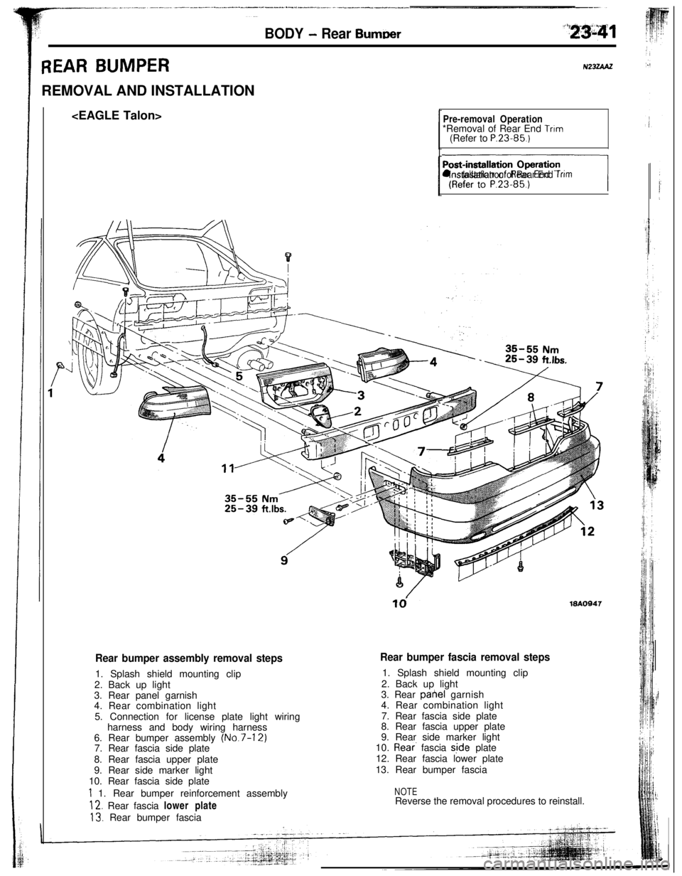
BODY - Rear Burn-r
REAR BUMPERREMOVAL AND INSTALLATION
Pre-removal Operation*Removal of Rear End Trim(Refer to P.23.85.)
nl lnstallatron of Rear End Trim
td19AO947
Rear bumper assembly removal steps1. Splash shield mounting clip
2. Back up light
3. Rear panel garnish
4. Rear combination light
5. Connection for license plate light wiring
harness and body wiring harness
6. Rear bumper assembly
(No.7-12)7. Rear fascia side plate
8. Rear fascia upper plate
9. Rear side marker light
10. Rear fascia side plate
1 1. Rear bumper reinforcement assembly
12. Rear fascia lower plate
13. Rear bumper fascia
Rear bumper fascia removal steps1. Splash shield mounting clip
2. Back up light
3. Rear pahel garnish
4. Rear combination light
7. Rear fascia side plate
8. Rear fascia upper plate
9. Rear side marker light
10.
Rear. fascia s,ide plate
12. Rear fascia lower plate
13. Rear bumper fascia
NOTEReverse the removal procedures to reinstall.
Page 43 of 57
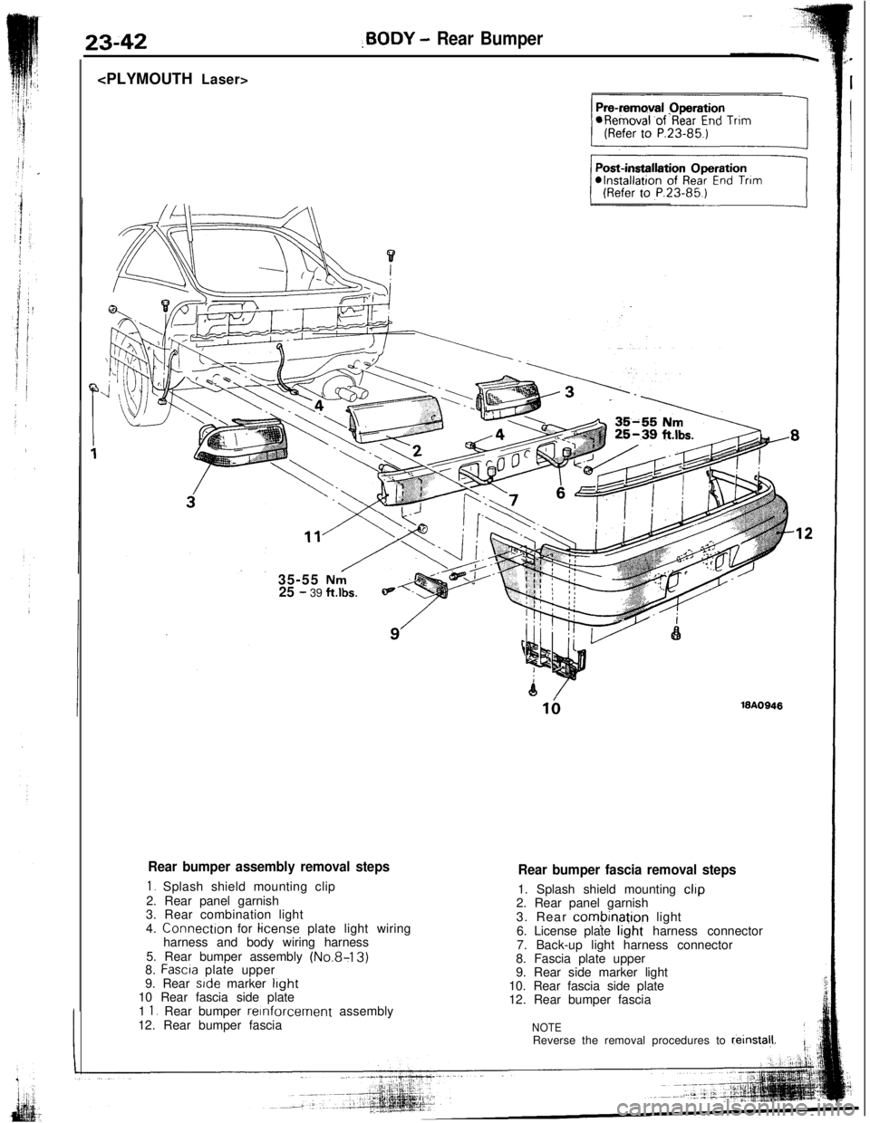
23-42,BODY - Rear Bumper
35-55
Nni25 - 39 ft.lbs.
Rear bumper assembly removal steps
1. Splash shield mounting clip
2. Rear panel garnish
3. Rear combination light
4. Connectron for
license plate light wiring
harness and body wiring harness
5. Rear bumper assembly
(No.8-13)8. Fascra plate upper
9. Rear side marker light10 Rear fascia side plate
1
1. Rear bumper reinforcement assembly
12. Rear bumper fascia
18A0948
Rear bumper fascia removal steps1. Splash shield mounting
clip2. Rear panel garnish
3. Rear
combinatjon light
6. License plate light harness connector
7. Back-up light harness connector
8. Fascia plate upper
9. Rear side marker light
10. Rear fascia side plate
12. Rear bumper fascia
NOTEReverse the removal procedures to reinstal,l.
Page 45 of 57
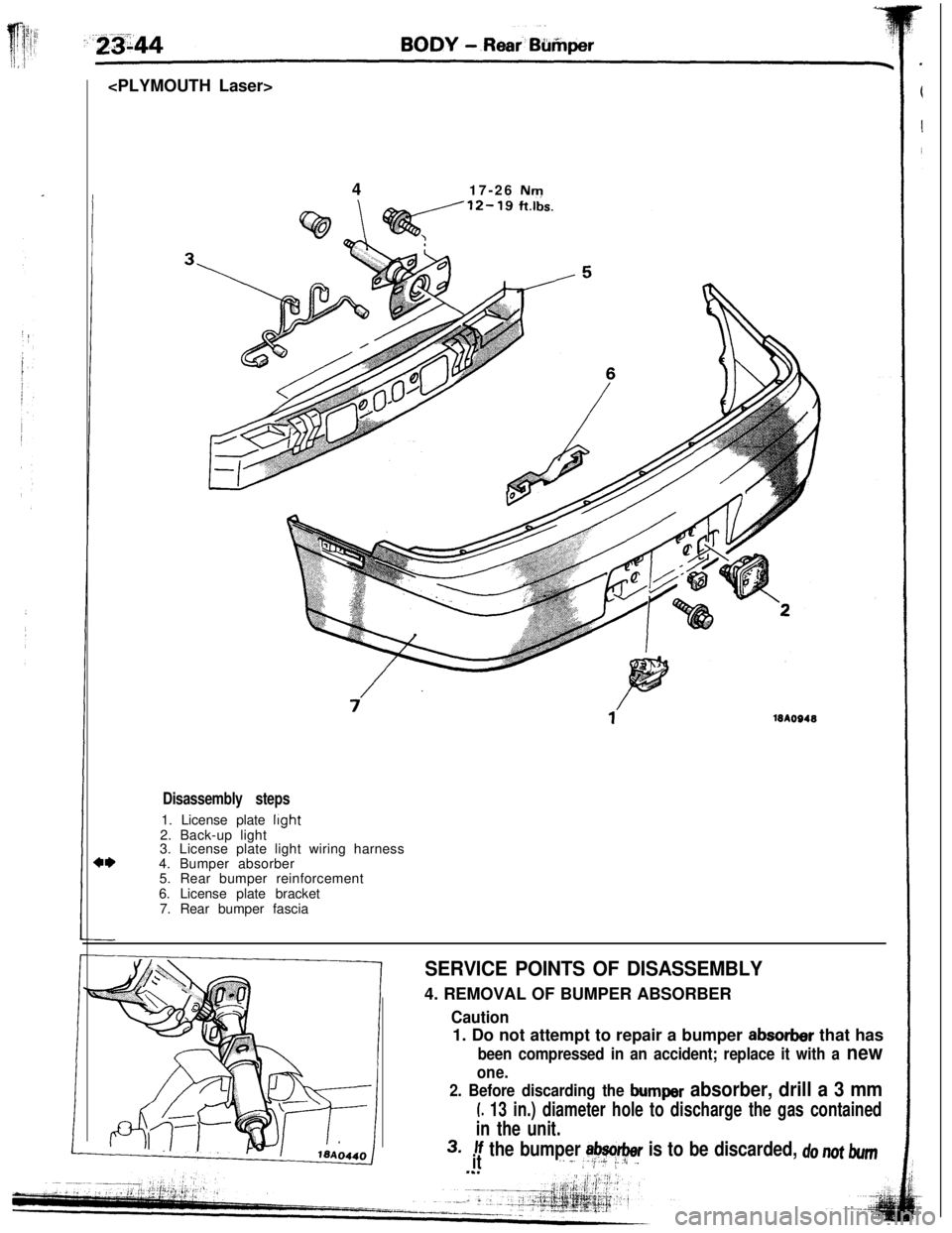
417-26 Nm
18AO948
Disassembly steps1. License plate
light2. Back-up light
3. License plate light wiring harness
4. Bumper absorber
5. Rear bumper reinforcement
6. License plate bracket
7. Rear bumper fascia
SERVICE POINTS OF DISASSEMBLY4. REMOVAL OF BUMPER ABSORBER
2. Before discarding the bumper absorber, drill a 3 mm
L 13 in.) diameter hole to discharge the gas contained
in the unit.
3.If the bumper absorber is to be discarded, do not bumit,. _..2;+ i_.I/~.L I
Caution1. Do not attempt to repair a bumper
absorber that has
been compressed in an accident; replace it with a new
one.
Page 46 of 57
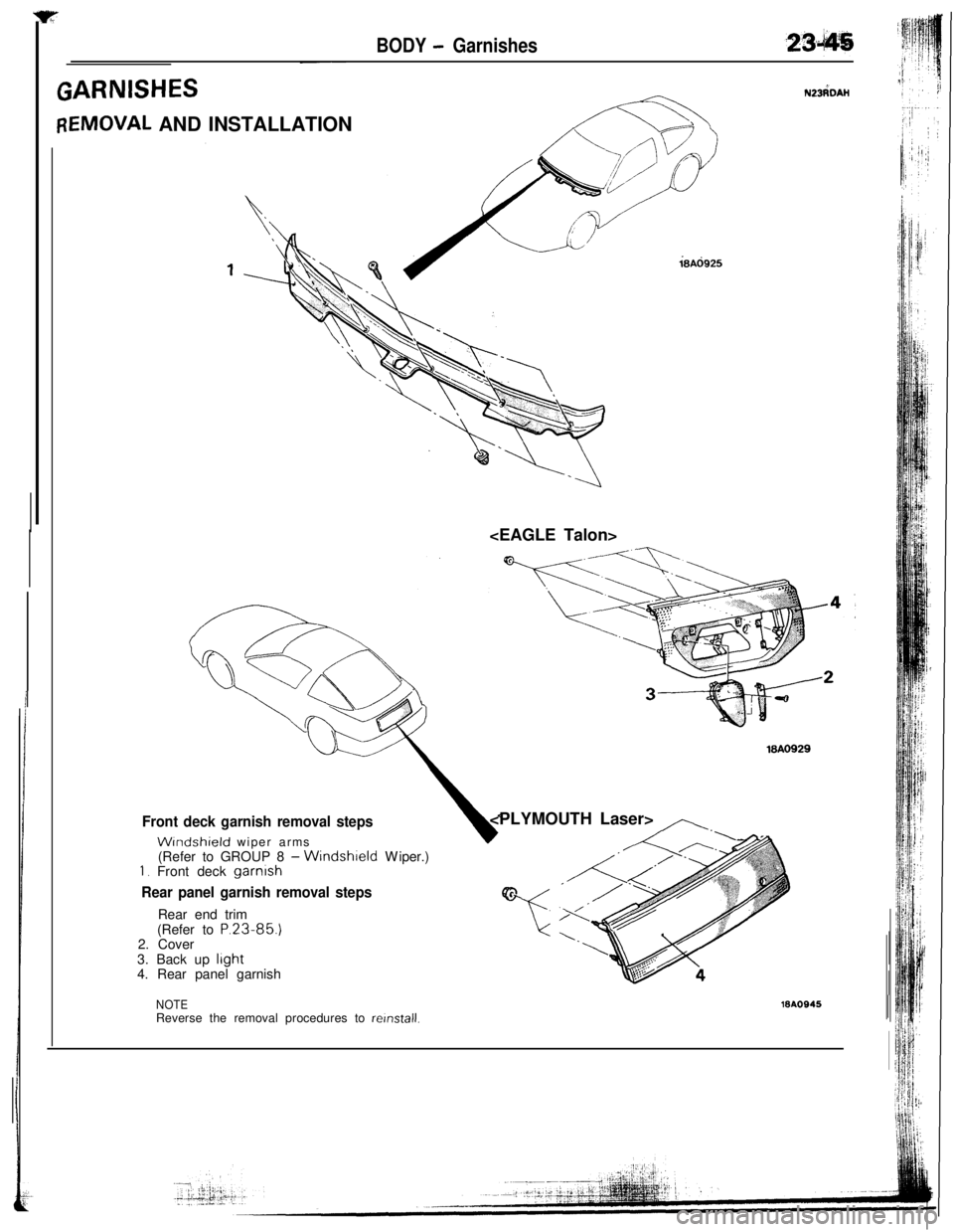
BODY - Garnishes-~
ZARNISHESN23dDAH
IEMOVAL AND INSTALLATION
18Ad925
18AO929
Front deck garnish removal steps
WIndshield wiper arms
(Refer to GROUP 8 -Windshield Wiper.)1. Front deck garnish
Rear panel garnish removal stepsRear end trim
(Refer to
P.23-85.)2. Cover
3. Back up
light4. Rear panel garnish
,,-..,.,-
E
“c
NOTEReverse the removal procedures to relnstall.16AOS45
Page 48 of 57
BODY - Moulding23-47
?8UO387
3.REMOVAL OF QUARTER WINDOW MOULDING LOWER/
4. QUARTER WINDOW MOULDING UPPER/B. QUARTER
WINDOW MOULDING FRONTRefer to P.23-59.
6. REMOVAL OF
LIFTGATE MOULDING LOWER17. LIFT-GATE MOULDING
UPPER/8. LIFTGATE MOULDING
SIDERefer to P.23-60.
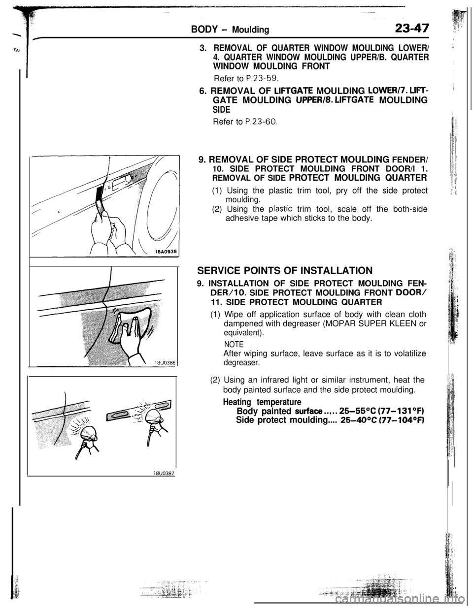
9. REMOVAL OF SIDE PROTECT MOULDING FENDER/
10. SIDE PROTECT MOULDING FRONT DOOR/l 1.
REMOVAL OF SIDE PROTECT MOULDING QUARTER(1) Using the plastic trim tool, pry off the side protect
moulding.(2) Using the
ptastic trim tool, scale off the both-side
adhesive tape which sticks to the body.
SERVICE POINTS OF INSTALLATION
9. INSTALLATION OF SIDE PROTECT MOULDING FEN-
DER/10. SIDE PROTECT MOULDING FRONT DOOR/11. SIDE PROTECT MOULDING QUARTER
(1) Wipe off application surface of body with clean cloth
dampened with degreaser (MOPAR SUPER KLEEN or
equivalent).
NOTEAfter wiping surface, leave surface as it is to volatilize
degreaser.(2) Using an infrared light or similar instrument, heat the
body painted surface and the side protect moulding.
Heating temperature
Body painted surface..,.. 25-55OC (77-131OF)
Side protect moulding....
25-40°C (77-104OF)
Page 50 of 57
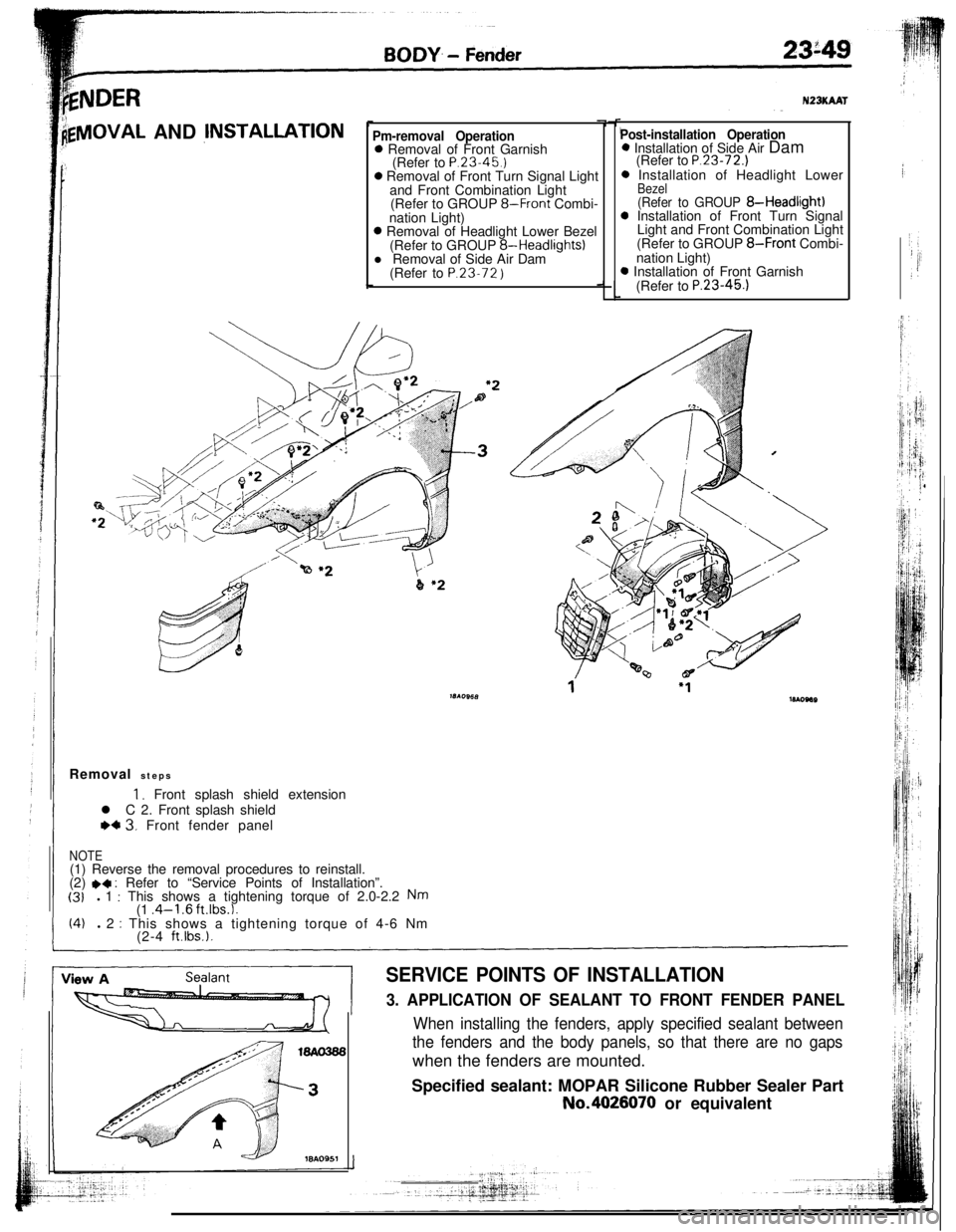
kNDER
lgVlOVAL AND jNSTALLATIONPm-removal Operation0 Removal of Front Garnish
(Refer to P.23.45.)0 Removal of Front Turn Signal Light
and Front Combination Light
(Refer to GROUP
8-Front Combi-
nation Light)0 Removal of Headlight Lower Bezel
(Refer to GROUP 8-Headlights)
l Removal of Side Air Dam
(Refer to P.23.72
)
N23KAAT
Post-installation Operation0 Installation of Side Air Dam
(Refer to
P.23-72.)0 Installation of Headlight Lower
Bezel(Refer to GROUP 8-Headlight)0 Installation of Front Turn Signal
Light and Front Combination Light
(Refer to GROUP
8-Front Combi-
nation Light)0 Installation of Front Garnish
(Refer to
P.23-45.1Removal steps
1, Front splash shield extension
l C 2. Front splash shield
WC 3. Front fender panel
NOTE(1) Reverse the removal procedures to reinstall.
(2)
.4 : Refer to “Service Points of Installation”.(31l 1 : This shows a tightening torque of 2.0-2.2 Nm(1 .4-l .6 ft.lbs.1.(4)l 2 : This shows a tightening torque of 4-6 Nm
(2-4 ft.lbs.).
SERVICE POINTS OF INSTALLATION
3. APPLICATION OF SEALANT TO FRONT FENDER PANEL
When installing the fenders, apply specified sealant between
the fenders and the body panels, so that there are no gapswhen the fenders are mounted.
Specified sealant: MOPAR Silicone Rubber Sealer PartNo.4026070 or equivalent
Page 52 of 57
*,i
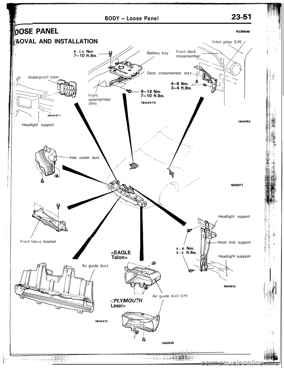
bSE PANEL
BODY - Loose Panel23-51
N23sAAK/&OVAL AND INSTALLATION
.-9-14
Nm.7-10 ft.k
Front pillar ILH) /Headlight support
Inter cooler duct
Front/fascia bracket
/crossmember
Deck crossmember sta
lSA0463
18AO971Headlight support
Nm3-4 ft.lbs.Hood lock support
WA0970
ISA0472
LT IVIUUIn
Laser>I
18AO939