wiring MITSUBISHI ECLIPSE 1993 Workshop Manual
[x] Cancel search | Manufacturer: MITSUBISHI, Model Year: 1993, Model line: ECLIPSE, Model: MITSUBISHI ECLIPSE 1993Pages: 57, PDF Size: 4.18 MB
Page 36 of 57

BODY - Liftgate23-35
FTGATEN230AAT
EMOVAL AND INSTALLATION
11-16 Nm
8- 12 ft.lbs.\9-14 Nm
7- 10 ftlbs.
1. Bumper
2. Llftgate damper (upper)
3. Liftgate outer weatherstrip
4. Liftgate damper (lower)
5. Liftgate opening weatherstrip
Liftgate hinge removal stepsHeadlining (Refer to
P.23-89.)6. Connection for rear washer tube
Center pillar trim (drtver’s side)
Quarter trim (driver’s side)
1(Refer toP.23-85.)7. Connection for liftgate wiring harness
8. Liftgate
9. Liftgate hinge
Liftgate removal steps6. Connection for rear washer tube
Center pillar trim (driver’s side)(Refer to
Quarter trim (driver’s side)
1P.23-85.)7. Connection for
liftgate wiring harness
8. Liftgate
Liftgate lock release cable removal stepsRear seat (Refer to
P.23-93.)Scuff plate (driver’s side)
Quarter trim (driver’s side)
(Refer to
Rear end trim
’ P.23-85.)Rear side trim
l
10. Liftgate latch5-8 ftlbs.
4/
1118AO973
Liftgate lock release handle removal stepsScuff plate (driver’s side)
(Refer to
P.23-85.)13 Release handle cover
l * 14.
Liftgate lock release handle
Liftgate latch removal stepsRear end trim (Refer to
P.23-85.)l *
10. Liftgate latch
Liftgate lock cylinder removal stepsRear end trim (Refer to P-23-85.)
1 1 Retainer
4*12.
Liftgate lock cylinder
Liftgate striker removal steps
Liftgate trim (Refer to P.23-86.)16
Liftgate striker
Liftgate stopper removal stepsRear side trim (Refer
td P.23-85.)
17. Liftgate stopper
Page 42 of 57

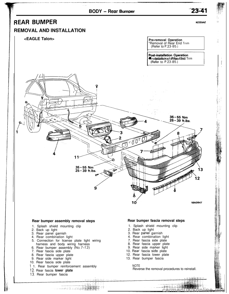
BODY - Rear Burn-r
REAR BUMPERREMOVAL AND INSTALLATION
Pre-removal Operation*Removal of Rear End Trim(Refer to P.23.85.)
nl lnstallatron of Rear End Trim
td19AO947
Rear bumper assembly removal steps1. Splash shield mounting clip
2. Back up light
3. Rear panel garnish
4. Rear combination light
5. Connection for license plate light wiring
harness and body wiring harness
6. Rear bumper assembly
(No.7-12)7. Rear fascia side plate
8. Rear fascia upper plate
9. Rear side marker light
10. Rear fascia side plate
1 1. Rear bumper reinforcement assembly
12. Rear fascia lower plate
13. Rear bumper fascia
Rear bumper fascia removal steps1. Splash shield mounting clip
2. Back up light
3. Rear pahel garnish
4. Rear combination light
7. Rear fascia side plate
8. Rear fascia upper plate
9. Rear side marker light
10.
Rear. fascia s,ide plate
12. Rear fascia lower plate
13. Rear bumper fascia
NOTEReverse the removal procedures to reinstall.
Page 43 of 57

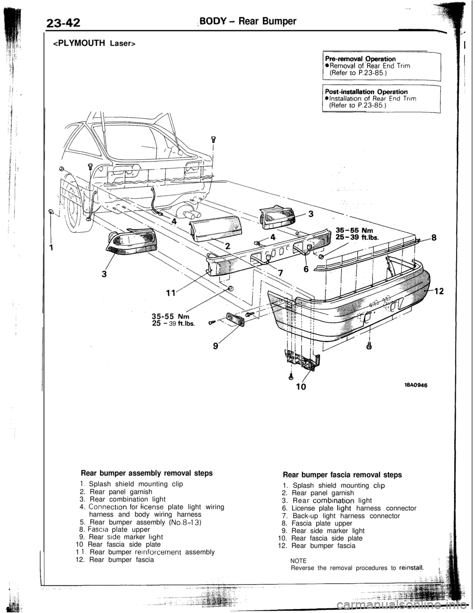
23-42,BODY - Rear Bumper
35-55
Nni25 - 39 ft.lbs.
Rear bumper assembly removal steps
1. Splash shield mounting clip
2. Rear panel garnish
3. Rear combination light
4. Connectron for
license plate light wiring
harness and body wiring harness
5. Rear bumper assembly
(No.8-13)8. Fascra plate upper
9. Rear side marker light10 Rear fascia side plate
1
1. Rear bumper reinforcement assembly
12. Rear bumper fascia
18A0948
Rear bumper fascia removal steps1. Splash shield mounting
clip2. Rear panel garnish
3. Rear
combinatjon light
6. License plate light harness connector
7. Back-up light harness connector
8. Fascia plate upper
9. Rear side marker light
10. Rear fascia side plate
12. Rear bumper fascia
NOTEReverse the removal procedures to reinstal,l.
Page 45 of 57

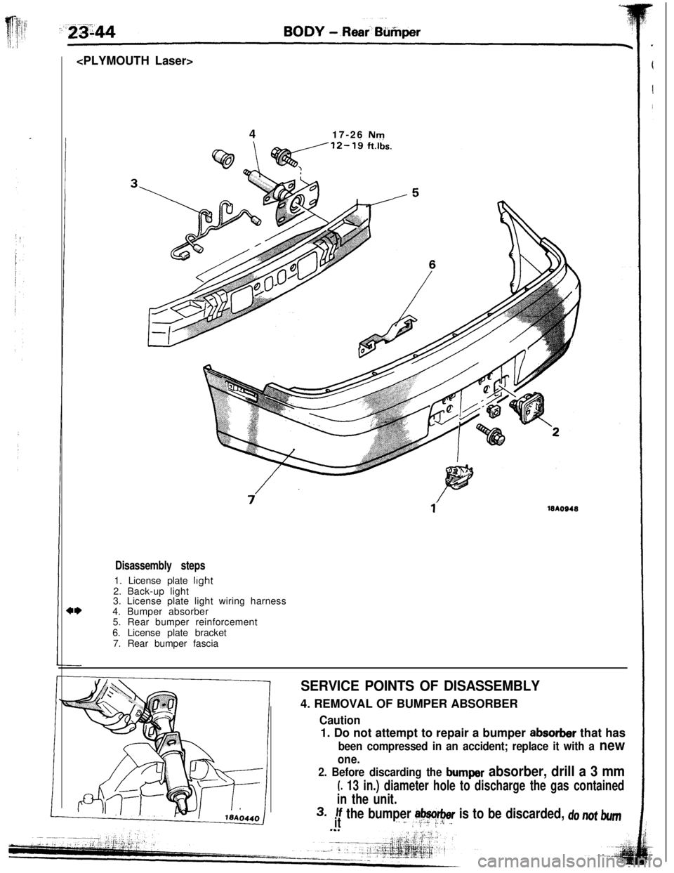
417-26 Nm
18AO948
Disassembly steps1. License plate
light2. Back-up light
3. License plate light wiring harness
4. Bumper absorber
5. Rear bumper reinforcement
6. License plate bracket
7. Rear bumper fascia
SERVICE POINTS OF DISASSEMBLY4. REMOVAL OF BUMPER ABSORBER
2. Before discarding the bumper absorber, drill a 3 mm
L 13 in.) diameter hole to discharge the gas contained
in the unit.
3.If the bumper absorber is to be discarded, do not bumit,. _..2;+ i_.I/~.L I
Caution1. Do not attempt to repair a bumper
absorber that has
been compressed in an accident; replace it with a new
one.