height MITSUBISHI ECLIPSE CROSS 2018 (in English) User Guide
[x] Cancel search | Manufacturer: MITSUBISHI, Model Year: 2018, Model line: ECLIPSE CROSS, Model: MITSUBISHI ECLIPSE CROSS 2018Pages: 417, PDF Size: 74.06 MB
Page 173 of 417
Adaptive Cruise Control System (ACC) (if so equipped) 5-94 Features and controls
5
N00581500043
There are two ways to increase the set speed. The set speed will increase by 1 mph (1.6 km/h) every time you push up the“RES +” switch while the ACC is activated. If you hold the switch pushed up, the set speed increases in 5 mph (8 km/h) incre-ments.
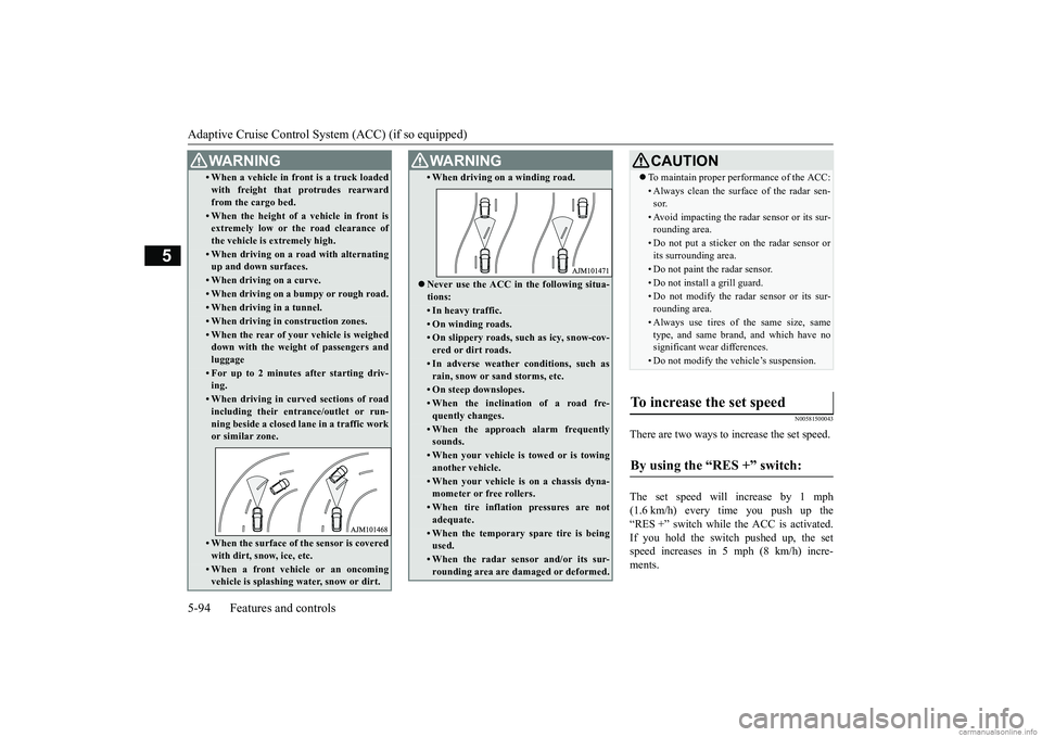
• When a vehicle in front is a truck loaded with freight that protrudes rearward from the cargo bed.• When the height of a vehicle in front isextremely low or the road clearance of the vehicle is extremely high.• When driving on a road with alternatingup and down surfaces.• When driving on a curve.• When driving on a bumpy or rough road.• When driving in a tunnel.• When driving in construction zones.• When the rear of your vehicle is weighed down with the weight of passengers and luggage• For up to 2 minutes after starting driv-ing.• When driving in curved sections of roadincluding their entrance/outlet or run- ning beside a closed lane in a traffic workor similar zone.• When the surface of the sensor is coveredwith dirt, snow, ice, etc.• When a front vehicle or an oncomingvehicle is splashing water, snow or dirt. WA R N I N G
• When driving on a winding road. Never use the ACC in the following situa- tions:• In heavy traffic.• On winding roads.• On slippery roads, such as icy, snow-cov- ered or dirt roads.• In adverse weather conditions, such asrain, snow or sand storms, etc.• On steep downslopes.• When the inclination of a road fre- quently changes.• When the approach alarm frequentlysounds.• When your vehicle is towed or is towinganother vehicle.• When your vehicle is on a chassis dyna-mometer or free rollers.• When tire inflation pressures are notadequate.• When the temporary spare tire is beingused.• When the radar sensor and/or its sur-rounding area are damaged or deformed.WA R N I N G
CAUTION To maintain proper performance of the ACC:• Always clean the surface of the radar sen- sor.• Avoid impacting the radar sensor or its sur-rounding area.• Do not put a sticker on the radar sensor orits surrounding area.• Do not paint the radar sensor.• Do not install a grill guard.• Do not modify the radar sensor or its sur- rounding area.• Always use tires of the same size, sametype, and same brand, and which have nosignificant wear differences.• Do not modify the vehicle’s suspension.
To increase the set speed
By using the “RES +” switch:
BK0252700US.bo
ok 94 ページ 2017年10月4日 水曜日 午後4時54分
Page 181 of 417
Forward Collision Mitigation sy
stem (FCM) (if so equipped)
5-102 Features and controls
5
• When a vehicle ahead is not completely in your path.• When your vehicle changed lanes, and your vehicle approached immediatelybehind the vehicle ahead.• When a vehicle ahead is towing a trailer.• When a vehicle ahead is a truck loadedwith freight that protrudes rearwardfrom the cargo bed.• When the height of a vehicle ahead isextremely low or its road clearance is extremely high.• When a vehicle ahead is extremely dirty.• When a vehicle ahead is covered with snow.• When a vehicle ahead has a large glasssurface.• When a vehicle ahead does not havereflectors (light reflector) or the position of the reflector is low.• When a vehicle ahead is a car carrier ora similar shaped vehicle.• When accelerating and deceleratingquickly.• When driving on a slippery road coveredby rain water, snow, ice, etc.• When driving on a road with alternating up and down steep slopes.• When driving on a curve.• When driving on a bumpy or rough road.• When driving in dark areas, such as in atunnel or at night.WA R N I N G
• When the system recognizes driver’s steering, accelerating, braking or gear shifting actions as evasive actions to avoid collision.• When the rear of your vehicle is weigheddown with the weight of passengers and luggage.• Up to several seconds after starting driv-ing.• In adverse weather conditions, such asrain, snow, fog or sand-storm.• When the windshield of the sensor por-tion is covered with dirt, water droplets,snow and ice, etc.• When a vehicle ahead or an oncomingvehicle is splashing water, snow or dirt. • When using a windshield washer.• If windshield wipers are not MitsubishiMotors Genuine parts or equivalent. • When the sensor becomes extremely hotor cold.• If the battery becomes weak or runsdown.• When the sensor is affected by stronglight, such as direct sunlight or the head-lights of an oncoming vehicle.
The FCM may not detect a pedestrian in certain situations. Some of these include:• If the pedestrian is shorter than approxi-mately 3.2 feet (1 m) or taller than approximately 6.5 feet (2 m).WA R N I N G
• If the pedestrian is wearing loose-fitting clothes.• If part of a pedestrian’s body is hidden, such as when holdin
g an umbrella, large
bag, etc.• If a pedestrian bends forward, sits or lieson the road.• When a pedestrian is pushing/pullingsomething, such as a stroller, bicycle or wheelchair.• When pedestrians gather in a group.• When a pedestrian clothing appears to be nearly the same color or brightness as its surroundings.• When a pedestrian is very close to anobject, such as a vehicle.• When a pedestrian is in a dark area, suchas at night or in a tunnel.• When a pedestrian is walking fast orrunning.• When a pedestrian suddenly rushes infront of the vehicle.• When the position of a pedestrian is closeto the edge of the vehicle.
When the system recognizes driver’s steering or accelerating actions as evasive actions to avoid a collision, FCM control and alarm functions may be canceled. In certain situations, though there is little or no risk of a collision, the FCM may activate. Examples include: • When overtaking a vehicle.WA R N I N G
BK0252700US.book
102 ページ 2017年10月4日 水曜日 午後4時54分
Page 188 of 417
Blind Spot Warning (BSW) (with Lane
Change Assist) (if so equipped) Features and controls 5-109
5
N00593500053
When the ignition switch is turned to the “ON” position or the operation mode is put in
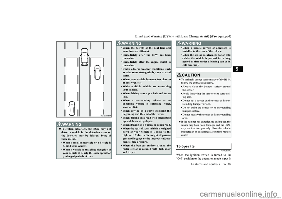
WA R N I N G In certain situations, the BSW may not detect a vehicle in the detection areas orthe detection may be delayed. Some of these include;• When a small motorcycle or a bicycle isbehind your vehicle.• When a vehicle is traveling alongside ofyour vehicle at nearly the same speed for prolonged periods of time.
• When the heights of the next lane and your lane are different.• Immediately after the BSW has been turned on.• Immediately after the engine switch isturned on.• Under adverse weather conditions, suchas rain, snow, strong winds, snow or sandstorm.• When your vehicle becomes too close toanother vehicle.• While multiple vehicle are overtakingyour vehicle.• When driving near a pot hole and tram-line.• When a surrounding vehicle or anoncoming vehicle is splashing water, snow or dirt.• When driving on a curve including thebeginning and the end of the curve.• When driving on a road with alternatingup and down steep slopes.• When driving on a bumpy or rough road.• When the rear of your vehicle is weighed down or your vehicle is leaning to the right or left due to the weight of passen- gers and luggage or the improper adjust- ment of tire pressure. • When the bumper surface around theradar sensor is covered with dirt, snow and ice, etc.WA R N I N G
• When a bicycle carrier or accessory is installed to the rear of the vehicle.• When the sensor is extremely hot or cold (while the vehicle is parked for a longperiod of time under a blazing sun or in cold weather).CAUTION To maintain proper performance of the BSW, follow the instructions below.• Always clean the bumper surface aroundthe sensor.• Avoid impacting the sensor or its surround-ing area.• Do not put a sticker on the sensor or its sur-rounding bumper surface.• Do not paint the sensor or its surroundingbumper surface.• Do not modify the sensor or its surroundingarea.
If the bumper has experienced an impact, the sensor may have been damaged and the BSWmay not function properly. Have the vehicle inspected at an authorized Mitsubishi Motors dealer.
To operate
WA R N I N G
BK0252700US.book
109 ページ 2017年10月4日 水曜日 午後4時54分
Page 202 of 417
Parking sensors (Front/Rear) (if so equipped)
Features and controls 5-123
5
N00589800042
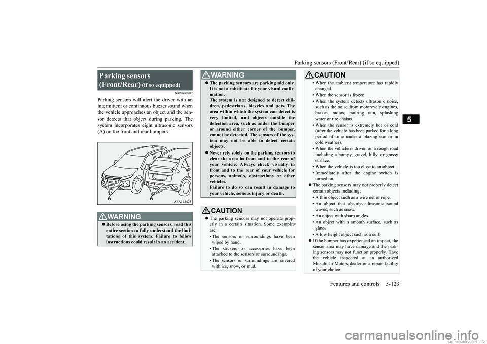
Parking sensors will alert the driver with an intermittent or continuous buzzer sound whenthe vehicle approaches an object and the sen- sor detects that object during parking. The system incorporates eight ultrasonic sensors(A) on the front and rear bumpers.Parking sensors (Front/Rear)
(if so equipped)
WA R N I N G Before using the parking sensors, read this entire section to fully understand the limi-tations of this system. Failure to follow instructions could result in an accident.
The parking sensors are parking aid only. It is not a substitute for your visual confir- mation. The system is not designed to detect chil- dren, pedestrians, bicycles and pets. Thearea within which the system can detect is very limited, and ob
jects outside the
detection area, such as under the bumperor around either corner of the bumper, cannot be detected. The sensors of the sys- tem may not be able to detect certainobjects. Never rely solely on the parking sensors to clear the area in front and to the rear of your vehicle. Always check visually in front and to the rear of your vehicle forpersons, animals, obstructions or other vehicles. Failure to do so can result in damage toyour vehicle, serious injury or death.CAUTION The parking sensors may not operate prop- erly in a certain situation. Some examples are:• The sensors or surroundings have beenwiped by hand.• The stickers or accessories have beenattached to the sensors or surroundings.• The sensors or surroundings are coveredwith ice, snow, or mud.WA R N I N G
• When the ambient temperature has rapidly changed.• When the sensor is frozen.• When the system detects ultrasonic noise,such as the noise from motorcycle engines, brakes, radios, pouring rain, splashingwater or tire chains.• When the sensor is extremely hot or cold(after the vehicle has been parked for a long period of time under a blazing sun or in cold weather).• When the vehicle is driven on a rough roadincluding a bumpy, gravel, hilly, or grassysurface.• When the vehicle is too close to an object.• Immediately after the engine switch isturned on.
The parking sensors may not properly detect certain objects including;• A thin object such as a wire net or rope.• An object that absorbs ultrasonic sound waves, such as snow.• An object with sharp angles.• An object with a smooth surface, such as glass.• A low height object such as a curb. If the bumper has experienced an impact, the sensor area may have damage and the park- ing sensors may not function properly. Have the vehicle inspected at an authorizedMitsubishi Motors dealer or a repair facility of your choice.CAUTION
BK0252700US.book
123 ページ 2017年10月4日 水曜日 午後4時54分
Page 204 of 417
Parking sensors (Front/Rear) (if so equipped)
Features and controls 5-125
5
To switch to the towing hitch mode and return to the normal mode, refer to “Changing the detection mode” on page 5-126.
N00590000044
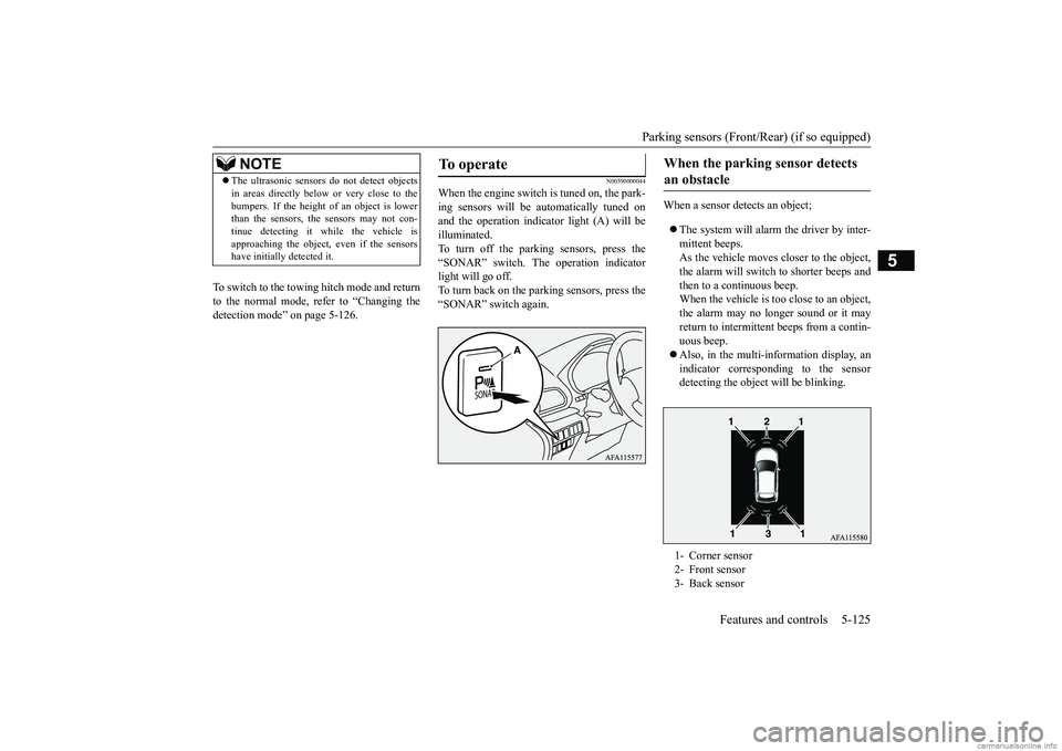
When the engine switch is tuned on, the park- ing sensors will be automatically tuned onand the operation indi
cator light (A) will be
illuminated. To turn off the parking sensors, press the“SONAR” switch. The operation indicator light will go off. To turn back on the parking sensors, press the“SONAR” switch again.
When a sensor detects an object; The system will alarm the driver by inter- mittent beeps. As the vehicle moves closer to the object, the alarm will switch to shorter beeps andthen to a continuous beep. When the vehicle is too close to an object, the alarm may no longer sound or it mayreturn to intermittent beeps from a contin-uous beep. Also, in the multi-information display, an indicator corresponding to the sensordetecting the object will be blinking.
NOTE
The ultrasonic sensors do not detect objects in areas directly below or very close to the bumpers. If the height of an object is lower than the sensors, the sensors may not con- tinue detecting it while the vehicle isapproaching the object,
even if the sensors
have initially detected it.
To operate
When the parking sensor detects an obstacle
1- Corner sensor 2- Front sensor 3- Back sensor
BK0252700US.book
125 ページ 2017年10月4日 水曜日 午後4時54分
Page 217 of 417
Multi Around Monitor (if so equipped) 5-138 Features and controls
5
N00588000034
An overhead view in which the vehicle is looked down is displayed so that you can eas-ily identify the location of your vehicle and the course to enter the parking space.
N00594200028
It is possible to change the vehicle icon colorin the bird’s eye-view. 1. Stop the vehicle in a safe place.
Bird’s eye-view mode
CAUTION The bird’s eye-view is a composite image from images captured by the “Front-view camera”, “Side-view cameras (right and left)” and “Rear-view camera”. As a result, objects may appear to be farther away thanthey actually are. Also, an object may appear to be in a direction a
nd/or location different
from actual. In addition, blind spots exist inproximity of the vehicle. Even if the screen indicates that there is a space between your vehicle and an object,there may actually be less or no space. Always check visually behind and all around your vehicle. The view at a section near each corner on the Bird's eye-view is combined from the edgeof the view captured by each camera. As result, an object indicated in the section may be unclear, and it may disappear/reappear onthe screen.NOTE
In the Bird’s eye-view mode, since the views captured by the four cameras, “Front-view camera”, “Side-view cameras (right and left)” and “Rear-view camera” are processedbased on a level flat road surface, an image may be displayed as follows: • An object appears to have fallen down and looks longer or larger.
• An object having a height from the roadsurface may seem to appear from the joint of the view composition processing regions.
The brightness of the views from each cam- era may vary depending on the illuminance conditions. An object above the camera is not displayed. The object displayed in the Front-view mode or the Rear-view mode may not be displayed in the Bird’s eye-view mode. The view in the Bird’s eye-view mode may be displaced from its
true position when the
mounting location and angle of each camera are changed. The lines on the road may appear to be dis- placed or bent at the joint of the views.
To change the vehicle icon color in the bird’s eye-view
CAUTION For reasons of safety, do not operate the switch while driving.NOTE
BK0252700US.book
138 ページ 2017年10月4日 水曜日 午後4時54分
Page 315 of 417
Trailer towing 6-12 Driving safety
6
The tongue weight of any trailer is important because it affects the vehicle capacity weight. The vehicle capacity weight includes anycargo you may carry, and the people who will be riding in the vehicle. If you will tow a trailer, you must include the tongue weight ofthe trailer in your calculation of the vehicle capacity weight. For more information regarding vehicle capacity weight, refer to“Tire and loading information placard” onpage 6-7. Do not exceed the maximum tongue weight for your vehicle. After you’ve loaded your trailer, weigh the trailer and then the tongue, separately, to see if the weights are proper.Keep the trailer tongue load at 10 % of the loaded trailer weight for dead weight hitches. Tongue loads can be adjusted by proper dis-
tribution of the load in the trailer. This can be checked by separately weighing the loaded trailer and then the tongue. The GAWRs are printed on the certification label which is riveted on the door sill on the driver’s side.Refer to “Vehicle labeling” on page 11-2. Choose a proper hitch and ball, and make sure it is installed at a height that is compati-ble with the trailer. Use a good equalizing hitch which uniformly distributes the trailer tongue load throughoutthe frame.
A safety chain must always be used between the towing vehicle and the trailer. Leave suf- ficient slack in the chain for turns. The chain should cross under the trailer tongue to pre-vent the tongue from dropping to the ground in case it becomes damaged or separated. For correct safety chain procedures, consultyour authorized Mitsubishi Motors dealer.
Tongue weight Vehicle condi-
tion
Maximum tongue weight
1 or 2 persons
seated
With brake 200 lb (91 kg) Without brake 125 lb
(57 kg)
3–5 persons
seated
With brake 150 lb (68 kg) Without brake 125 lb
(57 kg)
Gross axle weight rating (GAWR) Trailer hitches
WA R N I N G If you make any holes in the body of your vehicle for installing a trailer hitch, be sure to seal the holes later when you remove the hitch. If you don’t seal them, deadly carbon monoxide (CO) from your exhaust can enter your
vehicle. Refer to
“Exhaust system” on page 9-22.
NOTE
Mitsubishi Motors recommends that sway control be used whenever you are towing, to improve towing stability. For further information, please contact your authorized Mitsubishi Motors dealer.
Safety chains
CAUTION Never tow a trailer without using a safety chain securely attached to both the trailer and the vehicle. If the coupling unit or hitch ball experiences a problem, the trailer may separate from your vehicle.
BK0252700US.bo
ok 12 ページ 2017年10月4日 水曜日 午後4時54分
Page 370 of 417
Tires
Vehicle care and maintenance 9-13
9
Sidewall: portion of a tire between the tread and bead. Section width: the li
near distance between
the exteriors of the sidewalls of aninflated tire, excluding elevations due to labeling, decoration, or protective bands. Bead: the part of the tire that is made of steel wires, wrapped or reinforced by ply cords and that is shaped to fit the rim. Ply: a layer of rubber-coated parallel cords. Cord: the strands forming the plies in the tire. Rim: a metal support for a tire or a tire and tube assembly upon which the tire beads are seated. Rim diameter: nominal diameter of the bead seat. Groove: the space between two adjacent tread ribs.
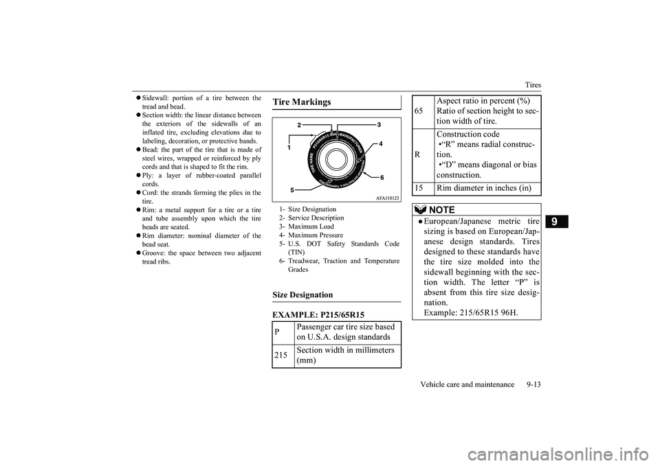
EXAMPLE: P215/65R15Tire Markings 1- Size Designation 2- Service Description 3- Maximum Load4- Maximum Pressure 5- U.S. DOT Safety Standards Code
(TIN)
6- Treadwear, Traction and Temperature
Grades
Size Designation P
Passenger car tire size based on U.S.A. design standards
215
Section width in millimeters (mm)
65
Aspect ratio in percent (%) Ratio of section height to sec- tion width of tire.
R
Construction code •“R” means radial construc- tion. •“D” means diagonal or bias construction.
15 Rim diameter in inches (in)
NOTE
European/Japanese metric tire sizing is based on European/Jap-anese design standards. Tires designed to these standards have the tire size molded into thesidewall beginning with the sec- tion width. The letter “P” is absent from this tire size desig-nation. Example: 215/65R15 96H.
BK0252700US.bo
ok 13 ページ 2017年10月4日 水曜日 午後4時54分
Page 407 of 417
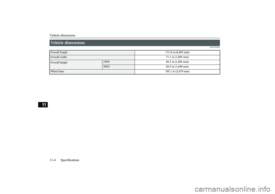
Vehicle dimensions 11-4 Specifications
11
N01147501681
Vehicle dimensions Overall length
173.4 in (4,405 mm)
Overall width
71.1 in (1,805 mm)
Overall height
2WD 66.3 in (1,685 mm)4WD 66.5 in (1,690 mm)
Wheel base
105.1 in (2,670 mm)
BK0252700US.bo
ok 4 ページ 2017年10月4日 水曜日 午後4時54分
Page 415 of 417
Alphabetical index 12-4
12
Overheating
......................
...................
8-4
P
Parking
.........................
.......................
6-6
Parking brake
................
.................
5-46
Parking brake lever stroke
...................
9-19
Parking lights
Bulb location and capacity
...............
9-28
Replacement
.................
.................
9-30
Parking sensors
.................
...............
5-123
Polishing
.......................
.....................
9-38
Power brakes
.....................
.................
5-74
Power outlet
..................
...................
5-208
Power panoramic sunroof
....................
5-43
Power windows
.................
.................
5-40
Puncture (Tire changing)
.......................
8-6
R
Radiator cap
......................
...................
9-8
Reading lights
Bulb location and capacity
...............
9-29
Rear axle oil
...............
.................
9-9
, 11-7
Rear combination lights
Bulb location and capacity
...............
9-28
Replacement
.................
.................
9-32
Rear Cross Traffic Alert
....................
5-112
Rear seat adjustment
.............................
4-6
Rear side-marker lights
Bulb location and capacity
...............
9-28
Rear turn signal light
Bulb location and capacity
...............
9-28
Replacement
...................
................
9-32
Rear-view camera
.............................
5-127
Rearview mirror
Inside rearview mirror
.....................
5-51
Outside rearview mirrors
.................
5-53
Replacement of light bulbs
...................
9-27
Replacing tires and wheels
...................
9-16
Reporting Safety Defects
.....................
10-2
S
Safe driving techniques
.........................
6-4
S-AWC (Super-All Wheel Control)
......
5-67
Seat belt
......................
.......................
4-13
Adjustable seat belt shoulder anchor
.4-19
Child restraint systems
.....................
4-22
Front passenger seat belt warning light
.....
4-19 Maintenance and inspection
.............
4-30
Seat belt extender
............................
4-20
Seat belt force limitter
.....................
4-22
Seat belt pre-tensioners
....................
4-21
Seat belt use during pregnancy
.........
4-21
Seats
...........................
........................
4-2
Arm rest
..................
..................
4-6
, 4-8
Front seats
...................
....................
4-3
Head restraints
.................
................
4-9
Making a cargo area
........................
4-12
Rear seats
.....................
...................
4-6
Seats and restraint systems
................
4-3
Service brake
.....................
.................
5-73
Service precautions
...............
................
9-2
Side turn signal light
Bulb location and capacity
...............
9-28
Snow tires
.....................
.....................
9-18
Spark plugs
...................
.....................
9-20
Starting the engine
.....................
5-24
, 5-58
Steering
Steering wheel height and reach adjustment 5-50
Stop lights
Bulb location and capacity
...............
9-28
Storage spaces
...................
...............
5-217
Sun visors
.....................
...................
5-207
Super-all wheel control (S-AWC)
S-AWC drive mode display
.............
5-69
S-AWC drive mode-selector
............
5-68
S-AWC operation display
................
5-69
Supplemental Restraint System
............
4-30
How the Supplemental Restraint System works
.....................
.....................
4-33
Maintenance service
.......................
4-45
BK0252700US.bo
ok 4 ページ 2017年10月4日 水曜日 午後4時54分