tire type MITSUBISHI ECLIPSE CROSS 2018 Owner's Manual (in English)
[x] Cancel search | Manufacturer: MITSUBISHI, Model Year: 2018, Model line: ECLIPSE CROSS, Model: MITSUBISHI ECLIPSE CROSS 2018Pages: 417, PDF Size: 74.06 MB
Page 148 of 417
S-AWC (Super-All Wheel Control) (if so equipped)
Features and controls 5-69
5
N00583100043
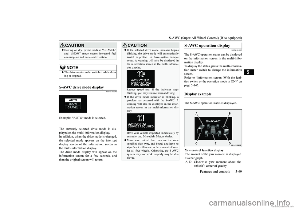
The currently selected drive mode is dis- played on the multi-information display. In addition, when the drive mode is changed, the selected mode appears on the interruptdisplay screen of the information screen in the multi-information display. The drive mode display will appear on theinformation screen for a few seconds, and then the original screen will return.
N00542501087
The S-AWC operation status can be displayed on the information screen in the multi-infor-mation display. To display the status, press the multi-informa- tion meter switch to change the informationscreen. Refer to “Information screen (With the igni- tion switch or the operation mode in ON)” onpage 5-145. The S-AWC operation status is displayed.
Driving on dry, paved roads in “GRAVEL” and “SNOW” mode causes increased fuel consumption and noise and vibration.NOTE
The drive mode can be switched while driv- ing or stopped.
S-AWC drive mode display
Example: “AUTO” mode is selected.
CAUTION
CAUTION If the selected drive mode indicator begins blinking, the drive mode will automatically switch to protect the drive-system compo- nents. A warning will also be displayed in the information screen in the multi-informa-tion display. Reduce speed and, if the indicator stops blinking, you may resume normal driving. If the drive mode indicator is blinking, a problem has occurred with the S-AWC. A warning will also be displayed in the infor-mation screen in the multi-information dis- play. Have your vehicle inspected immediately by an authorized Mitsubishi Motors dealer. Make sure that all four tires are the same specified size, type, and brand, and have no significant difference in the amount of wear for all four wheels. Otherwise, the S-AWCsystem may not work properly may be dis- played.
S-AWC operation display
Display example
Yaw control function display The amount of the yaw
moment is displayed
as a bar graph. A, D- Clockwise yaw moment about the
vehicle’s center of gravity
BK0252700US.bo
ok 69 ページ 2017年10月4日 水曜日 午後4時54分
Page 152 of 417
Service brake
Features and controls 5-73
5
vehicle when operating in 4-wheel drive is greatly affected by the condition of the tires. Pay close attention to the tires. Install only the specified tires on all wheels. Refer to “Tires and wheels” on page 11-7. Be sure all four tires and wheels are the same size and type. When it is necessary to replace any of thetires or wheels, replace all four. All tires should be rotated before the wear difference between the front and rear tires is recognizable.
Good vehicle performance cannot be expected if there is a difference in wear between tires. Refer to “Tire rotation” on page 9-17. Check the tire inflation pressure regularly.
N00517500275
Overuse of the brake can cause weakening, resulting in poor brake response and prema- ture wear of the brake pads.When driving down a long or steep hill, use engine braking by downshifting.
CAUTION Always use tires of the same size, type, and brand that have no wear differences. Using tires of different size, type, brands or degree of wear, will increase the differential oil tem- perature and result in possible damage to thedriving system. Further, the drive train will be subject to excessive loading, possibly leading to oil leakage, component seizure, orother serious failures.
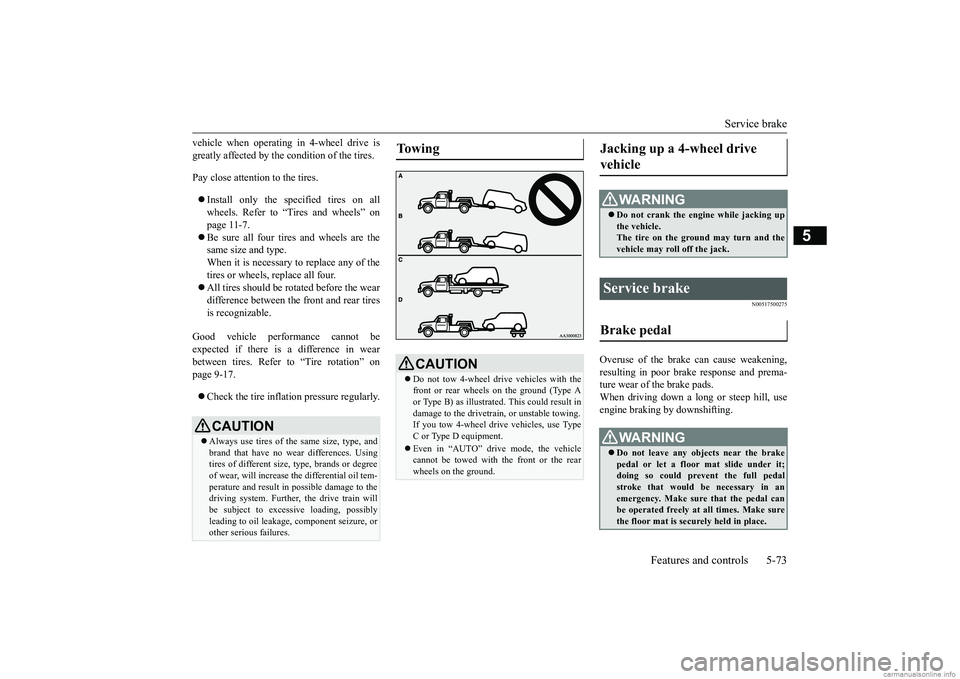
To w i n g
CAUTION Do not tow 4-wheel drive vehicles with the front or rear wheels on the ground (Type Aor Type B) as illustrated. This could result in damage to the drivetrain, or unstable towing. If you tow 4-wheel dr
ive vehicles, use Type
C or Type D equipment. Even in “AUTO” drive mode, the vehicle cannot be towed with the front or the rear wheels on the ground.
Jacking up a 4-wheel drive vehicle
WA R N I N G Do not crank the engine while jacking up the vehicle.The tire on the ground may turn and the vehicle may roll off the jack.
Service brake Brake pedal
WA R N I N G Do not leave any objects near the brake pedal or let a floor mat slide under it; doing so could prevent the full pedal stroke that would be necessary in anemergency. Make sure that the pedal can be operated freely at all times. Make sure the floor mat is securely held in place.
BK0252700US.bo
ok 73 ページ 2017年10月4日 水曜日 午後4時54分
Page 158 of 417
Anti-lock braking system
Features and controls 5-79
5
Operation of anti-lock braking system is not restricted situations where brakes are applied suddenly. This system may also prevent the wheels from locking whenyou drive over manh
oles, steel roadwork
plates, road markings, or any uneven road surface. When the anti-lock braking system is in use, you may feel the brake pedal vibrat- ing and hear a unique sound. It may alsofeel as if the pedal resists being pressed.In this situation, simply hold the brake pedal down firmly. Do not pump the brake, which will result in reducedbraking performance.
N00531601701
Warning light Warning display If there is a malfunction in the system, the anti-lock braking system warning light will come on and the warning display will appearon the information screen in the multi-infor- mation display. Under normal conditions,
the anti-lock brak-
ing system warning light only comes on when the ignition switch is turned to the “ON” position or the operation mode is put in ONand goes off a few seconds later.
N00531701669
Avoid hard braking and high-speed driv- ing. Stop the vehicle in a safe place.Test the system by restarting the engine and driving at a speed of approximately 12 mph (20 km/h) or higher.If the warning light/display then remains off during driving, there is no abnormal condition.
CAUTION The anti-lock braking system cannot prevent accidents. It is your responsibility to take safety precautions and to drive carefully. To prevent failure of the anti-lock braking system, be sure all four wheels and tires are the same size and the same type.NOTE
A whining sound is emitted from the engine compartment when dr
iving immediately
after starting the engine. These are the nor- mal sounds the anti-lock braking system makes when performing a self-check. It doesnot indicate a malfunction.
The anti-lock braking system can be used after the vehicle has reached a speed over approximately 6 mph (10 km/h). It stops working when the vehicle slows below 3 mph (5 km/h).
Anti-lock braking system warn- ing light / display
NOTE
CAUTION Any of the following indicates that the anti- lock braking system is not functioning and only the standard brak
e system is working.
(The standard brake system is functioning normally.) If this happens, take your vehicleto an authorized Mitsubishi Motors dealer or a repair facility of your choice. • When the ignition switch is in the “ON”position or the operation mode is put in ON, the warning light does not come on or itremains on and does not go off• The warning light comes on while driving• The warning display appears while driving
If the warning light/display illu- minate while driving If only the anti-lock braking sys- tem warning light/display illumi- nate
BK0252700US.bo
ok 79 ページ 2017年10月4日 水曜日 午後4時54分
Page 160 of 417
Active stability control (ASC) Features and controls 5-81
5
Warning light
Warning display If there is a malfunction in the system, the warning light will come on and the warningdisplay will appear on the information screen in the multi-information display. Under normal conditions, the warning lightcome on when the ignition switch is turned tothe “ON” position or the operation mode is put in ON, and goes off after the engine has started.
N00559100147
The Active stability control (ASC) takesoverall control of the anti-lock braking sys- tem, traction control function and skid control function to help maintain the vehicle’s control
and traction. Please read this section in con- junction with the page on the anti-lock brak- ing system, traction control function and skid control function. Anti-lock braking system
P.5-78
Traction control function
P.5-82
Skid control function
P.5-82
WA R N I N GDo not stop the engine while the vehicle is moving. Stopping the engine would make the steering wheel extremely hard to turn, possibly resulting in an accident.NOTE
During repeated full-lock turning of the steering wheel (for example, while you are manoeuvring the vehicle into a parking space), a protection function may be acti-vated to prevent overheating of the power steering system. This function will make the steering wheel gradually harder to turn. Inthis event, limit your tu
rning of the steering
wheel for a while. When the system has cooled down, the steering effort will returnto normal. If you turn the steering wheel while the vehi- cle is stationary with the headlights on, the headlights may become dim. This behavior is not abnormal. The headlights will return totheir original brightness after a short while.
Electric power steering system warning light/display
CAUTION If the warning display appears while the engine is running, have the vehicle inspected by an authorized Mitsubishi Motors dealer ora repair facility of your choice as soon as possible. It may become harder to turn the steering wheel.
Active stability control (ASC)
CAUTION Do not over-rely on the ASC. Even the ASC cannot prevent the natural laws of physics from acting on the vehicle. This system, like any other system, has limits and cannot helpyou to maintain traction and control of the vehicle in all circumstances. Reckless driv- ing can lead to accidents. It is the driver’sresponsibillty to drive carefully, This means taking into account the traffic, road and envi- ronmental conditions. Be sure to use the same specified type and size of tire on all four wheels. Otherwise, theASC may not work properly. Do not install any aftermarket limited slip differential (LSD) on your vehicle. The ASC may stop functioning properly.
BK0252700US.bo
ok 81 ページ 2017年10月4日 水曜日 午後4時54分
Page 168 of 417
Adaptive Cruise Control System (ACC) (if so equipped)
Features and controls 5-89
5
N00577000047
N00577100048
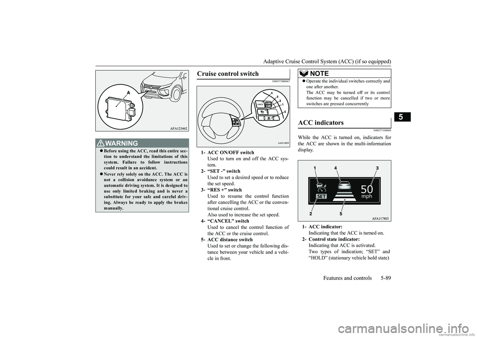
While the ACC is turned on, indicators for the ACC are shown in the multi-information display.
WA R N I N G Before using the ACC, read this entire sec- tion to understand the limitations of this system. Failure to follow instructions could result in an accident. Never rely solely on the ACC. The ACC is not a collision avoidance system or anautomatic driving system. It is designed to use only limited braking and is never a substitute for your safe and careful driv-ing. Always be ready to apply the brakes manually.
Cruise control switch
1- ACC ON/OFF switch
Used to turn on and off the ACC sys- tem.
2- “SET -” switch
Used to set a desired speed or to reduce the set speed.
3- “RES +” switch
Used to resume the control function after cancelling the ACC or the conven- tional cruise control.Also used to increase the set speed.
4- “CANCEL” switch
Used to cancel the control function ofthe ACC or the cruise control.
5- ACC distance switch
Used to set or change the following dis-tance between your vehicle and a vehi- cle in front.
NOTE
Operate the individual switches correctly and one after another. The ACC may be turned off or its control function may be cancelled if two or more switches are pressed concurrently
ACC indicators
1- ACC indicator:
Indicating that the ACC is turned on.
2- Control state indicator:
Indicating that ACC is activated. Two types of indication; “SET” and“HOLD” (stationary vehicle hold state)
BK0252700US.bo
ok 89 ページ 2017年10月4日 水曜日 午後4時54分
Page 173 of 417
Adaptive Cruise Control System (ACC) (if so equipped) 5-94 Features and controls
5
N00581500043
There are two ways to increase the set speed. The set speed will increase by 1 mph (1.6 km/h) every time you push up the“RES +” switch while the ACC is activated. If you hold the switch pushed up, the set speed increases in 5 mph (8 km/h) incre-ments.
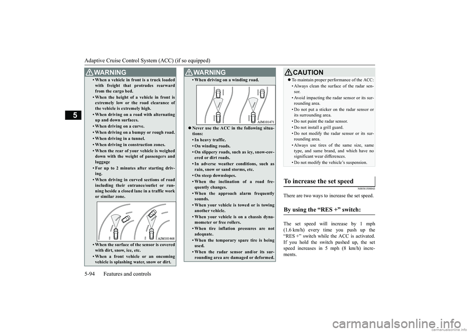
• When a vehicle in front is a truck loaded with freight that protrudes rearward from the cargo bed.• When the height of a vehicle in front isextremely low or the road clearance of the vehicle is extremely high.• When driving on a road with alternatingup and down surfaces.• When driving on a curve.• When driving on a bumpy or rough road.• When driving in a tunnel.• When driving in construction zones.• When the rear of your vehicle is weighed down with the weight of passengers and luggage• For up to 2 minutes after starting driv-ing.• When driving in curved sections of roadincluding their entrance/outlet or run- ning beside a closed lane in a traffic workor similar zone.• When the surface of the sensor is coveredwith dirt, snow, ice, etc.• When a front vehicle or an oncomingvehicle is splashing water, snow or dirt. WA R N I N G
• When driving on a winding road. Never use the ACC in the following situa- tions:• In heavy traffic.• On winding roads.• On slippery roads, such as icy, snow-cov- ered or dirt roads.• In adverse weather conditions, such asrain, snow or sand storms, etc.• On steep downslopes.• When the inclination of a road fre- quently changes.• When the approach alarm frequentlysounds.• When your vehicle is towed or is towinganother vehicle.• When your vehicle is on a chassis dyna-mometer or free rollers.• When tire inflation pressures are notadequate.• When the temporary spare tire is beingused.• When the radar sensor and/or its sur-rounding area are damaged or deformed.WA R N I N G
CAUTION To maintain proper performance of the ACC:• Always clean the surface of the radar sen- sor.• Avoid impacting the radar sensor or its sur-rounding area.• Do not put a sticker on the radar sensor orits surrounding area.• Do not paint the radar sensor.• Do not install a grill guard.• Do not modify the radar sensor or its sur- rounding area.• Always use tires of the same size, sametype, and same brand, and which have nosignificant wear differences.• Do not modify the vehicle’s suspension.
To increase the set speed
By using the “RES +” switch:
BK0252700US.bo
ok 94 ページ 2017年10月4日 水曜日 午後4時54分
Page 186 of 417
Forward Collision Mitigation sy
stem (FCM) (if so equipped) Features and controls 5-107
5
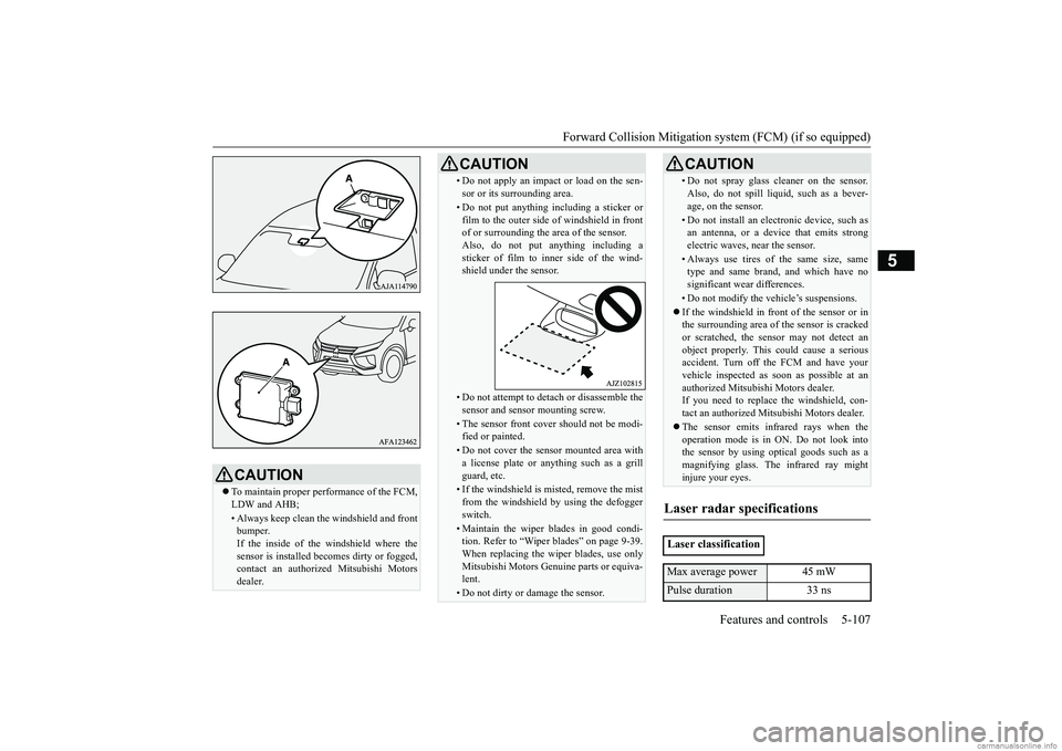
CAUTION To maintain proper performance of the FCM, LDW and AHB;• Always keep clean the windshield and frontbumper.If the inside of the windshield where the sensor is installed becomes dirty or fogged, contact an authorized Mitsubishi Motorsdealer.
• Do not apply an impact or load on the sen- sor or its surrounding area.• Do not put anything including a sticker or film to the outer side of windshield in frontof or surrounding the area of the sensor. Also, do not put anything including a sticker of film to inner side of the wind-shield under the sensor.• Do not attempt to detach or disassemble thesensor and sensor mounting screw.• The sensor front cover should not be modi-fied or painted.• Do not cover the sensor mounted area witha license plate or anything such as a grill guard, etc.• If the windshield is misted, remove the mistfrom the windshield by using the defogger switch.• Maintain the wiper blades in good condi-tion. Refer to “Wiper blades” on page 9-39. When replacing the wiper blades, use only Mitsubishi Motors Genuine parts or equiva-lent.• Do not dirty or damage the sensor.CAUTION
• Do not spray glass cleaner on the sensor. Also, do not spill liquid, such as a bever- age, on the sensor.• Do not install an electronic device, such asan antenna, or a device that emits strong electric waves, near the sensor.• Always use tires of the same size, sametype and same brand, and which have no significant wear differences.• Do not modify the vehicle’s suspensions. If the windshield in front of the sensor or in the surrounding area of the sensor is cracked or scratched, the sensor may not detect anobject properly. This could cause a serious accident. Turn off the FCM and have your vehicle inspected as soon as possible at anauthorized Mitsubishi Motors dealer. If you need to replace the windshield, con- tact an authorized Mitsubishi Motors dealer. The sensor emits infrared rays when the operation mode is in ON. Do not look intothe sensor by using opt
ical goods such as a
magnifying glass. The infrared ray might injure your eyes.
Laser radar specifications
Laser classificationMax average power 45 mWPulse duration 33 ns
CAUTION
BK0252700US.book
107 ページ 2017年10月4日 水曜日 午後4時54分
Page 197 of 417
Tire pressure monitoring system (TPMS) 5-118 Features and controls
5
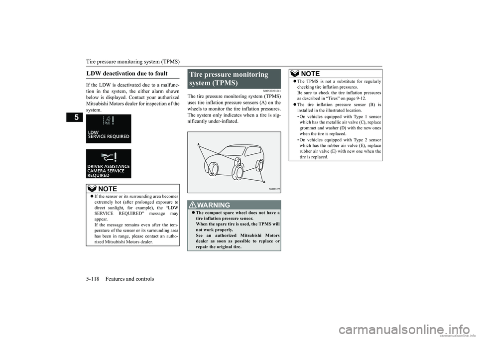
If the LDW is deactivated due to a malfunc- tion in the system, the either alarm shown below is displayed. Contact your authorizedMitsubishi Motors dealer for inspection of the system.
N00530201641
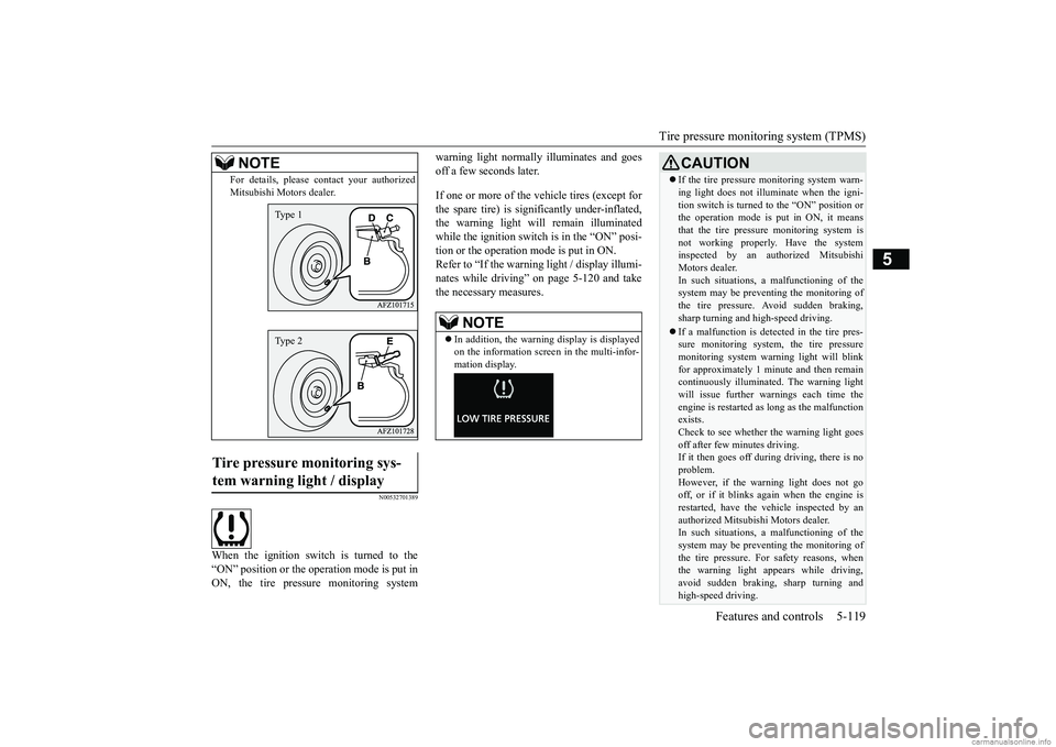
The tire pressure monitoring system (TPMS) uses tire inflation pressure sensors (A) on thewheels to monitor the tire inflation pressures. The system only indicates when a tire is sig- nificantly under-inflated.
LDW deactivation due to fault
NOTE
If the sensor or its surrounding area becomes extremely hot (after prolonged exposure to direct sunlight, for example), the “LDW SERVICE REQUIRED” message mayappear. If the message remains even after the tem- perature of the sensor or its surrounding areahas been in range, please contact an autho- rized Mitsubishi Motors dealer.
Tire pressure monitoring system (TPMS)
WA R N I N G The compact spare wheel does not have a tire inflation pressure sensor. When the spare tire is
used, the TPMS will
not work properly. See an authorized Mitsubishi Motors dealer as soon as possible to replace orrepair the original tire.
NOTE
The TPMS is not a substitute for regularly checking tire inflation pressures. Be sure to check the tire inflation pressures as described in “Tires” on page 9-12. The tire inflation pressure sensor (B) is installed in the illustrated location. • On vehicles equipped with Type 1 sensor which has the metallic air valve (C), replace grommet and washer (D) with the new oneswhen the tire is replaced. • On vehicles equipped with Type 2 sensor which has the rubber air valve (E), replace rubber air valve (E) with new one when the tire is replaced.
BK0252700US.book
118 ページ 2017年10月4日 水曜日 午後4時54分
Page 198 of 417
Tire pressure monitoring system (TPMS)
Features and controls 5-119
5
N00532701389
When the ignition switch is turned to the “ON” position or the operation mode is put inON, the tire pressure monitoring system
warning light normally illuminates and goes off a few seconds later. If one or more of the vehicle tires (except for the spare tire) is significantly under-inflated, the warning light will remain illuminatedwhile the ignition switch is in the “ON” posi- tion or the operation mode is put in ON. Refer to “If the warning light / display illumi-nates while driving” on page 5-120 and take the necessary measures.
For details, please contact your authorized Mitsubishi Motors dealer.
Tire pressure monitoring sys- tem warning light / display
NOTE
Type 1Type 2
NOTE
In addition, the warning display is displayed on the information screen in the multi-infor- mation display.
CAUTION If the tire pressure monitoring system warn- ing light does not illuminate when the igni- tion switch is turned to the “ON” position or the operation mode is put in ON, it means that the tire pressure monitoring system isnot working properly. Have the system inspected by an authorized Mitsubishi Motors dealer.In such situations,
a malfunctioning of the
system may be preventing the monitoring of the tire pressure. Avoid sudden braking,sharp turning and high-speed driving. If a malfunction is detected in the tire pres- sure monitoring system, the tire pressure monitoring system warning light will blink for approximately 1 minute and then remaincontinuously illuminated. The warning light will issue further warn
ings each time the
engine is restarted as long as the malfunctionexists. Check to see whether the warning light goes off after few minutes driving.If it then goes off during driving, there is no problem. However, if the warning light does not gooff, or if it blinks again when the engine is restarted, have the vehicle inspected by an authorized Mitsubishi Motors dealer. In such situations,
a malfunctioning of the
system may be preventing the monitoring ofthe tire pressure. For safety reasons, when the warning light appears while driving, avoid sudden braking, sharp turning andhigh-speed driving.
BK0252700US.book
119 ページ 2017年10月4日 水曜日 午後4時54分
Page 211 of 417

Multi Around Monitor (if so equipped) 5-132 Features and controls
5
N00587400031
Wide-angle view of the area behind the vehi- cle is displayed using the entire screen. Two different types of views are displayed on the left side and the right side respectively. Views of the surroundings of the vehicle and behind the vehicle are displayed.
Views of the passenger’s side of the vehicle and behind the vehicle are displayed.
Views of the surroundings of the vehicle and the front of the vehicle are displayed. Views of the passenger’s side of the vehicle and the front of the vehicle are displayed.
Types of views of the Multi Around Monitor
Wide-rear-view mode
Bird’s eye-view/Rear-view mode
Side-view/Rear-view mode
Bird’s eye-view/Front-view mode
Side-view/Front-view mode
BK0252700US.book
132 ページ 2017年10月4日 水曜日 午後4時54分