steering MITSUBISHI ECLIPSE CROSS 2019 (in English) User Guide
[x] Cancel search | Manufacturer: MITSUBISHI, Model Year: 2019, Model line: ECLIPSE CROSS, Model: MITSUBISHI ECLIPSE CROSS 2019Pages: 423, PDF Size: 75.41 MB
Page 82 of 423
![MITSUBISHI ECLIPSE CROSS 2019 (in English) User Guide Supplemental Restraint System (SRS) - airbag
Seat and restraint systems 4-45
4
• Steering wheel • Instrument panel[For vehicles sold in U.S.A.] To contact Mitsubishi Motors North America, Inc.cal MITSUBISHI ECLIPSE CROSS 2019 (in English) User Guide Supplemental Restraint System (SRS) - airbag
Seat and restraint systems 4-45
4
• Steering wheel • Instrument panel[For vehicles sold in U.S.A.] To contact Mitsubishi Motors North America, Inc.cal](/img/19/34870/w960_34870-81.png)
Supplemental Restraint System (SRS) - airbag
Seat and restraint systems 4-45
4
• Steering wheel • Instrument panel[For vehicles sold in U.S.A.] To contact Mitsubishi Motors North America, Inc.call 1-888-648-7820 or write to: Mitsubishi Motors North America, Inc. Customer Relations DepartmentP.O. Box 6400Cypress, CA 90630-0064 [For vehicles sold in Canada] To contact Mitsubishi Motor Sales of Canada, Inc. call 1-888-576-4878 or write to:Mitsubishi Motor Sales of Canada, Inc. Customer Relations Department P.O. Box 410094141 Dixie Road Mississauga, ON L4W 5C9NOTE
[For vehicles sold in Puerto Rico] To contact Mitsubishi Motor Sales of Caribbean, Inc. call 1-787-251-8715 or write to:Mitsubishi Motor Sales of Caribbean, Inc. Customer Service DepartmentP.O. Box 192216 SAN JUAN PR 00919-2216 [For vehicles sold in Guam] To contact Triple J Enterprises Inc. call (671) 649-3673 or write to: Triple J Enterprises, Inc.P.O. Box 6066 TAMUNING GUAM 96931 [For vehicles sold in Saipan] To contact Triple J Motorscall (670) 234-7133 or write to: Triple J Motors P.O. Box 500487SAIPAN, MP96950-0487
[For vehicles sold in American Samoa] To contact Pacific Marketing Inc. call 684 (699) 9140 or write to: Pacific Marketing, Inc.P.O. Box 698 PAGO PAGO, AMERICAN SAMOA AS, 96799
BK0266800US.bo
ok 45 ページ 2018年6月27日 水曜日 午後5時6分
Page 84 of 423
5
Features and controlsKeys ..........................................
.......................................................5-3
Electronic immobilizer (Anti-thef
t starting system) ........................5-4
Keyless entry system (if so equipped) ..............................................5-6 Free-hand Advanced Security Transmitter (F.A.S.T.-key) (if so equipped) .
.................................................
........................5-12
Door locks .......................
...............................................................5-31
Power door locks ............
...............................................................5-33
Child safety locks for r
ear door .....................................................5-34
Liftgate ......................................
.....................................................5-35
Theft-alarm system
................................................
........................5-37
Power window control
...........................................
........................5-39
Power panoramic sunroof (if
so equipped).....................................5-42
Parking brake ..................
...............................................................5-45
Steering wheel height and reach adjustment ..................................5-49 Inside rearview mirro
r ...........................................
........................5-50
Outside rearview mirr
ors ...............................................................5-52
Ignition switch ......
.................................................
........................5-56
Starting the engine
.................................................
........................5-57
Turbocharger operation
..........................................
........................5-59
Continuously variable trans
mission (CVT) ...................................5-59
S-AWC (Super-All Wheel Control) (if so equipped) .....................5-66 4-wheel drive operation
.........................................
........................5-68
Inspection and maintenance following rough road operation ........5-70Cautions on the handling of 4-wheel drive vehicles ......................5-71 Service brake ..................
...............................................................5-72
Brake auto hold (if so
equipped) ....................................................5-73
Hill start assist .......
.................................................
........................5-75
Brake assist system
................................................
........................5-76
Anti-lock braking syst
em .....................................
......................... 5-77
Electric power steering syst
em (EPS) ........................................... 5-79
Active stability control
(ASC) ....................
................................... 5-79
Cruise control ................
.................................................
............... 5-82
Adaptive Cruise Control System (ACC) (if so equipped) .............. 5-87 Forward Collision Mitigation system (FCM) (if so equipped) ...... 5-99 Blind Spot Warning (BSW) (with Lane Change Assist) (if so equipped) ..........
.................................................
............. 5-107
Rear Cross Traffic Alert (RCTA) (if so equipped) ....................... 5-113 Lane Departure Warning (LDW) (if so equipped) ....................... 5-117Tire pressure monitoring sy
stem (TPMS) ................................... 5-120
Rear-view camera ..........
.................................................
............. 5-125
Multi Around Monitor (if so
equipped)........................................ 5-127
Instrument cluster
.................................................
....................... 5-137
Multi-information disp
lay ....................................
....................... 5-138
Indicator light, warning light, and information screen display list
..............................................
....................... 5-158
Indicators .................................
.................................................... 5-178
Warning lights ................
.................................................
............. 5-179
Information screen disp
lay ........................
................................. 5-181
Head Up Display (HUD) (if
so equipped).................................... 5-182
Combination headlights and dimmer switch ............................... 5-186Headlight leveling switch (if
so equipped)................................... 5-194
Turn signal lever ..
.................................................
....................... 5-194
Hazard warning flasher
switch .................................................... 5-195
ECO mode switch ..........
.................................................
............. 5-196
Front fog light switch
...........................................
....................... 5-196
Wiper and washer swit
ch ......................................
....................... 5-196
BK0266800US.bo
ok 1 ページ 2018年6月27日 水曜日 午後5時6分
Page 85 of 423
5
Features and controlsElectric rear window defogge
r switch ......................................... 5-202
Heated steering wheel switch (i
f so equipped)............................. 5-203
Horn switch ..................
............................................................... 5-204
USB input terminal
..............................................
........................ 5-204
Sun visors .....................
............................................................... 5-205
12 V power outlets
..............................................
........................ 5-206
HomeLink
® Wireless Control System (if so equipped) ............... 5-207
Interior lights ......
.................................................
........................ 5-212
Storage spaces ..............
............................................................... 5-215
Drink holders ................
............................................................... 5-217
Bottle holders ...............
............................................................... 5-218
Cargo area cover (if so e
quipped) ............................................... 5-218
Assist grips ...................
............................................................... 5-220
Coat hooks ..............................
..................................................... 5-220
Luggage hooks .............
............................................................... 5-221
Convenient hook ....................
..................................................... 5-221
Luggage floor board
...........................................
........................ 5-221
BK0266800US.bo
ok 2 ページ 2018年6月27日 水曜日 午後5時6分
Page 107 of 423
Free-hand Advanced Security Transmitter (F.A.S.T.-key) (if so equipped) 5-24 Features and controls
5
3. If the engine still will not start, the engine could be flooded with too much gasoline. While depressing the brake pedal, push the accelerator pedal all the way downand hold it there, then press the engine switch to crank the engine. If the engine does not start after 5 to 6 seconds, pushthe engine switch to stop cranking the engine, and release the accelerator pedal. Put the operation mode in OFF. Wait afew seconds, and then press the engineswitch to crank the engine again while depressing the brake pedal, but do not push the accelerator pedal. If the enginefails to start, repeat these procedures. If the engine still will not start, contact your local Mitsubishi Motors dealer or a repairfacility of your choice for assistance.
Startability of the engine with an ambient temperature of -22 °F (-30 °C) or lower When the ambient temperature is -22 °F (-30°C) or lower, it may not be possible to start from a standstill even with the selector lever in the “D” (DRIVE) or “R” (REVERSE)position. This phenomenon occurs because the trans- axle has not warmed up sufficiently; it doesnot indicate a problem. If this occurs, place the selector lever in the “P” (PARK) position and let the engine idle for at least 10 minutes.
The transaxle will warm up, and you will be able to start normally. Do not leave the vehicle during warm-up operation.
N00568201053
1. Stop the vehicle.2. Fully engage the parking brake while depressing the brake pedal. 3. Move the selector lever to the “P”(PARK) position, and then press the engine switch to stop the engine.
N00568301113
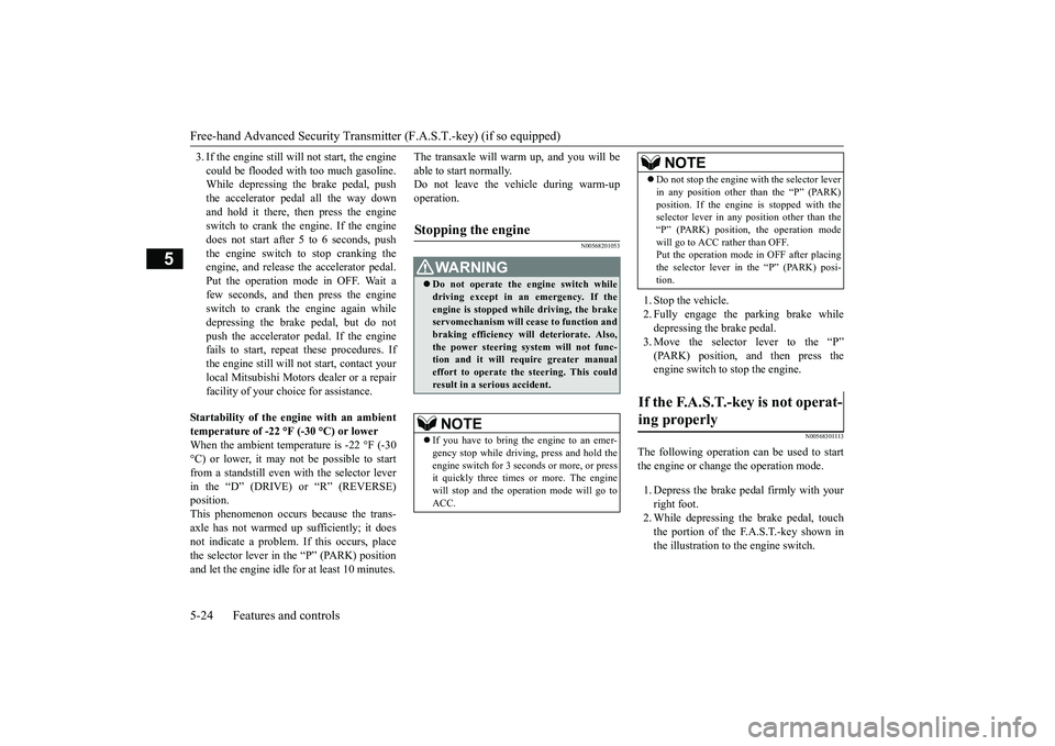
The following operation can be used to start the engine or change the operation mode. 1. Depress the brake pe
dal firmly with your
right foot. 2. While depressing the brake pedal, touch the portion of the F.A.S.T.-key shown inthe illustration to the engine switch.
Stopping the engine
WA R N I N G Do not operate the engine switch while driving except in an emergency. If the engine is stopped while driving, the brake servomechanism will cease to function andbraking efficiency will deteriorate. Also, the power steering system will not func- tion and it will require greater manualeffort to operate the steering. This could result in a serious accident.NOTE
If you have to bring the engine to an emer- gency stop while driving, press and hold the engine switch for 3 seco
nds or more, or press
it quickly three times or more. The enginewill stop and the operation mode will go to ACC.
Do not stop the engine with the selector lever in any position other than the “P” (PARK) position. If the engine is stopped with the selector lever in any position other than the “P” (PARK) position, the operation modewill go to ACC rather than OFF. Put the operation mode in OFF after placing the selector lever in the “P” (PARK) posi-tion.
If the F.A.S.T.-key is not operat- ing properly
NOTE
BK0266800US.bo
ok 24 ページ 2018年6月27日 水曜日 午後5時6分
Page 132 of 423
Steering wheel height and reach adjustment
Features and controls 5-49
5
Warning light (yellow) Warning display If there is a malfunction in the system, the warning light will come on. In addition, thewarning display appears on the informationscreen in the multi-information display.
Under normal conditions, the warning light only comes on when the ignition switch is turned to the “ON” position or the operation mode is put in ON and goes off a few secondslater.
N00511501241
To adjust the steering wheel to the desiredposition, move the lever upward or down-
If the acceleration of the vehicle seems abnormally slow after the vehicle has been parked with the Electric parking brake applied in cold weather, stop the vehicle in a safe place, then apply and release the Elec-tric parking brake. If the vehicle acceleration is still slow, contact the nearest authorized Mitsubishi Motors dealer or a repair facilityof your choice.NOTE
When the ignition switch or the operation mode is other than ON, the parking brake cannot be released. If the Electric parking brake does not auto- matically release, it may be released by man-ual operation. When the selector lever is other than “P” (PARK) position, if you try to release the Electric parking brake without depressing the brake pedal, the warning display willappear.CAUTION
If you start driving without releasing the Electric parking brake, the warning display will appear. If the driver’s foot contacts the accelerator pedal in the condition that the Electric park-ing brake can release by an automatic opera- tion, the Electric parking brake may be released automatically.
Warning light/display
NOTE
CAUTION When the Electric parking brake warning light (yellow) does not illuminate or remains illuminated when the ignition switch isturned to the “ON” position or the operation mode is put in ON, or comes on while driv- ing, the Electric parking brake may not beapplied or released. Immediately contact the nearest authorized Mitsubishi Motors dealer or a repair facilityof your choice. For details, refer to “Electric parking brake warning light (yellow)” on page 5-179.When parking your vehicle while the Elec- tric parking brake warning light (yellow) is illuminated, park the vehicle on level andstable ground, move the selector lever to the “P” (PARK) position and place chocks, blocks, stones behind and in front of the tiresto prevent the vehicle from moving.
Steering wheel height and reach adjustment
BK0266800US.bo
ok 49 ページ 2018年6月27日 水曜日 午後5時6分
Page 133 of 423
Inside rearview mirror 5-50 Features and controls
5
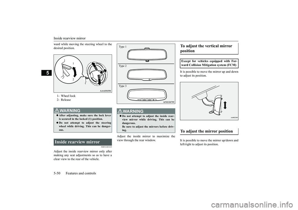
ward while moving the steering wheel to the desired position.
N00511601415
Adjust the inside rear
view mirror only after
making any seat adjustme
nts so as to have a
clear view to the rear of the vehicle.
Adjust the inside mirror to maximize the view through the rear window.
It is possible to move
the mirror up and down
to adjust its position. It is possible to move the mirror up/down and left/right to adjust its position.
1- Wheel lock 2- ReleaseWA R N I N G After adjusting, make sure the lock lever is secured in the locked (1) position. Do not attempt to adjust the steering wheel while driving. This can be danger- ous.
Inside rearview mirror
1 2
WA R N I N G Do not attempt to adjust the inside rear- view mirror while driving. This can be dangerous. Be sure to adjust the mirrors before driv-ing.Type 1 Type 2 Type 3
To adjust the vertical mirror position Except for vehicles equipped with For- ward Collision Mitigation system (FCM)To adjust the mirror position
BK0266800US.bo
ok 50 ページ 2018年6月27日 水曜日 午後5時6分
Page 140 of 423
Starting the engine
Features and controls 5-57
5
N00550901253
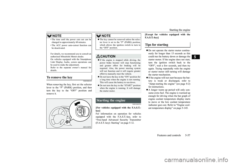
When removing the key,
first set the selector
lever to the “P” (PARK) position, and thenturn the key to the “OFF” position and remove it.
N00512601874
[For vehicles equipped with the F.A.S.T.- key]For information on operation for vehicles equipped with the F.A.S.T.-key, refer to “Free-hand Advanced Security Transmitter(F.A.S.T.-key): Starting” on page 5-12.
[Except for vehicles equipped with the F. A . S . T. - k e y ] Do not operate the starter motor continu- ously for longer than 15 seconds as thiscould run the battery down or damage the starter motor. If the engine does not start, turn the ignition switch back to the“OFF”, wait a few seconds, and then tryagain. Trying repeatedly with the engine or starter motor still
turning will damage
the starter mechanism. If the engine will not start because the bat- tery is weak or discharged, refer to “Jump-starting the engine” (on page 8-2)for instructions. A longer warm up period will only con- sume extra fuel. The engine is warmed upenough for driving when the bar graph of engine coolant temperature display starts to move or the low coolant temperatureindicator goes out. Refer to “Engine cool- ant temperature display” on page 5-145.
• The time until the power cuts out can be changed to approximately 60 minutes. • The ACC power auto-cutout function can be deactivated. For details, we recommend you to consult an authorized Mitsubishi Motors dealer. On vehicles equipped with the Smartphone Link Display Audio, screen operations canbe used to make the adjustment. Refer to the separate owner’s manual for details.
To remove the key
NOTE
NOTE
The key cannot be removed unless the selec- tor lever is set to the “P” (PARK) position, which allows the ignition switch to turn to the “OFF” position.CAUTION If the engine is stopped while driving, the power brake booster will stop functioning and greater effort for braking will be required. Also, the power steering systemwill not function and it will require greater effort to manually steer the vehicle. Do not leave the key in the “ON” position for a long time when the engine is not running. This will cause the battery to run down. Do not turn the key to the “START” position when the engine is running. It will damagethe starter motor.
Starting the engine
Tips for starting
BK0266800US.bo
ok 57 ページ 2018年6月27日 水曜日 午後5時6分
Page 142 of 423
Turbocharger operation
Features and controls 5-59
5
lever in the “D” (DRIVE) or “R” (REVERSE) position. This occurs because the transaxle has not warmed up sufficiently; it does not indicate aproblem. If this occurs, place the selector lever in the “P” (PARK) position and let the engine idle for at least 10 minutes.The transaxle will warm up, and you will be able to start normally. Do not leave the vehicle during warm-upoperation.
N00537301090
N00560201073
The CVT will automatically and continuously change its gear ratio depending on road anddriving conditions. This helps achieve smooth driving and excellent fuel efficiency. If your vehicle is equipped with the spor-tronic steering wheel paddle shifter, you can manually shift the transmission up and down. Refer to “Sports mode” on page 5-63. The transmission prevents unnecessary upshifts even when the accelerator pedal is released and ensures smooth driving. According to the condi
tions, the transmission
will automatically shift to a lower gear ratioto achieve stronger engine braking. This may help reduce your need to use the service brake.
N00560301104
As an additional safe
ty precaution, models
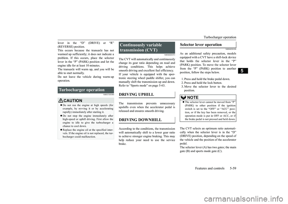
equipped with a CVT have a shift-lock devicethat holds the selector lever in the “P” (PARK) position. To move the selector lever from the “P” (PARK) position to anotherposition, follow the steps below. 1. Press and hold the brake pedal down. 2. Press and hold the lock button. 3. Move the selector lever to the desired position.
The CVT selects an optimum ratio automati- cally when the selector lever is in the “D” (DRIVE) position, depending on the speed of the vehicle and the position of the acceleratorpedal. The selector lever (A) has two gates; the main gate (B) and sports mode gate (C).
Turbocharger operation
CAUTION Do not run the engine at high speeds (for example, by revving it or by acceleratingrapidly) immediately after starting it. Do not stop the engine immediately after high-speed or uphill driving. First allow the engine to idle to give the turbocharger a chance to cool down. Replace the engine oil at the specified inter- vals. If the engine oil is not replaced, the tur-bocharger could malfunction.
Continuously variable transmission (CVT) DRIVING UPHILL DRIVING DOWNHILL
Selector lever operation
NOTE
The selector lever cannot be moved from “P” (PARK) to other position if the ignitionswitch is set to the “OFF” or “ACC” posi- tion, or if the key has been removed, or the operation mode is put in OFF or ACC, or ifthe brake pedal is not
pressed and held down.
BK0266800US.bo
ok 59 ページ 2018年6月27日 水曜日 午後5時6分
Page 146 of 423
Continuously variable transmission (CVT)
Features and controls 5-63
5
At this position, the transmission is disen- gaged. It is the same as the neutral position ona manual transaxle and
should be used when
the vehicle is not moving for an extended length of time during driving, such as in atraffic jam.
This position is used for most city and high- way driving. The transmission will automati-cally and continuously change its gear ratio depending on road and driving conditions.
N00560701124
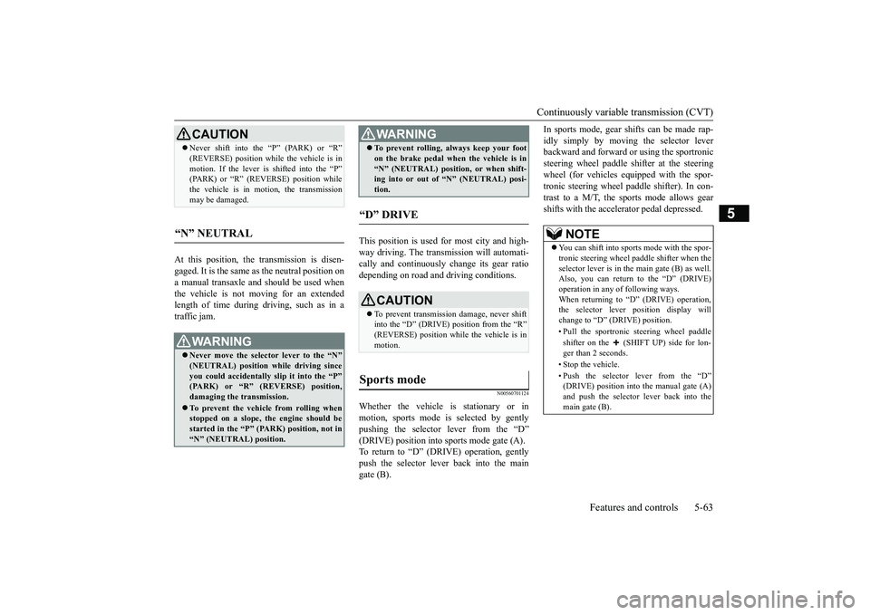
Whether the vehicle is stationary or inmotion, sports mode is selected by gently pushing the selector lever from the “D”(DRIVE) position into sports mode gate (A). To return to “D” (DRIVE) operation, gently push the selector lever back into the maingate (B).
In sports mode, gear shifts can be made rap- idly simply by moving the selector lever backward and forward or using the sportronic steering wheel paddle sh
ifter at the steering
wheel (for vehicles equipped with the spor- tronic steering wheel paddle shifter). In con- trast to a M/T, the sports mode allows gearshifts with the accelerator pedal depressed.
CAUTION Never shift into the “P” (PARK) or “R” (REVERSE) position while the vehicle is in motion. If the lever is shifted into the “P” (PARK) or “R” (REVERSE) position while the vehicle is in motion, the transmissionmay be damaged.
“N” NEUTRAL
WA R N I N G Never move the selector lever to the “N” (NEUTRAL) position while driving since you could accidentally slip it into the “P” (PARK) or “R” (REVERSE) position,damaging the transmission. To prevent the vehicle from rolling when stopped on a slope, the engine should be started in the “P” (PARK) position, not in“N” (NEUTRAL) position.
To prevent rolling, always keep your foot on the brake pedal when the vehicle is in “N” (NEUTRAL) position, or when shift- ing into or out of “N” (NEUTRAL) posi- tion.
“D” DRIVE
CAUTION To prevent transmission damage, never shift into the “D” (DRIVE) position from the “R”(REVERSE) position while the vehicle is in motion.
Sports mode
WA R N I N G
NOTE
You can shift into sports mode with the spor- tronic steering wheel paddle shifter when the selector lever is in the main gate (B) as well.Also, you can return to the “D” (DRIVE) operation in any of following ways. When returning to “D” (DRIVE) operation,the selector lever position display will change to “D” (DRIVE) position. • Pull the sportronic steering wheel paddle shifter on the (SHIFT UP) side for lon- ger than 2 seconds. • Stop the vehicle.• Push the selector lever from the “D” (DRIVE) position into the manual gate (A)and push the selector lever back into the main gate (B).
BK0266800US.bo
ok 63 ページ 2018年6月27日 水曜日 午後5時6分
Page 147 of 423

Continuously variable transmission (CVT) 5-64 Features and controls
5
N00560901083
In sports mode, the currently selected shift range is displayed on the information screenin the multi-information display.
N00560801109
1-
(SHIFT UP) Transmission shifts up once by eachoperation.
2-
(SHIFT DOWN) Transmission shifts down once by eachoperation.CAUTION In sports mode, the
driver must execute
upward shifts in accordance with prevailing road conditions, taking care to keep the engine speed below the tachometer’s redzone. Repeated continuous operation of the selec- tor lever or the sportronic steering wheel paddle shifter will continuously switch shift position. Shift ranges may not change when the lateral paddle shifters are operated at the same time.
NOTE
Shift ranges can only be selected in a for- ward direction from 1st to 8th. To reverse or park the vehicle, move the selector lever to the “R” (REVERSE) or “P” (PARK) posi- tion. To maintain good running performance, the transmission may refuse to perform anupshift when the selector lever or the spor- tronic steering wheel paddle shifter on the “ (SHIFT UP)” side is pulled at certain vehicle speeds. Also, to prevent over-revving of the engine, the transmission may refuse toperform a downshift when the selector lever or the sportronic steering wheel paddle shifter on the “ (SHIFT DOWN)” side is pulled at certain vehicle speeds. When this happens, a buzzer sounds to indicate that a downshift is not going to take place. Downward shifts are made automatically when the vehicle slows down. Before the vehicle stops, 1st gear is automatically selected. The upward shift may be made automatically in sports mode when the engine speed risesand approaches the tachometer’s red zone.
Sports mode display
Operation of the CVT
CAUTION Before selecting a position with the engine running and the vehicle stationary, firmlydepress the brake pedal to prevent the vehi- cle from creeping. The vehicle will begin to move as soon as theCVT is engaged, especially when the engine speed or idle speed is high, or with the air conditioning operating.Do not release the brake pedal until you are ready to drive away. Depress the brake pedal
with the right foot at
all times. Using the left foot could cause driver move-ment delay in case of an emergency. To prevent sudden acceleration, never run the engine at high revolutions when shifting from the “P” (PARK) or “N” (NEUTRAL).
BK0266800US.bo
ok 64 ページ 2018年6月27日 水曜日 午後5時6分