ABS MITSUBISHI ECLIPSE CROSS 2019 Owner's Manual (in English)
[x] Cancel search | Manufacturer: MITSUBISHI, Model Year: 2019, Model line: ECLIPSE CROSS, Model: MITSUBISHI ECLIPSE CROSS 2019Pages: 423, PDF Size: 75.41 MB
Page 75 of 423
Supplemental Restraint System (SRS) - airbag 4-38 Seat and restraint systems
4
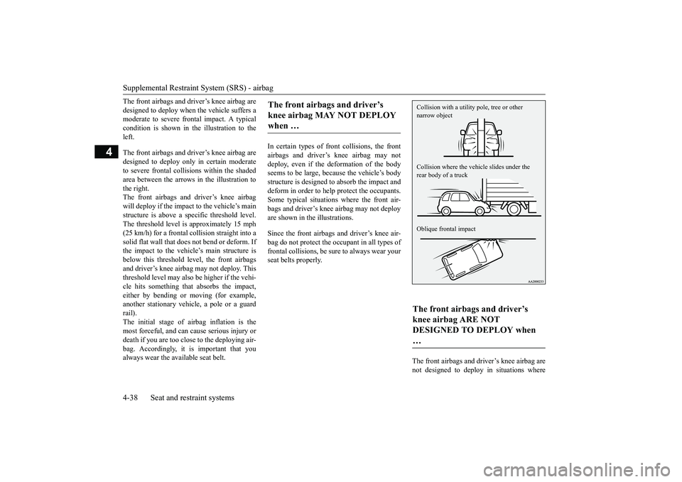
The front airbags and driver’s knee airbag are designed to deploy when the vehicle suffers a moderate to severe frontal impact. A typical condition is shown in the illustration to theleft. The front airbags and driver’s knee airbag are designed to deploy only in certain moderate to severe frontal collisions within the shadedarea between the arrows in the illustration to the right. The front airbags and driver’s knee airbagwill deploy if the impact to the vehicle’s mainstructure is above a specific threshold level. The threshold level is approximately 15 mph (25 km/h) for a frontal collision straight into asolid flat wall that does not bend or deform. If the impact to the vehicle’s main structure is below this threshold level, the front airbagsand driver’s knee airbag may not deploy. This threshold level may also be higher if the vehi- cle hits something that absorbs the impact,either by bending or moving (for example, another stationary vehicle, a pole or a guard rail).The initial stage of airbag inflation is the most forceful, and can cause serious injury or death if you are too close to the deploying air-bag. Accordingly, it is important that you always wear the available seat belt.
In certain types of front collisions, the front airbags and driver’s knee airbag may not deploy, even if the deformation of the body seems to be large, because the vehicle’s bodystructure is designed to absorb the impact and deform in order to help protect the occupants. Some typical situations where the front air-bags and driver’s knee airbag may not deployare shown in the illustrations. Since the front airbags and driver’s knee air- bag do not protect the occupant in all types of frontal collisions, be sure to always wear yourseat belts properly.
The front airbags and driver’s knee airbag are not designed to deploy in situations where
The front airbags and driver’s knee airbag MAY NOT DEPLOY when …
The front airbags and driver’s knee airbag ARE NOT DESIGNED TO DEPLOY when … Collision with a utility
pole, tree or other
narrow object Collision where the vehi
cle slides under the
rear body of a truck Oblique frontal impact
BK0266800US.bo
ok 38 ページ 2018年6月27日 水曜日 午後5時6分
Page 80 of 423
Supplemental Restraint System (SRS) - airbag
Seat and restraint systems 4-43
4
The seat belts in your vehicle are your pri- mary means of protection in an accident. The SRS side airbags and curtain airbags are designed to provide additional protection.Therefore, for your safety and the safety of all occupants, be sure to always wear your seat belts properly. In certain types of side
collisions, the side air-
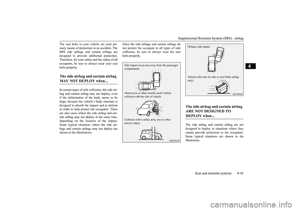
bag and curtain airbag may not deploy, even if the deformation of the body seems to be large, because the vehicle’s body structure isdesigned to absorb the impact and to deform in order to help protect the occupants. There are also cases where the side airbag and cur-tain airbag may not deploy at the same time, depending on the location of the impact. Some typical situations where the side air-bags and curtain airbags may not deploy are shown in the illustrations.
Since the side airbags and curtain airbags do not protect the occupant in all types of side collisions, be sure to always wear the seat belts properly.
The side airbag and curtain airbag are not designed to deploy in situations where they cannot provide protection to the occupants.Some typical situations are shown in the illustration.
The side airbag and curtain airbag MAY NOT DEPLOY when...
Side impact in an area
away from the passenger
compartment Motorcycle or other similar small vehicle collision with the side of vehicle Collision with a utility
pole, tree or other
narrow object
The side airbag and curtain airbag ARE NOT DESIGNED TO DEPLOY when... Oblique side impact Vehicle rolls onto its side
or roof (Side airbag
only)
BK0266800US.bo
ok 43 ページ 2018年6月27日 水曜日 午後5時6分
Page 149 of 423
S-AWC (Super-All Wheel Control) (if so equipped) 5-66 Features and controls
5
N00541301091
S-AWC is an integrated vehicle dynamics control system that helps enhance driving performance, cornering performance, and vehicle stability over a wide range of drivingconditions through integrated management of the electronically controlled 4WD, the AYC (Active Yaw Control), the ABS and the ASC. The electronically controlled 4WD is a sys- tem that improves acceleration performance and stability performance by controllingfront-rear distribution of driving torque with
operating the electronic control coupling arranged in the rear differential assembly. The AYC is a system with a yaw control function, that controls the left-right driv- ing/braking force using the brakes. The yaw control function is a function that enhances vehicle cornering performance and vehicle stability with management of vehicleturning power (yaw moment) by controlling the drive power difference of the left and right wheels and the braking force when thevehicle does not turn in response to steering input, such as when the steering wheel is turned quickly or when driving on slipperyroad.
N00542401099
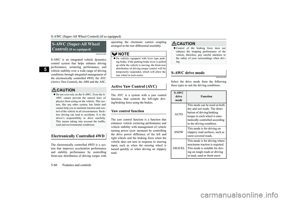
Select the drive mode from the followingthree types to suit the driving conditions.
S-AWC (Super-All Wheel Control)
(if so equipped)
CAUTION Do not over-rely on the S-AWC. Even the S- AWC cannot prevent the natural laws ofphysics from acting on the vehicle. This sys- tem, like any other system, has limits and cannot help you to maintain traction and con-trol of the vehicle in all circumstances. Reck- less driving can lead to accidents. It is the driver’s responsibility to drive carefully.This means taking into account the traffic, road and environmental conditions.
Electronically Controlled 4WD
NOTE
On vehicles equipped with lever type park- ing brake, if the parking brake lever is pulled up while the vehicle is moving, the front-reardistribution of driving torque control will be temporarily suspended, which will allow the rear wheel to lock easier.
Active Yaw Control (AYC)
Yaw control function
CAUTION Control of the braking force does not enhance the stopping performance of the vehicle, therefore, pay careful attention to the safety of your surroundings when driv- ing.
S-AWC drive mode
S-AWC drive mode
Function
AUTO
This mode can be used on both dry and wet roads. The distri-bution of driving/braking torque to each wheel is auto- matically controlled according to the driving condition.
SNOW
This mode is for driving on slippery road surfaces, such as snow-covered roads.
GRAVEL
This mode is for driving where maximum traction is required. This mode is suitable for driv- ing on rough roads or driving in mud, sand or fresh snow.
BK0266800US.bo
ok 66 ページ 2018年6月27日 水曜日 午後5時6分
Page 153 of 423
Inspection and maintenance foll
owing rough road operation
5-70 Features and controls
5
Your vehicle may not provide sufficient hill climbing ability and engine braking on steep slope. Avoid driving on steep slopes eventhough the vehicle is an 4-wheel drive vehi- cle.
N00537800085
If the electrical circuits become wet, furtheroperation of the vehicle will be impossible; therefore, avoid driving through water unlessabsolutely necessary. If driving through water is unavoidable, use the following procedure: Check the depth of the water and the terrain before attempting to drive through it. Drive
slowly to avoid creating excessive water splashing.
N00530700085
After operating the vehicle in rough road con- ditions, be sure to perform the following inspection and maintenance procedures: Check that the vehicle has not been dam- aged by rocks, gravel, etc.
• If the engine coolant temperature display
flashes on the information screen in the multi-information display or the engine power drops suddenly.Refer to “Engine overheating” on page 8-4.• If the “ ” warning display and “SLOW DOWN” or the “ ” warning display and “SERVICE REQUIRED” appear on the information screen in the multi-information display.Refer to “Warning display” on page 5-62.WA R N I N G When attempting to rock your vehicle out of a stuck position, be sure that the area around the vehicle is clear of people andphysical objects. The rocking motion may cause the vehicle to suddenly launch for- ward/backward, causing injury or dam-age to nearby people or objects.NOTE
Avoid sudden braking, sudden acceleration and sharp turning; such operations could result in the vehicle becoming stuck.CAUTION
If the vehicle becomes stuck in sandy or muddy roads, it can often be moved with a rocking motion. Move the selector lever alternately between the “D” (DRIVE) and “R” (REVERSE) positions while pressinglightly on the accelerator pedal. Driving on rough road can cause rust on the vehicle; wash the vehicle thoroughly as soon as possible after such use.
Climbing/descending sharp grades Driving through water
NOTE
CAUTION Never drive through water that is deep enough to cover wheel hubs, axles or exhaust pipe. Do not change the selector lever posi-tion while driving through water. Frequent driving through water can adversely affect the life span of the vehicle;consult an authorized Mitsubishi Motors dealer or a repair facility of your choice and take the necessary measures to prepare,inspect, and repair the vehicle. After driving through water, apply the brakes to be sure they are functioning properly. If the brakes are wet and not functioning prop- erly, dry them out by driving slowly whilelightly depressing the brake pedal. Inspect each part of the vehicle carefully.
Inspection and maintenance following rough road opera-tion
BK0266800US.bo
ok 70 ページ 2018年6月27日 水曜日 午後5時6分
Page 173 of 423
Adaptive Cruise Control System (ACC) (if so equipped) 5-90 Features and controls
5
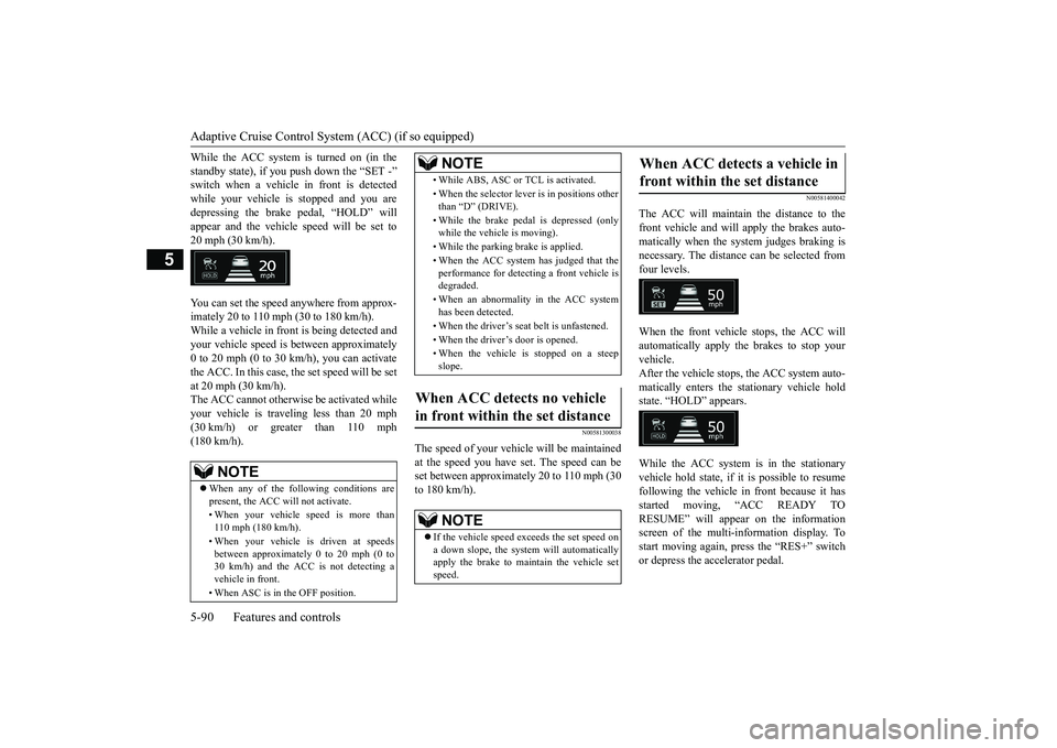
While the ACC system is turned on (in the standby state), if you push down the “SET -” switch when a vehicle in front is detected while your vehicle is stopped and you aredepressing the brake pedal, “HOLD” will appear and the vehicle speed will be set to 20 mph (30 km/h). You can set the speed anywhere from approx- imately 20 to 110 mph (30 to 180 km/h). While a vehicle in front is being detected and your vehicle speed is between approximately0 to 20 mph (0 to 30 km/h), you can activatethe ACC. In this case, the set speed will be set at 20 mph (30 km/h). The ACC cannot otherwise be activated whileyour vehicle is traveling less than 20 mph (30 km/h) or greater than 110 mph (180 km/h).
N00581300038
The speed of your vehicle will be maintainedat the speed you have set. The speed can be set between approximately 20 to 110 mph (30 to 180 km/h).
N00581400042
The ACC will maintain the distance to thefront vehicle and will apply the brakes auto- matically when the system judges braking is necessary. The distance can be selected fromfour levels. When the front vehicle stops, the ACC will automatically apply the brakes to stop yourvehicle. After the vehicle stops, the ACC system auto- matically enters the stationary vehicle holdstate. “HOLD” appears. While the ACC system is in the stationary vehicle hold state, if it is possible to resume following the vehicle in front because it has started moving, “ACC READY TORESUME” will appear on the information screen of the multi-information display. To start moving again, press the “RES+” switchor depress the accelerator pedal.
NOTE
When any of the following conditions are present, the ACC will not activate. • When your vehicle speed is more than 110 mph (180 km/h). • When your vehicle is driven at speeds between approximately 0 to 20 mph (0 to30 km/h) and the ACC is not detecting a vehicle in front. • When ASC is in the OFF position.
• While ABS, ASC or TCL is activated. • When the selector lever is in positions other than “D” (DRIVE). • While the brake pedal is depressed (only while the vehicle is moving). • While the parking brake is applied. • When the ACC system has judged that the performance for detecting a front vehicle is degraded. • When an abnormality in the ACC system has been detected. • When the driver’s seat belt is unfastened. • When the driver’s door is opened.• When the vehicle is stopped on a steep slope.
When ACC detects no vehicle in front within the set distance
NOTE
If the vehicle speed exceeds the set speed on a down slope, the system will automaticallyapply the brake to maintain the vehicle set speed.NOTE
When ACC detects a vehicle in front within the set distance
BK0266800US.bo
ok 90 ページ 2018年6月27日 水曜日 午後5時6分
Page 178 of 423
Adaptive Cruise Control System (ACC) (if so equipped)
Features and controls 5-95
5
N00581700074
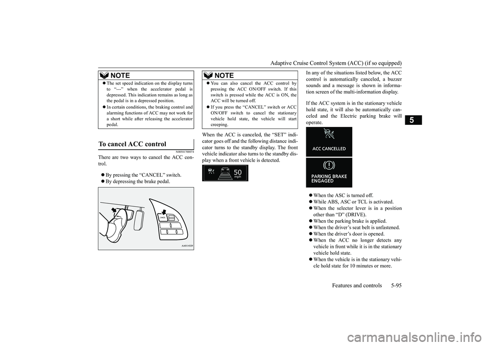
There are two ways to cancel the ACC con- trol. By pressing the “CANCEL” switch. By depressing the brake pedal.
When the ACC is canceled, the “SET” indi- cator goes off and the following distance indi-cator turns to the standby display. The front vehicle indicator also turns to the standby dis- play when a front vehicle is detected.
In any of the situations listed below, the ACC control is automatically canceled, a buzzer sounds and a message is shown in informa- tion screen of the multi-information display. If the ACC system is in the stationary vehicle hold state, it will also be automatically can- celed and the Electric parking brake will operate. When the ASC is turned off. While ABS, ASC or TCL is activated. When the selector lever is in a position other than “D” (DRIVE). When the parking brake is applied. When the driver’s seat belt is unfastened. When the driver’s door is opened. When the ACC no longer detects any vehicle in front while it is in the stationaryvehicle hold state. When the vehicle is in the stationary vehi- cle hold state for 10 minutes or more.
NOTE
The set speed indication on the display turns to “---” when the accelerator pedal is depressed. This indication remains as long as the pedal is in a depressed position. In certain conditions, the braking control and alarming functions of ACC may not work for a short while after releasing the acceleratorpedal.
To cancel ACC control
NOTE
You can also cancel the ACC control by pressing the ACC ON/OFF switch. If this switch is pressed while
the ACC is ON, the
ACC will be turned off. If you press the “CANCEL” switch or ACC ON/OFF switch to cancel the stationary vehicle hold state, the vehicle will startcreeping.
BK0266800US.bo
ok 95 ページ 2018年6月27日 水曜日 午後5時6分
Page 180 of 423
Adaptive Cruise Control System (ACC) (if so equipped)
Features and controls 5-97
5
moving again, push up the “RES +” switch or depress the accelerator pedal.
N00581900047
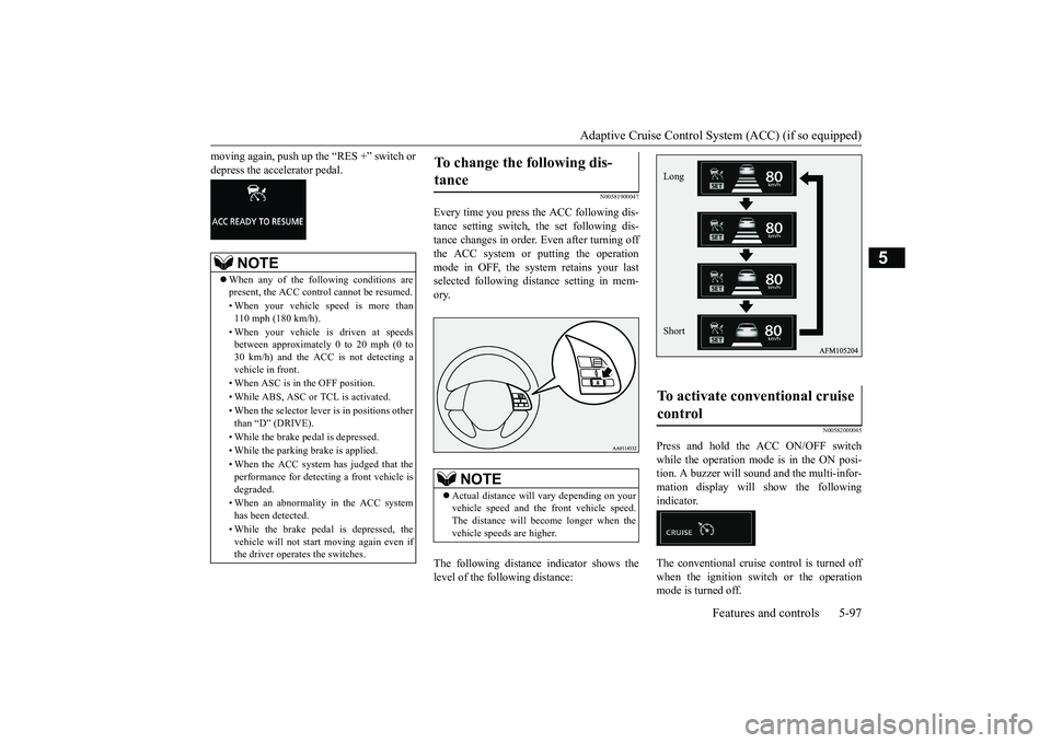
Every time you press the ACC following dis-tance setting switch, the set following dis- tance changes in order. Even after turning off the ACC system or putting the operationmode in OFF, the system retains your last selected following distance setting in mem- ory. The following distance indicator shows the level of the following distance:
N00582000045
Press and hold the ACC ON/OFF switch while the operation mode is in the ON posi-tion. A buzzer will sound and the multi-infor- mation display will show the following indicator. The conventional cruise control is turned off when the ignition switch or the operationmode is turned off.
NOTE
When any of the following conditions are present, the ACC control cannot be resumed. • When your vehicle speed is more than 110 mph (180 km/h). • When your vehicle is driven at speeds between approximately 0 to 20 mph (0 to 30 km/h) and the ACC is not detecting avehicle in front. • When ASC is in the OFF position.• While ABS, ASC or TCL is activated. • When the selector lever is in positions other than “D” (DRIVE). • While the brake pedal is depressed. • While the parking brake is applied.• When the ACC system has judged that the performance for detecting a front vehicle isdegraded. • When an abnormality in the ACC system has been detected. • While the brake pedal is depressed, the vehicle will not start moving again even if the driver operates the switches.
To change the following dis- tance
NOTE
Actual distance will vary depending on your vehicle speed and the front vehicle speed. The distance will become longer when thevehicle speeds are higher.
To activate conventional cruise control
Long Short
BK0266800US.bo
ok 97 ページ 2018年6月27日 水曜日 午後5時6分
Page 320 of 423

Trailer towing
Driving safety 6-15
6
Avoid jerky or sudden maneuvers. Signal well in advance. Towing a trailer puts additional burden on the engine and transaxle, which may cause over- heating. Following are some suggestions to reduce overheating: When towing at high altitudes, engine coolant and automatic transaxle fluid will overheat at a lower temperature than at normal altitudes.If you turn your engine off immediately after towing at high altitude on steep uphill grades, your vehicle may show signs similar to over-heating. To avoid this
, let the engine run
while parked (preferably on level ground)
with the automatic transaxle in the “P” (PARK) position for a few minutes before turning the engine off. If the engine coolant temperature indica- tor flashes on the information screen in the multi-information display or the engine power drops suddenly, refer to “Engine overheating” on page 8-4. If the warning display or warning display illuminates, refer to “Warning dis- play” on page 5-62.
Reduce speed and downshift before you start down a long or steep
downgrade. If you don’t
downshift, prolonged or frequent applicationof the brakes can cause reduced braking effi- ciency and performance. You can tow in “D” (DRIVE) position. How- ever, you may want to shift the selector leverto the 3rd or a lower position, under heavy loads or hilly conditions. Always place chocks or blocks under both the vehicle and trailer wheels when parking. Be sure that the parking brake is firmly set and
that the selector lever is in the “P” (PARK) position. Avoid parking on a hill with a trailer, but if it cannot be avoided, do so only after performing the following: 1. Apply the brakes and keep them applied. 2. Have someone place chocks or blocks under both the vehicle and trailer wheels. 3. When the chocks or blocks are in place,release your brakes slowly until the chocks or blocks absorb the load. 4. Apply the parking brake firmly.5. Set the selector lever to the “P” (PARK)position and turn off the engine.
When restarting out after parking on a hill: 1. Check that the selector lever is set to the “P” (PARK) position. 2. Start the engine. Be sure to keep the brakepedal depressed. 3. Set the selector lever to the “D” (DRIVE) position or “R” (REVERSE) position.4. Release the parking brake and brake pedal and slowly pull or
back away from the
chocks or blocks. Stop and apply yourbrakes. 5. Have someone retrieve the chocks or blocks.
Overheating
Cause of over-
heating
Solution
Air conditioning on Turn off Highway speeds Reduce speed Going up hills
Select lower gear posi- tion
Stop-and-go city traffic
With the vehicle stopped, shift to the “N” (NEUTRAL) position and idle the engine at high idle.
Driving on hills Parking
BK0266800US.bo
ok 15 ページ 2018年6月27日 水曜日 午後5時6分
Page 360 of 423
Fuel Pump Shut-off System
For emergencies 8-13
8
When driving on a road covered with snow or ice, use snow tires. Tire chains cannot be used on your vehicle. Theremay be state or local regulations about using snow tires. Always check the regu- lations in your local area before usingthem. Refer to “Snow tires” on page 9-18 and “Tire chains” on page 9-18. Drive slowly. Do not make sudden starts or stops, sharp turns, or slam on thebrakes. Allow extra distance between your vehi- cle and the vehicle in front of you, andavoid sudden braking. If a skid occurs when the accelerator pedal is depressed, take your foot off thepedal. Steer gently in the direction of the skid. Your vehicle is equipped with an anti-lock braking system (ABS). Hold the brake pedal down firmly and keep it depressed. Do not pump the brake pedal which willresult in reduced braking performance. After parking on snowy or icy roads, it may be difficult to move your vehicle dueto the brake being frozen. Depress the accelerator pedal little by little to move the vehicle when safe to do so.
Drive as slow as poss
ible when driving on
bumpy, rutted roads or over potholes.
N00860600031
WA R N I N G When trying to rock your vehicle out of a stuck position, make sure that there are no people nearby. The rocking motion can make your vehicle suddenly lurch forward or backward, and injure any bystanders.
On wet roads
CAUTION Avoid flooded roads. Water is often deeper than it looks, and you could be seriously hurt by driving into flood water. When driving in rain, on water-covered roads, or through a car wash, water could getinto the brake discs and make them fail tem- porarily. In such cases, lightly press the brake pedal to see if they are working prop-erly. If they are not, press the pedal lightly several times while driving to dry the brake pads or linings, then check them again. When driving in rain, a layer of water may form between the tires and the road surface(hydroplaning). This loosens your tires’ grip on the road, making it difficult to steer or brake properly. When driving on a wet road:• Drive your vehicle at a safe speed.• Do not drive on worn tires.• Always keep the tires at the correct infla- tion pressures.
On snowy or icy roads
CAUTION Do not depress the accelerator pedal rapidly. The vehicle could start moving when it breaks free from the ice, possibly resulting in an accident.
On a bumpy or rutted road
CAUTION Driving on bumpy, rutted roads or over pot- holes can damage the tires and wheels. Wheels with low-profile tires or under- inflated tires are especially at risk for dam-age.
Fuel Pump Shut-off System
WA R N I N G Before attempting to restart the engine after a collision, always inspect the ground under the vehicle for leaking fuel. If a fuel leak is found or a fuel odor is detected, donot restart the engine.
BK0266800US.bo
ok 13 ページ 2018年6月27日 水曜日 午後5時6分
Page 374 of 423
Tires
Vehicle care and maintenance 9-13
9
Sidewall: portion of a tire between the tread and bead. Section width: the li
near distance between
the exteriors of the sidewalls of aninflated tire, excluding elevations due to labeling, decoration, or protective bands. Bead: the part of the tire that is made of steel wires, wrapped or reinforced by ply cords and that is shaped to fit the rim. Ply: a layer of rubber-coated parallel cords. Cord: the strands forming the plies in the tire. Rim: a metal support for a tire or a tire and tube assembly upon which the tire beads are seated. Rim diameter: nominal diameter of the bead seat. Groove: the space between two adjacent tread ribs.
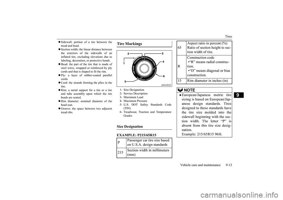
EXAMPLE: P215/65R15Tire Markings 1- Size Designation 2- Service Description 3- Maximum Load4- Maximum Pressure 5- U.S. DOT Safety Standards Code
(TIN)
6- Treadwear, Traction and Temperature
Grades
Size Designation P
Passenger car tire size based on U.S.A. design standards
215
Section width in millimeters (mm)
65
Aspect ratio in percent (%) Ratio of section height to sec- tion width of tire.
R
Construction code •“R” means radial construc- tion. •“D” means diagonal or bias construction.
15 Rim diameter in inches (in)
NOTE
European/Japanese metric tire sizing is based on European/Jap-anese design standards. Tires designed to these standards have the tire size molded into thesidewall beginning with the sec- tion width. The letter “P” is absent from this tire size desig-nation. Example: 215/65R15 96H.
BK0266800US.bo
ok 13 ページ 2018年6月27日 水曜日 午後5時6分