201 MITSUBISHI ECLIPSE CROSS 2020 (in English) User Guide
[x] Cancel search | Manufacturer: MITSUBISHI, Model Year: 2020, Model line: ECLIPSE CROSS, Model: MITSUBISHI ECLIPSE CROSS 2020Pages: 427, PDF Size: 78.05 MB
Page 108 of 427
Free-hand Advanced Security Transmit
ter (F.A.S.T.-key) (if so equipped)
Features and controls 5-27
5
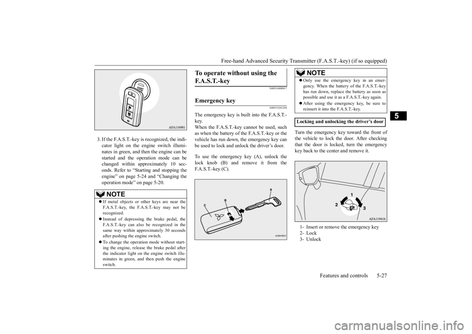
3. If the F.A.S.T.-key is recognized, the indi- cator light on the engine switch illumi-nates in green, and then the engine can be started and the operation mode can be changed within approximately 10 sec-onds. Refer to “Starting and stopping the engine” on page 5-24 and “Changing the operation mode” on page 5-20.
N00514800017 N00515201204
The emergency key is built into the F.A.S.T.- key. When the F.A.S.T.-key cannot be used, such as when the battery of the F.A.S.T.-key or thevehicle has run down, the emergency key canbe used to lock and unlock the driver’s door. To use the emergency key (A), unlock the lock knob (B) and remove it from the F.A.S.T.-key (C).
Turn the emergency key toward the front of the vehicle to lock th
e door. After checking
that the door is locked, turn the emergencykey back to the center and remove it.
NOTE
If metal objects or other keys are near the F.A.S.T.-key, the F.A.S.T.-key may not be recognized. Instead of depressing the brake pedal, the F.A.S.T.-key can also be recognized in the same way within approximately 30 secondsafter pushing the engine switch. To change the operation mode without start- ing the engine, release the brake pedal after the indicator light on the engine switch illu- minates in green, and then push the engineswitch.
To operate without using the F. A . S . T. - k e y
Emergency key
NOTE
Only use the emergency key in an emer- gency. When the battery of the F.A.S.T.-key has run down, replace the battery as soon as possible and use it as a F.A.S.T.-key again. After using the emergency key, be sure to reinsert it into the F.A.S.T.-key.
Locking and unlocking the driver’s door 1- Insert or remove the emergency key 2- Lock 3- Unlock
BK0277700US.bo
ok 27 ページ 2019年3月8日 金曜日 午前9時23分
Page 109 of 427

Free-hand Advanced Security Transmitter (F.A.S.T.-key) (if so equipped) 5-28 Features and controls
5
N00529601140
The electronic immobilizer is designed to sig- nificantly reduce the possibility of vehicle theft. The purpose of the system is to immo- bilize the vehicle if an invalid start isattempted. A valid start attempt can only be achieved (subject to certain conditions) using a F.A.S.T.-key “registered” to the immobi-lizer system.All of the keys provided with your new vehi- cle have been programmed to the vehicle’s electronics.
N00561000042
Only the F.A.S.T.-keys that have been pro- grammed to the vehicle’s electronics can be used to start the vehicle. If you lose the F.A.S.T.-key, you can order a F.A.S.T.-key from your authorized Mitsubishi Motors dealer by referring to the key number. To prevent vehicle theft, take your vehicleand the remaining F.A.S.T.-keys to an autho-
rized Mitsubishi Motors dealer to have the ID codes reprogrammed.
N00561101066
To add a F.A.S.T.-key, you must already havetwo registered F.A.S.T.-keys. You need to register the ID code to the vehicle. Registering the ID code can be done by yourauthorized Mitsubishi Motors dealer. Or itcan be done by yourself (except for vehicles sold in Canada). For you to register the ID code yourself, fol-low the “Customer F.A.S.T.-key program- ming” procedure below. If you choose to have your authorizedMitsubishi Motors dealer register the ID code, take your vehicle and all remaining F.A.S.T.-keys to your authorized MitsubishiMotors dealer.
N00561201315
You can program new F.A.S.T.-keys to thesystem if you have two valid (already regis- tered) F.A.S.T.-keys and a blank (not regis- tered) F.A.S.T.-key. For F.A.S.T.-key programming, follow the procedures below. 1. Open the driver’s door. 2. While carrying the first valid F.A.S.T.- key, put the operation mode in ON. (Per- form the following procedure within30 seconds.) 3. With the first valid F.A.S.T.-key, press the UNLOCK button for 4 to 8 seconds andpress the LOCK button during this time. 4. Release in sequence the LOCK and UNLOCK buttons within 8 seconds ofpressing the LOCK button in step 3. (Per- form the following procedure within 30 seconds.)
Electronic immobilizer (Anti- theft starting system)
NOTE
If the engine does not start, contact an autho- rized Mitsubishi Motors dealer.
Replacement F.A.S.T.-keys
Additional F.A.S.T.-keys
NOTE
You are provided with two F.A.S.T.-keys, but you may register up to four F.A.S.T.-keys. You can obtain blank F.A.S.T.-keys specially cut for your vehicle from your Mitsubishi Motors dealer.
Customer F.A.S.T.-key program- ming (Except for vehicles sold in Canada)
NOTE
Keep the driver’s door open until F.A.S.T.- key programming is finished. Do not open orclose other doors.
BK0277700US.bo
ok 28 ページ 2019年3月8日 金曜日 午前9時23分
Page 116 of 427
Door locks
Features and controls 5-35
5
N00509201586
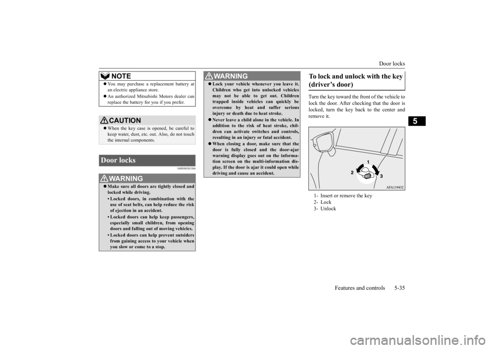
Turn the key toward the front of the vehicle to lock the door. After ch
ecking that the door is
locked, turn the key back to the center and remove it.
NOTE
You may purchase a replacement battery at an electric appliance store. An authorized Mitsubishi Motors dealer can replace the battery for you if you prefer.CAUTION When the key case is opened, be careful to keep water, dust, etc.
out. Also, do not touch
the internal components.
Door locks
WA R N I N G Make sure all doors are tightly closed and locked while driving.• Locked doors, in combination with theuse of seat belts, can help reduce the risk of ejection in an accident.• Locked doors can help keep passengers,especially small children, from opening doors and falling out of moving vehicles.• Locked doors can help prevent outsidersfrom gaining access to your vehicle when you slow or come to a stop.
Lock your vehicle whenever you leave it. Children who get into unlocked vehicles may not be able to get out. Children trapped inside vehicles can quickly be overcome by heat and suffer seriousinjury or death due to heat stroke. Never leave a child alone in the vehicle. In addition to the risk of heat stroke, chil- dren can activate switches and controls, resulting in an injury or fatal accident. When closing a door, make sure that the door is fully closed and the door-ajarwarning display goes out on the informa- tion screen on the multi-information dis- play. If the door is ajar it could open whiledriving and cause an accident.WA R N I N G
To lock and unlock with the key (driver’s door) 1- Insert or remove the key 2- Lock 3- Unlock
BK0277700US.bo
ok 35 ページ 2019年3月8日 金曜日 午前9時23分
Page 122 of 427
Theft-alarm system
Features and controls 5-41
5
N00510201267
The theft-alarm system is designed to provide protection from unauthorized entry into thevehicle. This system is operated in three stages: the first is the “armed” stage, the sec- ond is the “alarm” stage,
and third is the “dis-
armed” stage. If triggered, the system provides both audible and visual alarm sig- nals.
N00510301239
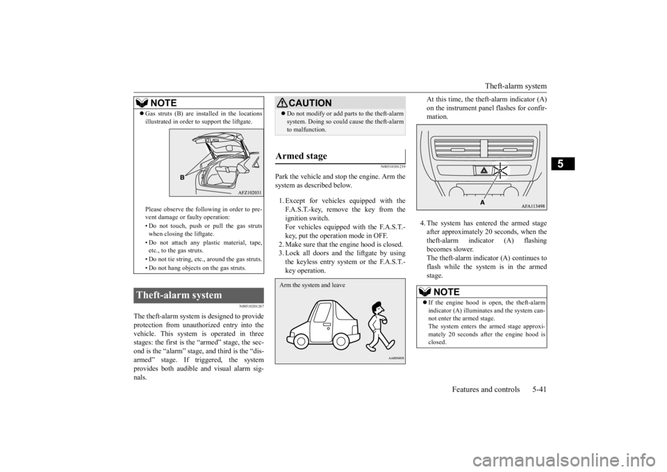
Park the vehicle and stop the engine. Arm thesystem as described below. 1. Except for vehicles equipped with the F.A.S.T.-key, remove the key from the ignition switch. For vehicles equipped with the F.A.S.T.-key, put the operation mode in OFF. 2. Make sure that the engine hood is closed. 3. Lock all doors and the liftgate by usingthe keyless entry system or the F.A.S.T.- key operation.
At this time, the theft-alarm indicator (A) on the instrument panel flashes for confir- mation. 4. The system has entered the armed stage after approximately 20 seconds, when thetheft-alarm indicator (A) flashing becomes slower. The theft-alarm indicator (A) continues toflash while the system is in the armedstage.
NOTE
Gas struts (B) are installed in the locations illustrated in order to support the liftgate. Please observe the following in order to pre- vent damage or faulty operation: • Do not touch, push or pull the gas struts when closing the liftgate. • Do not attach any plastic material, tape, etc., to the gas struts. • Do not tie string, etc., around the gas struts. • Do not hang objects
on the gas struts.
Theft-alarm system
CAUTIONDo not modify or add parts to the theft-alarm system. Doing so could cause the theft-alarm to malfunction.
Armed stage Arm the system and leave
NOTE
If the engine hood is open, the theft-alarm indicator (A) illuminates and the system can- not enter the armed stage.The system enters the armed stage approxi- mately 20 seconds after the engine hood is closed.
BK0277700US.bo
ok 41 ページ 2019年3月8日 金曜日 午前9時23分
Page 137 of 427
Outside rearview mirrors 5-56 Features and controls
5
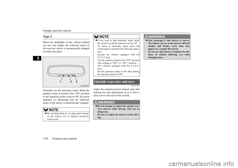
When the headlights of the vehicles behind you are very bright, the reflection factor of the rearview mirror is automatically changedto reduce the glare. Normally, use the automatic mode. When the ignition switch is turned to the “ON” position or the operation mode is put in ON, the greenindicator (1) illuminates and the reflectionfactor of the mirror is automatically changed.
N00512201232
Adjust the outside rearview mirrors only aftermaking any seat adjustments so as to have a clear view to the rear of the vehicle.
Ty p e 3
NOTE
Do not hang items on, or spray glass cleaner on the sensors (2), as reduced sensitivity could result.
If you want to stop automatic mode, press the switch (3) and the indicator will go off. To return to automatic mode, press the switch again or perform the following opera- tion.[Except for vehicles equipped with the F. A . S . T. - k e y ] Turn the ignition switch to the “ON” positionafter turning to “OFF” or “ACC” position. [For vehicles equipped with the F.A.S.T.- key]Put the operation mode in ON after putting the operation mode in OFF.
Outside rearview mirrors
WA R N I N G Do not attempt to adjust the outside rear- view mirrors while driving. This can be dangerous. Be sure to adjust the mirrors before driv-ing.NOTE
Your passenger’s side mirror is convex. The objects you see in the mirror will look smaller and farther away than they appear in a regular flat mirror. Do not use this mirror to estimate the dis-tance of vehicles following you when changing lanes.WA R N I N G
BK0277700US.bo
ok 56 ページ 2019年3月8日 金曜日 午前9時23分
Page 138 of 427
Outside rearview mirrors
Features and controls 5-57
5
N00549101196
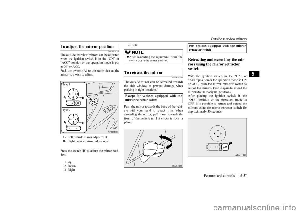
The outside rearview mirrors can be adjusted when the ignition switch is in the “ON” or“ACC” position or the operation mode is put in ON or ACC. Push the switch (A) to the same side as themirror you wish to adjust. Press the switch (B) to adjust the mirror posi- tion.
N00549201269
The outside mirror can be retracted towards the side window to prevent damage whenparking in tight locations. Push the mirror towards the back of the vehi- cle with your hand to retract it in. Whenextending the mirror, pull it out towards the front of the vehicle until it clicks to lock in place.
With the ignition switch in the “ON” or “ACC” position or the
operation mode in ON
or ACC, push the mirror retractor switch toretract the mirrors. Push it again to extend themirrors to their original positions. After placing the ignition switch in the “OFF” position or the operation mode inOFF, it is possible to retract and extend the mirrors using the mirror retractor switch for approximately 30 seconds.
To adjust the mirror position L- Left outside mirror adjustment R- Right outside mirror adjustment 1- Up 2- Down 3- RightType 1 Type 2
4- Left
NOTE
After completing the adjustment, return the switch (A) to the center position.
To retract the mirror Except for vehicles equipped with the mirror retractor switch
For vehicles equipped with the mirrorretractor switchRetracting and extending the mir- rors using the mirror retractor switch
BK0277700US.bo
ok 57 ページ 2019年3月8日 金曜日 午前9時23分
Page 144 of 427
Turbocharger operation
Features and controls 5-63
5
lever in the “D” (DRIVE) or “R” (REVERSE) position. This occurs because the transaxle has not warmed up sufficiently; it does not indicate aproblem. If this occurs, place the selector lever in the “P” (PARK) position and let the engine idle for at least 10 minutes.The transaxle will warm up, and you will be able to start normally. Do not leave the vehicle during warm-upoperation.
N00537301090
N00560201103
The CVT will automatically and continuously change its gear ratio depending on road anddriving conditions. This helps achieve smooth driving and excellent fuel efficiency. Also you can manually shift the transmissionup and down. Refer to “Sports mode” on page 5-67. The transmission prevents unnecessary upshifts even when the accelerator pedal is released and ensures smooth driving. According to the condi
tions, the transmission
will automatically shift to a lower gear ratio to achieve stronger engine braking. This mayhelp reduce your need to use the service brake.
N00560301104
As an additional safe
ty precaution, models
equipped with a CVT have a shift-lock device
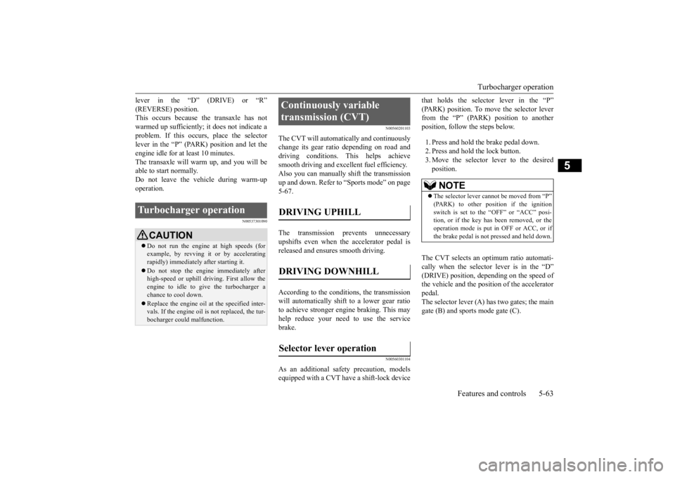
that holds the selector lever in the “P” (PARK) position. To move the selector lever from the “P” (PARK) position to another position, follow the steps below. 1. Press and hold the brake pedal down. 2. Press and hold the lock button. 3. Move the selector lever to the desired position.
The CVT selects an optimum ratio automati- cally when the selector lever is in the “D”(DRIVE) position, depending on the speed of the vehicle and the position of the accelerator pedal.The selector lever (A) has two gates; the main gate (B) and sports mode gate (C).
Turbocharger operation
CAUTION Do not run the engine at high speeds (for example, by revving it or by acceleratingrapidly) immediately after starting it. Do not stop the engine immediately after high-speed or uphill driving. First allow the engine to idle to give the turbocharger a chance to cool down. Replace the engine oil at the specified inter- vals. If the engine oil is not replaced, the tur-bocharger could malfunction.
Continuously variable transmission (CVT) DRIVING UPHILL DRIVING DOWNHILL Selector lever operation
NOTE
The selector lever cannot be moved from “P” (PARK) to other position if the ignition switch is set to the “OFF” or “ACC” posi- tion, or if the key has been removed, or theoperation mode is put in OFF or ACC, or if the brake pedal is not
pressed and held down.
BK0277700US.bo
ok 63 ページ 2019年3月8日 金曜日 午前9時23分
Page 164 of 427
Anti-lock braking system
Features and controls 5-83
5
N00531701715
Avoid hard braking and high-speed driv-
ing. Stop the vehicle in a safe place.
Test the system by restarting the engine
and driving at a speed of approximately
12 mph (20 km/h) or higher.
If the warning light/display then remains
off during driving, there is no abnormal
condition.
However, if the warning light/display do
not disappear, or if they come on again
when the vehicle is driven, have the vehi-
cle checked by an authorized Mitsubishi
Motors dealer or repair facility of your
choice as soon as possible. Warning light
or
Warning display
The anti-lock braking system and brake force
distribution function may not work, so hard
braking could make the vehicle unstable.
Avoid hard braking and high-speed driving.
Stop the vehicle in a safe place and contact an
authorized Mitsubishi Motors dealer or repair
facility of your choice.
N00529201104
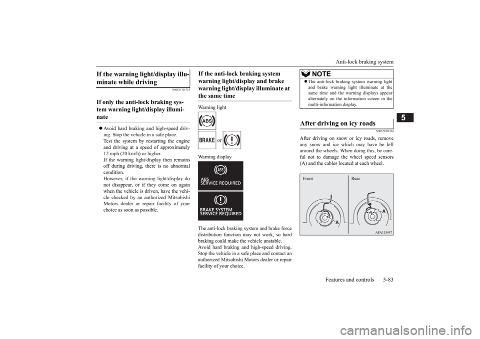
After driving on snow or icy roads, remove
any snow and ice which may have be left
around the wheels. When doing this, be care-
ful not to damage the wheel speed sensors
(A) and the cables located at each wheel.
If the warning light/display illu-
minate while driving If only the anti-lock braking sys-
tem warning light/display illumi-
nate
If the anti-lock braking system
warning light/display and brake
warning light/display illuminate at
the same time
NOTE
The anti-lock braking system warning light
and brake warning light illuminate at the
same time and the warning displays appear
alternately on the information screen in the
multi-information display.After driving on icy roads Front Rear
BK0277700US.book 83 ページ 2019年3月12日 火曜日 午前9時34分
Page 207 of 427
Tire pressure monitoring system (TPMS) 5-126 Features and controls
5
The alarm shown below is displayed if the system becomes temporarily unavailable due to the dirty windshield of the sensor portion.After having cleaned the windshield, the sys- tem will automatically return to operation. If the alarm continues showing, there is a pos-sibility that the LDW has a malfunction. Con- tact an authorized Mitsubishi Motors dealer for inspection of the sensor.
If the LDW is deactivated due to a malfunc- tion in the system, the either alarm shown below is displayed. Contact your authorizedMitsubishi Motors dealer for inspection of the system.
N00530201641
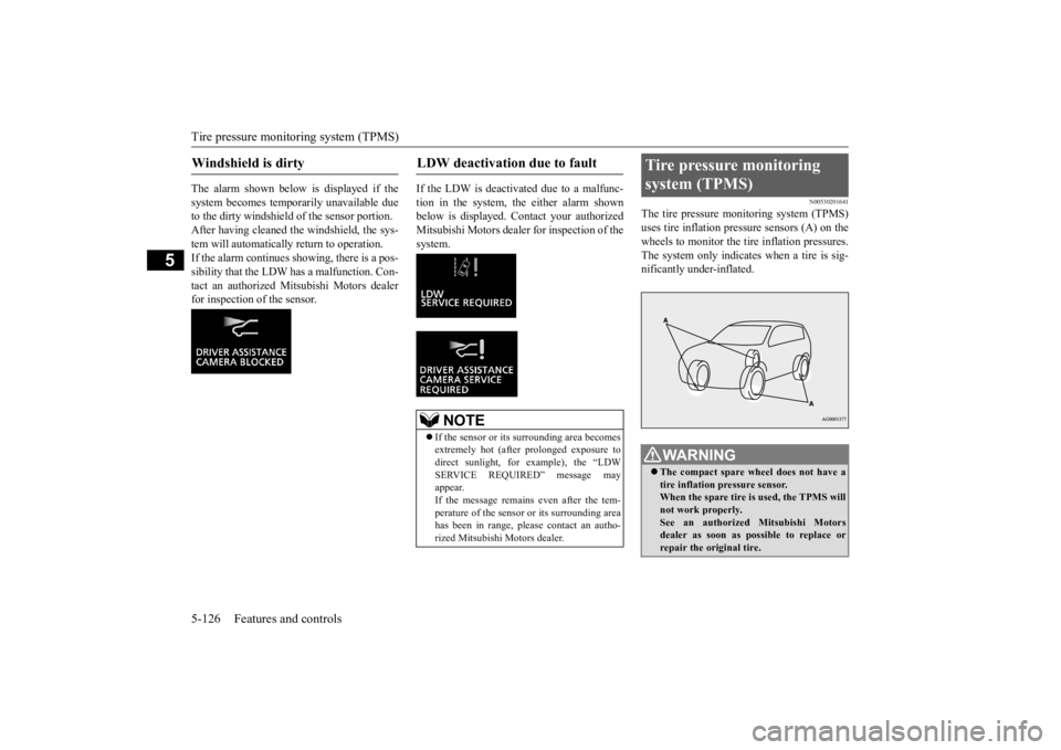
The tire pressure monitoring system (TPMS) uses tire inflation pressure sensors (A) on thewheels to monitor the tire inflation pressures. The system only indicates when a tire is sig- nificantly under-inflated.
Windshield is dirty
LDW deactivation due to fault
NOTE
If the sensor or its surrounding area becomes extremely hot (after prolonged exposure to direct sunlight, for example), the “LDWSERVICE REQUIRED” message may appear. If the message remains even after the tem-perature of the sensor or its surrounding area has been in range, please contact an autho- rized Mitsubishi Motors dealer.
Tire pressure monitoring system (TPMS)
WA R N I N G The compact spare wheel does not have a tire inflation pressure sensor. When the spare tire is
used, the TPMS will
not work properly. See an authorized Mitsubishi Motors dealer as soon as possible to replace orrepair the original tire.
BK0277700US.book
126 ページ 2019年3月8日 金曜日 午前9時23分
Page 212 of 427
Rear-view camera
Features and controls 5-131
5
Rules and Industry Canada licence-exempt RSS standard(s). Operation is subject to the following two con- ditions. This device may not cause harmful inter- ference. This device must accept any interference received, including interference that maycause undesired operation.
N00546201330
When the selector lever is in the “R”(REVERSE) position with the ignition switchin the “ON” position, or the operation mode is put in ON, the rear-view image will be dis- played on the screen of the Smartphone LinkDisplay Audio. When the selector lever is shifted out of the “R” (REVERSE) position, the rear-viewimage will go off.
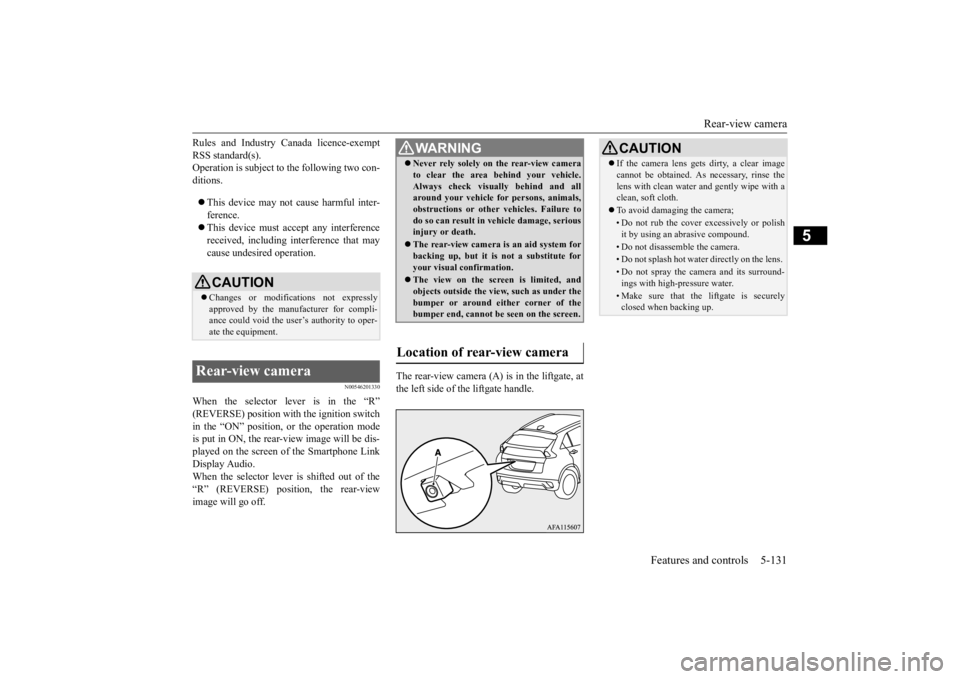
The rear-view camera (A) is in the liftgate, at the left side of the liftgate handle.
CAUTION Changes or modifications not expressly approved by the manufacturer for compli- ance could void the user’s authority to oper-ate the equipment.
Rear-view camera
WA R N I N G Never rely solely on the rear-view camera to clear the area behind your vehicle. Always check visually behind and all around your vehicle for persons, animals, obstructions or other vehicles. Failure todo so can result in vehicle damage, serious injury or death. The rear-view camera is an aid system for backing up, but it is not a substitute for your visual confirmation. The view on the screen is limited, and objects outside the view, such as under thebumper or around either corner of the bumper end, cannot be seen on the screen.
Location of rear-view camera
CAUTION If the camera lens gets dirty, a clear image cannot be obtained. As necessary, rinse the lens with clean water and gently wipe with a clean, soft cloth. To avoid damaging the camera;• Do not rub the cover excessively or polish it by using an abrasive compound. • Do not disassemble the camera.• Do not splash hot water directly on the lens. • Do not spray the camera and its surround- ings with high-pressure water.• Make sure that the liftgate is securelyclosed when backing up.
BK0277700US.book
131 ページ 2019年3月8日 金曜日 午前9時23分