steering wheel adjustment MITSUBISHI ECLIPSE CROSS 2020 Owner's Manual (in English)
[x] Cancel search | Manufacturer: MITSUBISHI, Model Year: 2020, Model line: ECLIPSE CROSS, Model: MITSUBISHI ECLIPSE CROSS 2020Pages: 427, PDF Size: 78.05 MB
Page 5 of 427
Instruments and controls 1-1
1
Overview
N00100202951
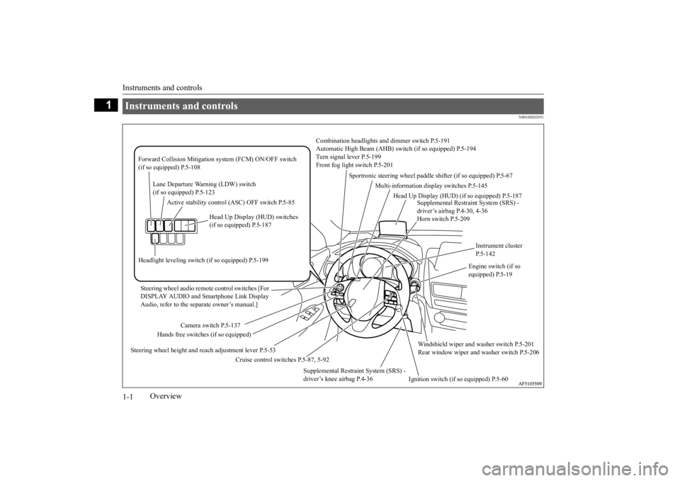
Instruments and controls
Combination headlights an
d dimmer switch P.5-191
Automatic High Beam (AHB) sw
itch (if so equipped) P.5-194
Turn signal lever P.5-199 Front fog light switch P.5-201
Steering wheel audio remote control switches [For DISPLAY AUDIO and Smartphone Link Display Audio, refer to the separate owner’s manual.]
Active stability control (ASC) OFF switch P.5-85
Supplemental Restraint System (SRS) - driver’s airbag P.4-30, 4-36Horn switch P.5-209
Instrument cluster P.5-142
Windshield wiper and washer switch P.5-201 Rear window wiper and
washer switch P.5-206
Cruise control switches P.5-87, 5-92
Steering wheel height and reach adjustment lever P.5-53
Engine switch (if so equipped) P.5-19
Sportronic steering wheel paddle
shifter (if so equipped) P.5-67
Lane Departure Warning (LDW) switch (if so equipped) P.5-123
Forward Collision Mitigation
system (FCM) ON/OFF switch
(if so equipped) P.5-108
Supplemental Restraint System (SRS) - driver’s knee airbag P.4-36
Ignition switch (if so equipped) P.5-60
Head Up Display (HUD) switches (if so equipped) P.5-187
Headlight leveling switch
(if so equipped) P.5-199
Camera switch P.5-137
Hands free switches (if so equipped)
Multi-information display switches P.5-145
Head Up Display (HUD)
(if so equipped) P.5-187
BK0277700US.bo
ok 1 ページ 2019年3月8日 金曜日 午前9時23分
Page 38 of 427
Seats and restraint systems
Seat and restraint systems 4-3
4
N00401601277
Your vehicle has seat belts and other safety features that help protect you and your pas-sengers in an accident. Seat belts are the most important safety device. When worn properly, seat belts canreduce the chance of serious injury or death in various types of crashes. For added protec- tion during a severe frontal collision, yourvehicle has a Supplemental Restraint System(SRS) with airbags for the driver and passen- gers. The seats, head restraints, and door locks also are safety equipment, which mustbe used correctly. Always check the following before you drive: That everyone in your vehicle is properly wearing their seat belt. That infants and small children are prop- erly secured in an appropriate child restraint system in the rear seat. That all doors are fully closed and locked. That seatbacks are upright, with head restraints properly adjusted.
Safety equipment cannot prevent injury or death in all motor vehicle accidents. How-ever, you can help reduce the risk of injury or death, by following the instructions in this manual.
N00401801484
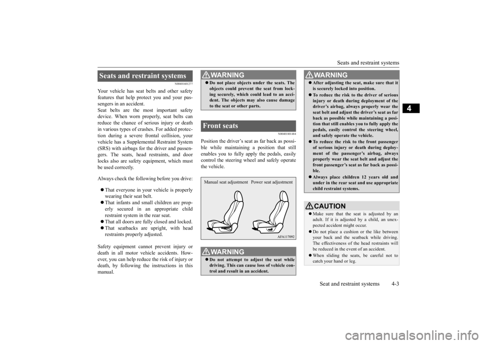
Position the driver’s seat
as far back as possi-
ble while maintaining a position that still enables you to fully apply the pedals, easily control the steering wheel and safely operatethe vehicle.
Seats and restraint systems
WA R N I N G Do not place objects under the seats. The objects could prevent the seat from lock- ing securely, which could lead to an acci- dent. The objects ma
y also cause damage
to the seat or other parts.
Front seats
WA R N I N G Do not attempt to adjust the seat while driving. This can cause loss of vehicle con- trol and result in an accident.Manual seat adjustment Power seat adjustment
After adjusting the seat, make sure that it is securely locked into position. To reduce the risk to the driver of serious injury or death during deployment of thedriver’s airbag, always properly wear the seat belt and adjust th
e driver’s seat as far
back as possible while maintaining a posi-tion that still enables
you to fully apply the
pedals, easily control the steering wheel, and safely operate the vehicle. To reduce the risk to the front passenger of serious injury or death during deploy-ment of the passenger’s airbag, always properly wear the seat belt and adjust the front passenger’s seat as far back as possi-ble. Always place children 12 years old and under in the rear seat and use appropriate child restraint systems.CAUTION Make sure that the seat is adjusted by an adult. If it is adjusted by a child, an unex-pected accident might occur. Do not place a cushion or the like between your back and the seatback while driving. The effectiveness of the head restraints willbe reduced in the event of an accident. When sliding the seats, be careful not to catch your hand or leg.WA R N I N G
BK0277700US.bo
ok 3 ページ 2019年3月8日 金曜日 午前9時23分
Page 134 of 427

Steering wheel height and reach adjustment
Features and controls 5-53
5
Warning light Warning display If there is a malfunction in the system, the warning light will come on. In addition, thewarning display appears on the information screen in the multi-information display.
Under normal conditions, the warning light only comes on when the ignition switch is turned to the “ON” position or the operation mode is put in ON and goes off a few secondslater.
N00511501241
To adjust the steering wheel to the desiredposition, move the lever upward or down-
If the acceleration of the vehicle seems abnormally slow after the vehicle has been parked with the Electric parking brake applied in cold weather, stop the vehicle in a safe place, then apply and release the Elec-tric parking brake. If the vehicle acceleration is still slow, contact the nearest authorized Mitsubishi Motors dealer or a repair facilityof your choice.NOTE
When the ignition switch or the operation mode is other than ON, the parking brake cannot be released. If the Electric parking brake does not auto- matically release, it may be released by man-ual operation. When the selector lever is other than “P” (PARK) position, if you try to release the Electric parking brake without depressing the brake pedal, the warning display willappear.CAUTION
If you start driving without releasing the Electric parking brake, the warning display will appear. If the driver’s foot contacts the accelerator pedal in the condition that the Electric park-ing brake can release by an automatic opera- tion, the Electric parking brake may be released automatically.
Warning light/display
NOTE
CAUTION When the Electric parking brake warning light does not illuminate or remains illumi- nated when the ignition switch is turned tothe “ON” position or the operation mode is put in ON, or comes on while driving, the Electric parking brake may not be applied orreleased. Immediately contact the nearest authorized Mitsubishi Motors dealer or a repair facilityof your choice. For details, refer to “Electric parking brake warning light” on page 5-184. When parking your vehicle while the Elec-tric parking brake warning light is illumi- nated, park the vehicle on level and stable ground, move the selector lever to the “P”(PARK) position and place chocks, blocks, stones behind and in front of the tires to pre- vent the vehicle from moving.
Steering wheel height and reach adjustment
BK0277700US.bo
ok 53 ページ 2019年3月8日 金曜日 午前9時23分
Page 210 of 427
Tire pressure monitoring system (TPMS)
Features and controls 5-129
5
allow the TPMS to continue to function prop- erly.
N00532801579
1. If the tire pressure monitoring system warning light illuminates, avoiding hard braking, sharp steering maneuvers andhigh speeds. You should stop and adjustthe tires to the proper inflation pressure as soon as possible. Adjust the spare tire at the same time. Refer to “Tires” on page9-12.
2. If the tire pressure monitoring system warning light remains illuminated after you have been driving for approximately20 minutes after you adjust the tire infla- tion pressure, one or more of the tires may have a puncture. Inspect the tire and if ithas a puncture, have it repaired by anauthorized Mitsubishi Motors dealer as soon as possible.
The tire pressure monitoring system may not work normally in the following circum-stances: A wireless facility or device using the same frequency is near the vehicle. Snow or ice is stuck inside the fenders and/or on the wheels. The tire inflation pressure sensor’s battery is dead. Wheels other than Mitsubishi genuine wheels are being used. Wheels that are not fitted with tire infla- tion pressure sensors are being used. Wheels whose ID co
des are not memo-
rized by the vehicle are used. Compact spare tire is fitted as a road wheel.
If the warning light / display illuminates while driving
NOTE
In addition, the warning display is displayed on the information screen in the multi-infor- mation display. When inspecting or adjusting the tire pres- sure, do not apply excessive force to thevalve stem to avoid breakage. After inspecting or adjusting the tire pres- sure, always reinstall the valve cap on the valve stem. Without the valve cap, dirt or moisture could get into the valve, resulting in damage to the tire inflation pressure sensor. Do not use metal valve caps, which may cause a metal reaction, resulting in corrosionand damage of the tire inflation pressure sen- sors.
Once adjustments have been made, the warn- ing light will go off after a few minutes of driving.WA R N I N G If the warning light / display illuminates while you are driving, avoid hard braking,sharp steering maneuvers and high speeds. Driving with an under-inflated tireadversely affects vehicle performance and can result in an accident.CAUTION If a tire has a puncture, replace that tire with the spare tire. Driving on a punctured tire could lead to an accident. The warning light / display may not illumi- nate immediately in the event of a tire blow-out or rapid leak.NOTE
NOTE
To avoid the risk of damage to the tire infla- tion pressure sensors, have any punctured tire repaired by an authorized Mitsubishi Motors dealer. If the tire repair is not done by an authorized Mitsubishi Motors dealer, it isnot covered by your warranty. Do not use an aerosol puncture-repair spray on any tire. Such a spray could damage the tire inflation pressure sensors.Have any puncture repaired by an authorized Mitsubishi Motors dealer.
BK0277700US.book
129 ページ 2019年3月8日 金曜日 午前9時23分
Page 281 of 427
Hazard warning flasher switch 5-200 Features and controls
5
tion (1). It will return to the neutral position when you let go. Use the full position (2) when making a normal turn. The lever will return to the neutral position when the turn iscomplete. There may be times when the lever does not return to the neutral position. This usually happens when the steering wheel isturned only slightly. You can easily return the lever by hand. Also, when you move the lever to (1) slightlythen release it, the turn signal lights and theindicator light in the instrument cluster will flash three times.
N00522701344
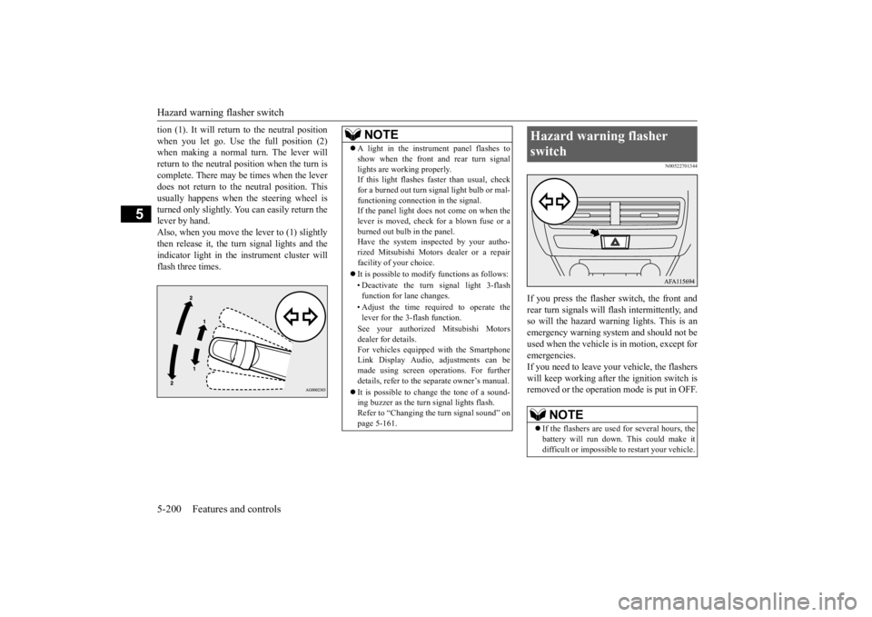
If you press the flasher switch, the front and rear turn signals will flash intermittently, and so will the hazard warn
ing lights. This is an
emergency warning system and should not beused when the vehicle is in motion, except foremergencies. If you need to leave your vehicle, the flashers will keep working after the ignition switch isremoved or the operation mode is put in OFF.
NOTE
A light in the instrument panel flashes to show when the front and rear turn signal lights are working properly. If this light flashes faster than usual, check for a burned out turn signal light bulb or mal-functioning connection in the signal. If the panel light does not come on when the lever is moved, check for a blown fuse or aburned out bulb in the panel. Have the system inspected by your autho- rized Mitsubishi Motors dealer or a repairfacility of your choice. It is possible to modify functions as follows: • Deactivate the turn signal light 3-flash function for lane changes. • Adjust the time required to operate the lever for the 3-flash function. See your authorized Mitsubishi Motors dealer for details.For vehicles equipped with the Smartphone Link Display Audio, adjustments can be made using screen operations. For furtherdetails, refer to the separate owner’s manual. It is possible to change the tone of a sound- ing buzzer as the turn signal lights flash. Refer to “Changing the turn signal sound” on page 5-161.
Hazard warning flasher switch
NOTE
If the flashers are used for several hours, the battery will run down. This could make it difficult or impossible to restart your vehicle.
BK0277700US.book
200 ページ 2019年3月8日 金曜日 午前9時23分
Page 289 of 427
Heated steering wheel switch (if so equipped) 5-208 Features and controls
5
N00589100045
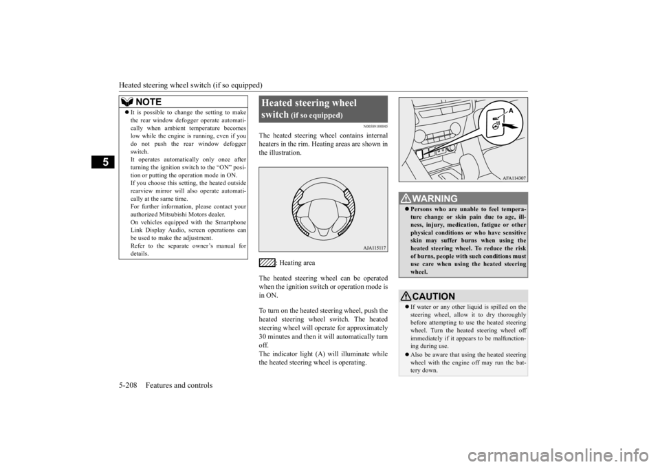
The heated steering wheel contains internal heaters in the rim. Heating areas are shown inthe illustration.
: Heating area
The heated steering wheel can be operated when the ignition switch or operation mode is in ON. To turn on the heated steering wheel, push the heated steering wheel switch. The heatedsteering wheel will operate for approximately 30 minutes and then it will automatically turn off.The indicator light (A) will illuminate while the heated steering wheel is operating.
It is possible to change the setting to make the rear window defogger operate automati- cally when ambient temperature becomes low while the engine is running, even if you do not push the rear window defoggerswitch. It operates automatically only once after turning the ignition switch to the “ON” posi-tion or putting the operation mode in ON. If you choose this setting, the heated outside rearview mirror will also operate automati-cally at the same time. For further information, please contact your authorized Mitsubishi Motors dealer.On vehicles equipped with the Smartphone Link Display Audio, screen operations can be used to make the adjustment.Refer to the separate owner’s manual for details.NOTE
Heated steering wheel switch
(if so equipped)
WA R N I N G Persons who are unable to feel tempera- ture change or skin pain due to age, ill- ness, injury, medication, fatigue or other physical conditions or who have sensitiveskin may suffer burns when using the heated steering wheel. To reduce the risk of burns, people with such conditions mustuse care when using the heated steering wheel.CAUTION If water or any other li
quid is spilled on the
steering wheel, allow it to dry thoroughly before attempting to use the heated steering wheel. Turn the heated steering wheel offimmediately if it appears to be malfunction- ing during use. Also be aware that using the heated steering wheel with the engine off may run the bat- tery down.
BK0277700US.book
208 ページ 2019年3月8日 金曜日 午前9時23分
Page 323 of 427
Trailer towing 6-14 Driving safety
6
Towing a trailer requires a certain amount of experience. Before setting out for the open road, you’llwant to get to know your trailer. Acquaint
yourself with the feel
of handling and braking
with the added weight of the trailer. Always keep in mind that the vehicle you are driving is now a good deal longer and not nearly asresponsive as your vehicle is without a trailer. Before you start, check the trailer hitch, safety chains, tires and mirror adjustment. Be sure your vehicle’s tires are inflated to the cold inflation pressure listed in the manual.You’ll find these numbers on the tire and loading information placard at the sill of the driver’s door.Refer to “Tire inflation pressures” on page 9-15. Stay at least twice as far behind the vehicle ahead as you would when driving your vehi-cle without a trailer. This can help you avoid situations that require heavy braking and sud- den turns.
You’ll need more passing distance up ahead when you’re towing a trailer. And, becauseyou’re a good deal longer, you’ll need to go much farther beyond the passed vehicle before you can return to your lane. Hold the bottom of the steering wheel with one hand. Then, to move the trailer to the left, just move that hand to the left. To move thetrailer to the right, move your hand to the right. Always back up slowly and, if possible, have someone guide you. When you’re turning with a trailer, make wider than normal turns to help prevent thetrailer from striking shoulders, curbs, road signs, trees or other objects.
Operating hints
WA R N I N G If you have a rear window open and you tow a trailer with your vehicle, carbon monoxide gas which you cannot see or smell could come into your vehicle. It cancause unconsciousness or death. Refer to “Exhaust system” on page 9-22. To maximize your safety when towing atrailer:• Have your exhaust system inspected forleaks, and make necessary repairs before starting on your trip.• Keep the rear windows closed.• If exhaust does come into your vehicle through a window or another opening, drive with your front, main heating or cooling system on and with the blower onany speed. This will bring fresh, outside air into your vehicle. Do not use recircu- lation because it only recirculates the airinside your vehicle. Refer to “Air selec- tion switch” on page 7-9.
Driver preparation
Vehicle preparation Tire Following distance
Passing Backing up Making turns
CAUTION Making sharp turns while towing a trailer could cause the trailer to come in contact with the vehicle. Your vehicle could be dam- aged. Avoid making sharp turns while tow-ing a trailer.
BK0277700US.bo
ok 14 ページ 2019年3月8日 金曜日 午前9時23分
Page 423 of 427

Alphabetical index 12-4
12
Overheating
......................
...................
8-4
P
Parking
.........................
.......................
6-6
Parking brake
................
.................
5-49
Parking brake lever stroke
...................
9-19
Parking lights
Bulb location and capacity
...............
9-28
Replacement
.................
.................
9-30
Polishing
.......................
.....................
9-38
Power brakes
.....................
.................
5-76
Power outlet
..................
...................
5-211
Power panoramic sunroof
....................
5-46
Power windows
.................
.................
5-43
Puncture (Tire changing)
.......................
8-6
R
Radiator cap
......................
...................
9-8
Radio
General information about your radio 7-23
Reading lights
Bulb location and capacity
...............
9-29
Rear axle oil
...............
.................
9-9
, 11-7
Rear combination lights
Bulb location and capacity
...............
9-28
Replacement
.................
.................
9-32
Rear Cross Traffic Alert
....................
5-119
Rear seat adjustment
.............................
4-6
Rear side-marker lights
Bulb location and capacity
...............
9-28
Rear turn signal light
Bulb location and capacity
...............
9-28
Replacement
...................
................
9-32
Rear-view camera
.............................
5-131
Rearview mirror
Inside rearview mirror
.....................
5-54
Outside rearview mirrors
.................
5-56
Replacement of light bulbs
...................
9-27
Replacing tires and wheels
...................
9-16
Reporting Safety Defects
.....................
10-2
S
Safe driving techniques
.........................
6-4
S-AWC (Super-All Wheel Control)
......
5-70
Seat belt
......................
.......................
4-13
Adjustable seat belt shoulder anchor
.4-19
Child restraint systems
.....................
4-22
Front passenger seat belt warning light
.....
4-19 Maintenance and inspection
.............
4-30
Seat belt extender
............................
4-20
Seat belt force limiter
......................
4-22
Seat belt pre-tensioners
....................
4-21
Seat belt use during pregnancy
.........
4-21
Seats
...........................
........................
4-2
Arm rest
..................
..................
4-6
, 4-8
Front seats
....................
...................
4-3
Head restraints
.................
................
4-9
Making a cargo area
........................
4-12
Rear seats
.....................
...................
4-6
Seats and restraint systems
................
4-3
Service brake
.....................
.................
5-76
Service precautions
...............
................
9-2
Side turn signal light
Bulb location and capacity
...............
9-28
Snow tires
.....................
.....................
9-18
Spark plugs
...................
.....................
9-20
Starting the engine
.....................
5-25
, 5-61
Steering
Steering wheel height and reach adjustment5-53
Stop lights
Bulb location and capacity
...............
9-28
Storage spaces
...................
...............
5-221
Sun visors
.....................
...................
5-210
Super-all wheel control (S-AWC)
S-AWC drive mode display
.............
5-71
S-AWC drive mode-selector
............
5-71
S-AWC operation display
................
5-72
Supplemental Restraint System
............
4-30
How the Supplemental Restraint System works
.....................
.....................
4-33
Maintenance service
.......................
4-44
BK0277700US.bo
ok 4 ページ 2019年3月8日 金曜日 午前9時23分