center console MITSUBISHI ENDEAVOR 2004 Service Repair Manual
[x] Cancel search | Manufacturer: MITSUBISHI, Model Year: 2004, Model line: ENDEAVOR, Model: MITSUBISHI ENDEAVOR 2004Pages: 3870, PDF Size: 98.47 MB
Page 283 of 3870
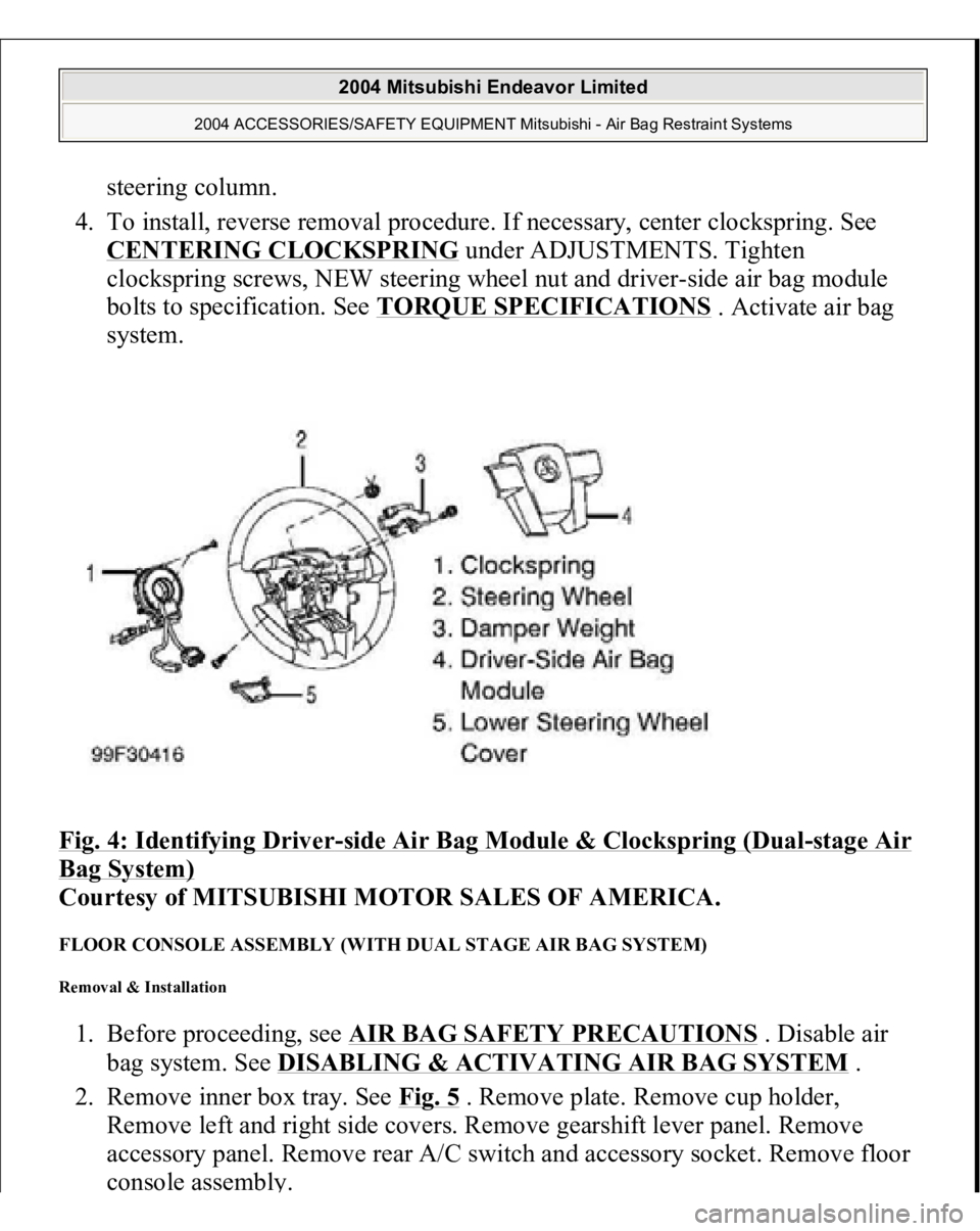
steering column.
4. To install, reverse removal procedure. If necessary, center clockspring. See
CENTERING CLOCKSPRING
under ADJUSTMENTS. Tighten
clockspring screws, NEW steering wheel nut and driver-side air bag module
bolts to specification. See TORQUE SPECIFICATIONS
. Activate air bag
system.
Fig. 4: Identifying Driver
-side Air Bag Module & Clockspring (Dual
-stage Air
Bag System)
Courtesy of MITSUBISHI MOTOR SALES OF AMERICA.
FLOOR CONSOLE ASSEMBLY (WITH DUAL STAGE AIR BAG SYSTEM) Removal & Installation 1. Before proceeding, see AIR BAG SAFETY PRECAUTIONS
. Disable air
bag system. See DISABLING & ACTIVATING AIR BAG SYSTEM
.
2. Remove inner box tray. See Fig. 5
. Remove plate. Remove cup holder,
Remove left and right side covers. Remove gearshift lever panel. Remove
accessory panel. Remove rear A/C switch and accessory socket. Remove floor
console assembl
y.
2004 Mitsubishi Endeavor Limited
2004 ACCESSORIES/SAFETY EQUIPMENT Mitsubishi - Air Bag Restraint Systems
Page 287 of 3870
CONSOLE ASSEMBL
Y . Remove left and right A-pillar trim panels.
Remove hood lock release handle.
3. Remove end panel. See Fig. 8
. Remove driver-side knee bolster. Remove fog
light switch. Remove steering column upper and lower covers. Remove
combination meter assembly. Remove center panel assembly. Remove air
vents. Remove radio panel. Remove AC-heater control assembly.
4. Remove hazard warning switch. Remove console meter hood. Remove multi-
center display unit. Remove audio components. Remove glove box assembly.
Remove left and right speaker covers. Remove speakers. Disconnect
clockspring and steering column switch connectors. Remove photo sensor and
photo sensor clamp.
5. Remove interior temperature sensor. Disconnect passenger-side air bag module
connector. Remove left and right center instrument panel brackets. Disconnect
remaining electrical connectors. Remove instrument panel nuts and bolts.
Remove instrument panel.
6. To install, reverse removal procedure. Tighten NEW steering wheel nut and
drive
r-side air ba
g module bolts to s
pecification. Activate air ba
g system.
2004 Mitsubishi Endeavor Limited
2004 ACCESSORIES/SAFETY EQUIPMENT Mitsubishi - Air Bag Restraint Systems
Page 296 of 3870
Removal & Installation (Single Stage AIR Bag System
)
1. Before proceeding, see AIR BAG SAFETY PRECAUTIONS
. Turn ignition
off. Disable air bag system. See DISABLING & ACTIVATING AIR BAG
SYSTEM
.
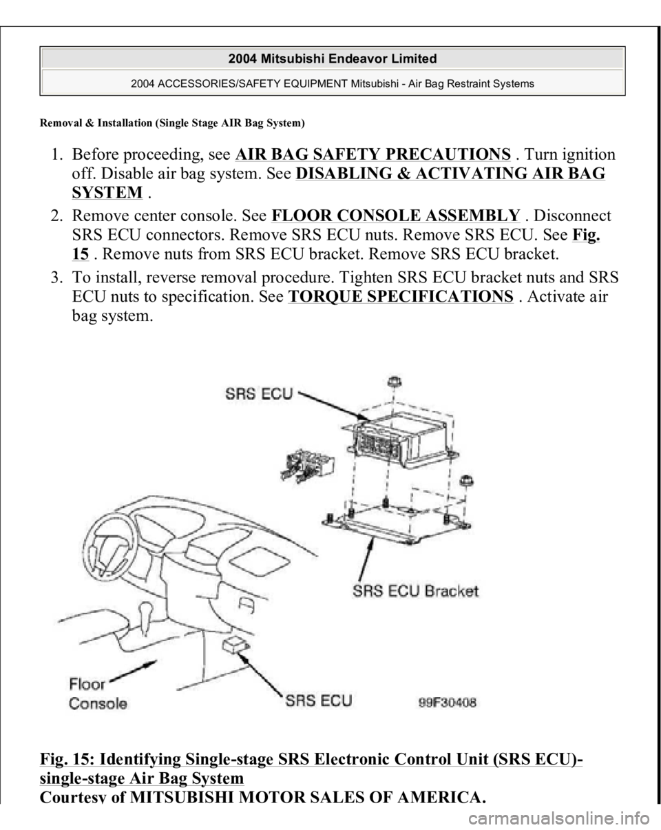
2. Remove center console. See FLOOR CONSOLE ASSEMBLY
. Disconnect
SRS ECU connectors. Remove SRS ECU nuts. Remove SRS ECU. See Fig.
15 . Remove nuts from SRS ECU bracket. Remove SRS ECU bracket.
3. To install, reverse removal procedure. Tighten SRS ECU bracket nuts and SRS
ECU nuts to specification. See TORQUE SPECIFICATIONS
. Activate air
bag system.
Fig. 15: Identifying Single
-stage SRS Electronic Control Unit (SRS ECU)
-
single
-stage Air Bag System
Courtes
y of MITSUBISHI MOTOR SALES OF AMERICA
.
2004 Mitsubishi Endeavor Limited
2004 ACCESSORIES/SAFETY EQUIPMENT Mitsubishi - Air Bag Restraint Systems
Page 297 of 3870
Removal & Installation (Dual-stage AIR Bag System)1. Before proceeding, see AIR BAG SAFETY PRECAUTIONS
. Turn ignition
off. Disable air bag system. See DISABLING & ACTIVATING AIR BAG
SYSTEM
.
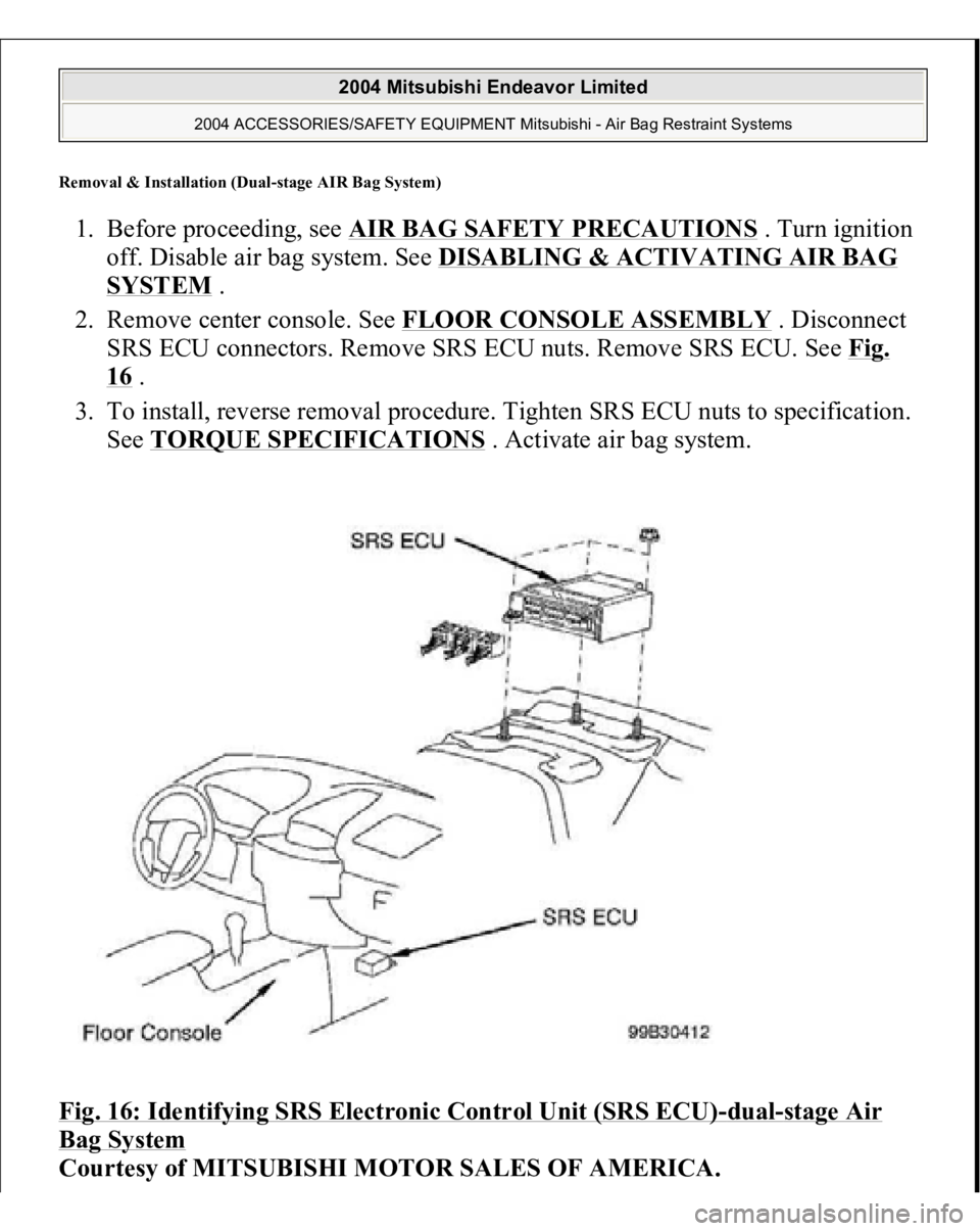
2. Remove center console. See FLOOR CONSOLE ASSEMBLY
. Disconnect
SRS ECU connectors. Remove SRS ECU nuts. Remove SRS ECU. See Fig.
16 .
3. To install, reverse removal procedure. Tighten SRS ECU nuts to specification.
See TORQUE SPECIFICATIONS
. Activate air bag system.
Fig. 16: Identifying SRS Electronic Control Unit (SRS ECU)
-dual
-stage Air
Bag System
Courtesy of MITSUBISHI MOTOR SALES OF AMERICA.
2004 Mitsubishi Endeavor Limited
2004 ACCESSORIES/SAFETY EQUIPMENT Mitsubishi - Air Bag Restraint Systems
Page 1095 of 3870

MOTORS MOTORS LOCATION SENDING UNITS & SENSORS SENDING UNITS & SENSORS LOCATION
4 .
Power Window Main Switch CPU
Integral to power window main switch.
See Fig. 15
.
SRS ECU
Under front of center console.Fig. 14
.
Sunroof ECU
At front of sunroof opening.Fig. 13
.
Component
Location
Door Lock Actuator (Left Front) (E-
20)
Rear of left front door.Fig. 77
.
Door Lock Actuator (Left Rear) (E-13)
Rear of left rear door.Fig. 77
.
Door Lock Actuator (Right Front) (E-
03)
Rear of right front door.Fig. 77
.
Door Lock Actuator (Right Rear) (E-
07)
Rear of right rear door.Fig. 77
.
Fuel Pump Module
In top of fuel tank.Fig. 64
.
Liftgate Actuator (F-11)
Lower center of liftgate. See Fig. 88
.
Power Steering Oil Pump
Lower right side of engine
compartment. See Fig. 36
.
Rear Blower Motor (C-20)
Rear of center console.Fig. 76
.
Rear Washer Motor (A-26)
In washer tank assembly.Fig. 79
.
Sunroof Motor Assembly
Right front of roof. See Fig. 62
.
Windshield Washer Motor (A-27)
In washer tank assembly.Fig. 79
.
Windshield Wiper Motor (A-03)
On left side of firewall.Fig. 79
.
Component
Location
ABS G Sensor Or G & Yaw Rate
Sensor
Under center console. See Fig. 67
.
Acceleration Pedal Position
Above accelerator pedal.Fig. 59
.
2004 Mitsubishi Endeavor LS
2004 MITSUBISHI Endeavor
Page 1099 of 3870
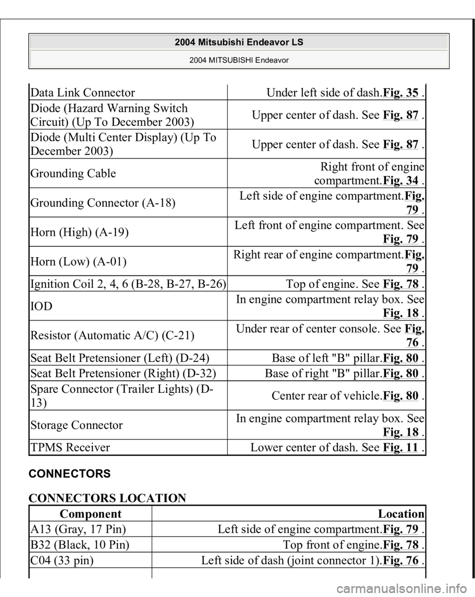
CONNECTORS CONNECTORS LOCATION Data Link Connector
Under left side of dash.Fig. 35
.
Diode (Hazard Warning Switch
Circuit) (Up To December 2003)
Upper center of dash. See Fig. 87
.
Diode (Multi Center Display) (Up To
December 2003)
Upper center of dash. See Fig. 87
.
Grounding Cable
Right front of engine
compartment.Fig. 34
.
Grounding Connector (A-18)
Left side of engine compartment.Fig.
79 .
Horn (High) (A-19)
Left front of engine compartment. See
Fig. 79
.
Horn (Low) (A-01)
Right rear of engine compartment.Fi
g.
79 .
Ignition Coil 2, 4, 6 (B-28, B-27, B-26)
Top of engine. See Fig. 78
.
IOD
In engine compartment relay box. See
Fig. 18
.
Resistor (Automatic A/C) (C-21)
Under rear of center console. See Fi
g.
76 .
Seat Belt Pretensioner (Left) (D-24)
Base of left "B" pillar.Fig. 80
.
Seat Belt Pretensioner (Right) (D-32)
Base of right "B" pillar.Fig. 80
.
Spare Connector (Trailer Lights) (D-
13)
Center rear of vehicle.Fig. 80
.
Storage Connector
In engine compartment relay box. See
Fig. 18
.
TPMS Receiver
Lower center of dash. See Fig. 11
.
Component
Location
A13 (Gray, 17 Pin)
Left side of engine compartment.Fig. 79
.
B32 (Black, 10 Pin)
Top front of engine.Fig. 78
.
C04 (33 pin)
Left side of dash (joint connector 1).Fig. 76
.
2004 Mitsubishi Endeavor LS
2004 MITSUBISHI Endeavor
Page 1100 of 3870
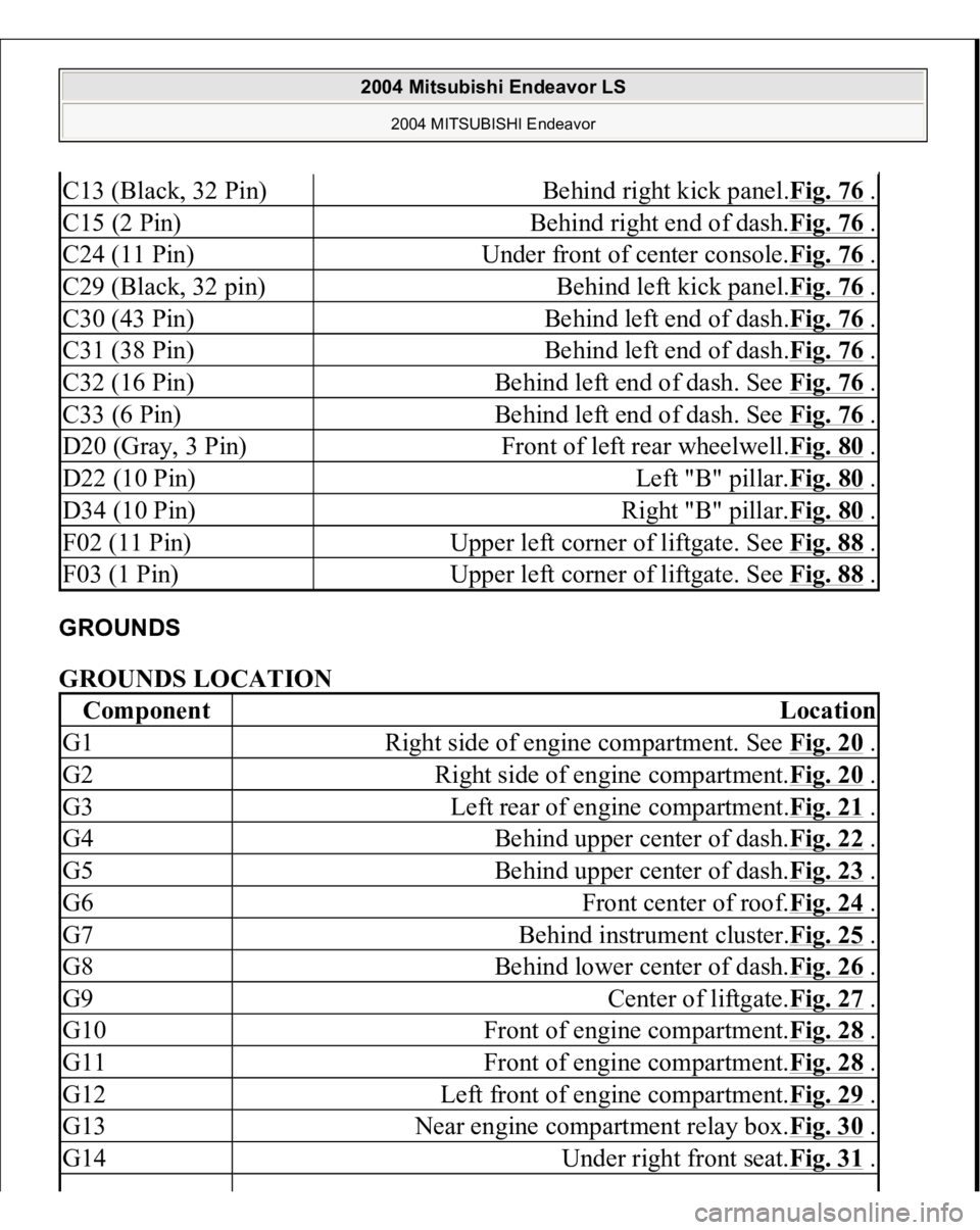
GROUNDS GROUNDS LOCATION C13 (Black, 32 Pin)
Behind right kick panel.Fig. 76
.
C15 (2 Pin)
Behind right end of dash.Fig. 76
.
C24 (11 Pin)
Under front of center console.Fig. 76
.
C29 (Black, 32 pin)
Behind left kick panel.Fig. 76
.
C30 (43 Pin)
Behind left end of dash.Fig. 76
.
C31 (38 Pin)
Behind left end of dash.Fig. 76
.
C32 (16 Pin)
Behind left end of dash. See Fig. 76
.
C33 (6 Pin)
Behind left end of dash. See Fig. 76
.
D20 (Gray, 3 Pin)
Front of left rear wheelwell.Fig. 80
.
D22 (10 Pin)
Left "B" pillar.Fig. 80
.
D34 (10 Pin)
Right "B" pillar.Fig. 80
.
F02 (11 Pin)
Upper left corner of liftgate. See Fig. 88
.
F03 (1 Pin)
Upper left corner of liftgate. See Fig. 88
.
Component
Location
G1
Right side of engine compartment. See Fig. 20
.
G2
Right side of engine compartment.Fig. 20
.
G3
Left rear of engine compartment.Fig. 21
.
G4
Behind upper center of dash.Fig. 22
.
G5
Behind upper center of dash.Fig. 23
.
G6
Front center of roof.Fig. 24
.
G7
Behind instrument cluster.Fig. 25
.
G8
Behind lower center of dash.Fig. 26
.
G9
Center of liftgate.Fig. 27
.
G10
Front of engine compartment.Fig. 28
.
G11
Front of engine compartment.Fig. 28
.
G12
Left front of engine compartment.Fig. 29
.
G13
Near engine compartment relay box.Fig. 30
.
G14
Under right front seat.Fig. 31
.
2004 Mitsubishi Endeavor LS
2004 MITSUBISHI Endeavor
Page 1107 of 3870
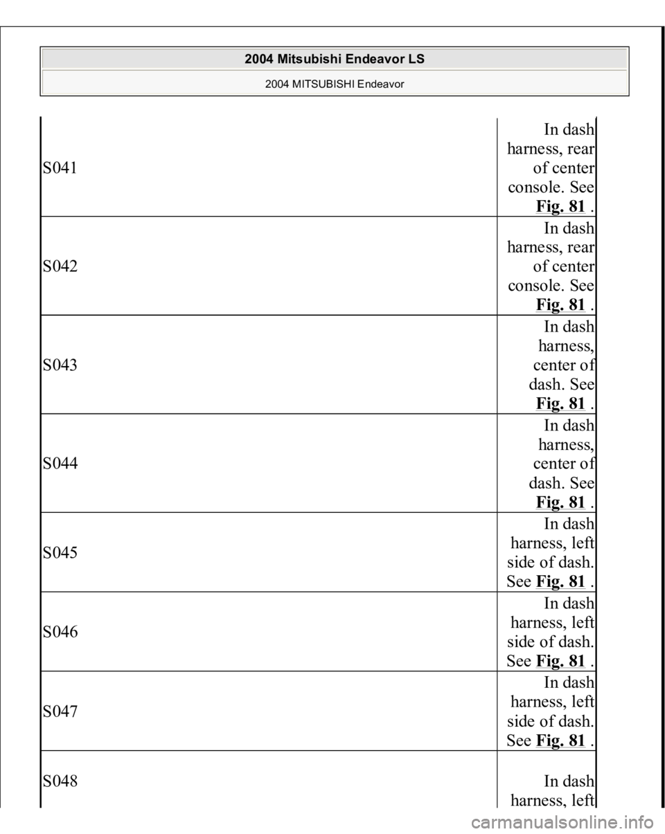
S041
In dash
harness, rear
of center
console. See
Fig. 81
.
S042
In dash
harness, rear
of center
console. See
Fig. 81
.
S043
In dash
harness,
center o
f
dash. See
Fig. 81 .
S044
In dash
harness,
center o
f
dash. See
Fig. 81 .
S045
In dash
harness, left
side of dash.
See Fig. 81
.
S046
In dash
harness, left
side of dash.
See Fig. 81
.
S047
In dash
harness, left
side of dash.
See Fig. 81
.
S048
In dash
harness
, left
2004 Mitsubishi Endeavor LS
2004 MITSUBISHI Endeavor
Page 3112 of 3870
A whining sound is caused by the TCL/ASC hydraulic unit motor. When pressure is applied to the brake pedal, the pulsation of the pedal causes a
scraping sound. When the brakes are applied firmly, the TCL/ASC operates, rapidly applying
and releasing the brakes many times per second. This repeated application and
release of braking forces can cause the suspension to make a thumping sound
and the tires to squeak.
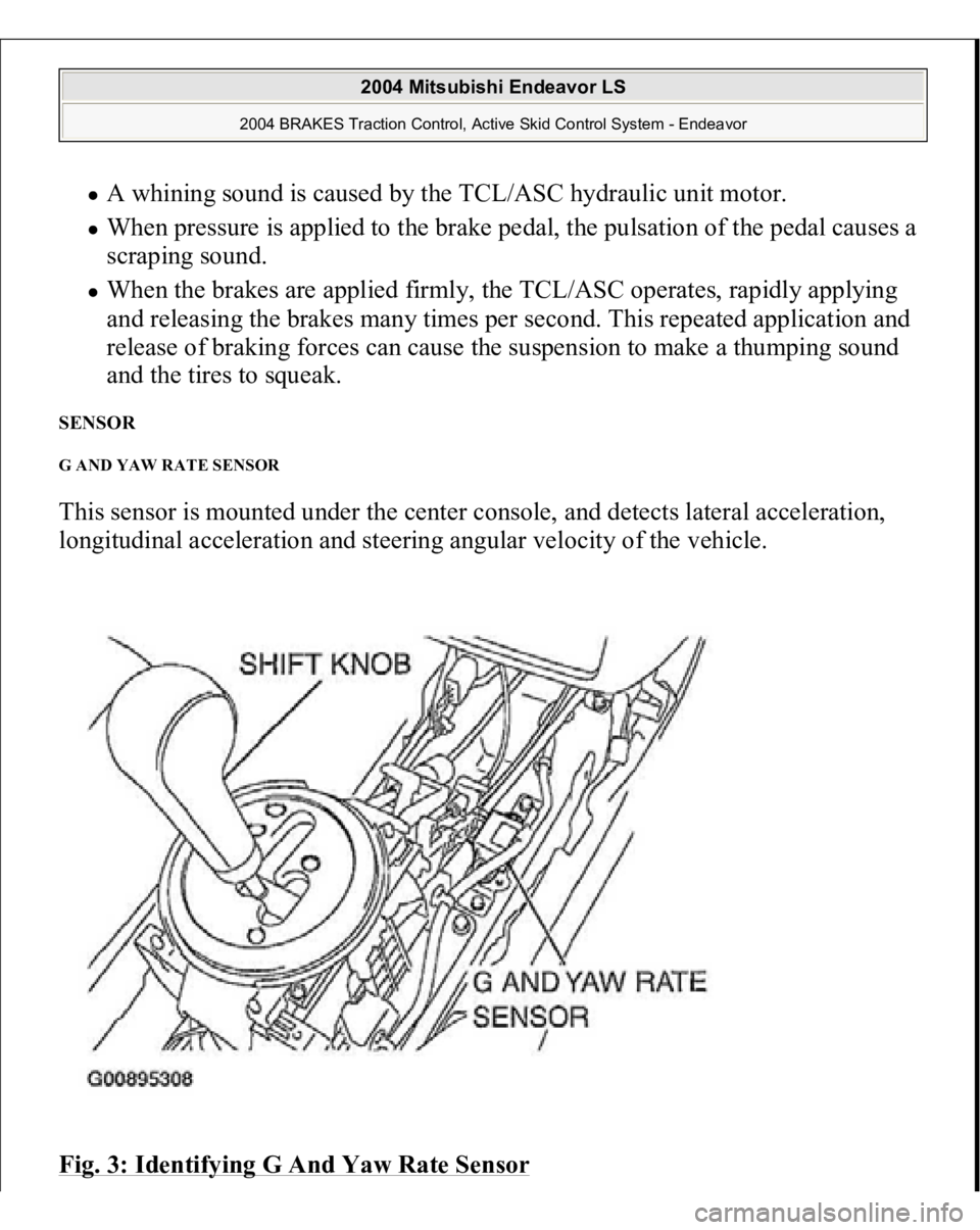
SENSOR G AND YAW RATE SENSOR This sensor is mounted under the center console, and detects lateral acceleration,
longitudinal acceleration and steering angular velocity of the vehicle.
Fig. 3: Identifying G And Yaw Rate Sensor
2004 Mitsubishi Endeavor LS
2004 BRAKES Traction Control, Active Skid Control System - Endeavor