instrument panel MITSUBISHI ENDEAVOR 2004 Service Repair Manual
[x] Cancel search | Manufacturer: MITSUBISHI, Model Year: 2004, Model line: ENDEAVOR, Model: MITSUBISHI ENDEAVOR 2004Pages: 3870, PDF Size: 98.47 MB
Page 286 of 3870
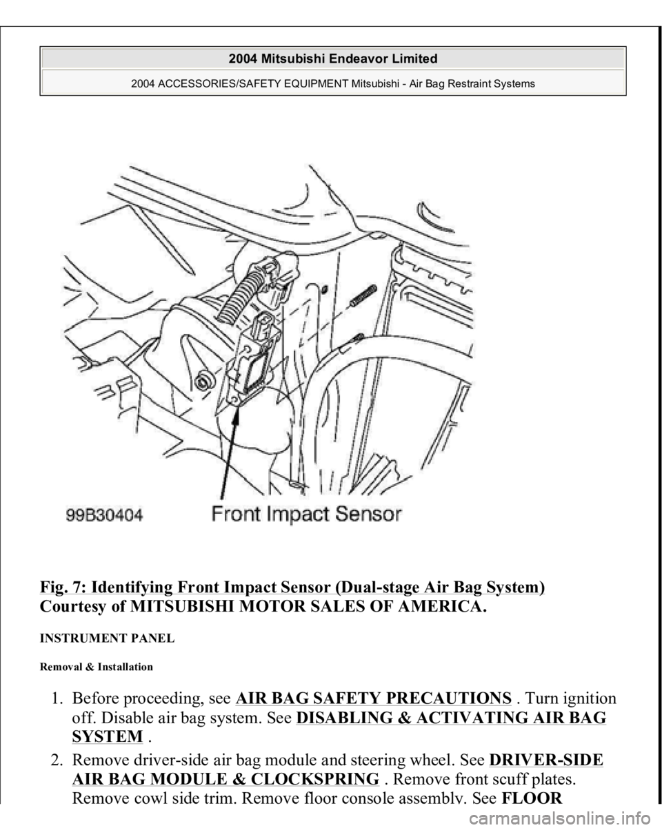
Fig. 7: Identifying Front Impact Sensor (Dual
-stage Air Bag System)
Courtesy of MITSUBISHI MOTOR SALES OF AMERICA.
INSTRUMENT PANEL Removal & Installation 1. Before proceeding, see AIR BAG SAFETY PRECAUTIONS
. Turn ignition
off. Disable air bag system. See DISABLING & ACTIVATING AIR BAG
SYSTEM
.
2. Remove driver-side air bag module and steering wheel. See DRIVER
-SIDE
AIR BAG MODULE & CLOCKSPRING
. Remove front scuff plates.
Remove cowl side trim. Remove floor console assembl
y. See FLOOR
2004 Mitsubishi Endeavor Limited
2004 ACCESSORIES/SAFETY EQUIPMENT Mitsubishi - Air Bag Restraint Systems
Page 287 of 3870
CONSOLE ASSEMBL
Y . Remove left and right A-pillar trim panels.
Remove hood lock release handle.
3. Remove end panel. See Fig. 8
. Remove driver-side knee bolster. Remove fog
light switch. Remove steering column upper and lower covers. Remove
combination meter assembly. Remove center panel assembly. Remove air
vents. Remove radio panel. Remove AC-heater control assembly.
4. Remove hazard warning switch. Remove console meter hood. Remove multi-
center display unit. Remove audio components. Remove glove box assembly.
Remove left and right speaker covers. Remove speakers. Disconnect
clockspring and steering column switch connectors. Remove photo sensor and
photo sensor clamp.
5. Remove interior temperature sensor. Disconnect passenger-side air bag module
connector. Remove left and right center instrument panel brackets. Disconnect
remaining electrical connectors. Remove instrument panel nuts and bolts.
Remove instrument panel.
6. To install, reverse removal procedure. Tighten NEW steering wheel nut and
drive
r-side air ba
g module bolts to s
pecification. Activate air ba
g system.
2004 Mitsubishi Endeavor Limited
2004 ACCESSORIES/SAFETY EQUIPMENT Mitsubishi - Air Bag Restraint Systems
Page 288 of 3870
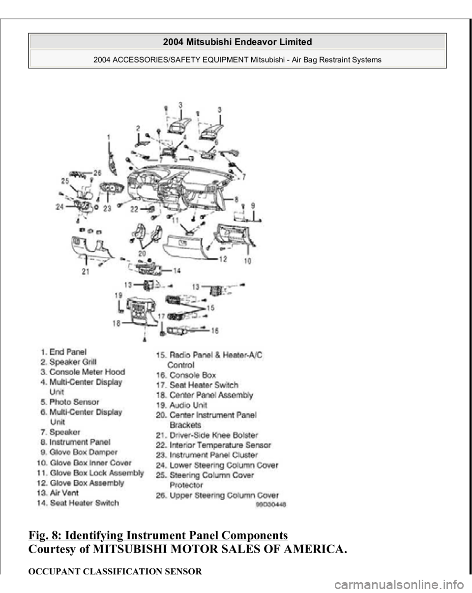
Fig. 8: Identifying Instrument Panel Components
Courtesy of MITSUBISHI MOTOR SALES OF AMERICA.
OCCUPANT CLASSIFICATION SENSOR
2004 Mitsubishi Endeavor Limited
2004 ACCESSORIES/SAFETY EQUIPMENT Mitsubishi - Air Bag Restraint Systems
Page 289 of 3870
Removal & Installation 1. Before proceeding, see AIR BAG SAFETY PRECAUTIONS
. Disable air
bag system. See DISABLING & ACTIVATING AIR BAG SYSTEM
.
Remove passenger-side front seat assembly.
2. To install, reverse removal procedure. Perform occupant classification
calibration procedure. See OCCUPANT CLASSIFICATION SENSOR
under REMOVAL & INSTALLATION. Tighten front seat nuts and bolts to
specification. See TORQUE SPECIFICATIONS
. Activate air bag system.
PASSENGER-SIDE AIR BAG MODULE Removal & Installation (Single Stage AIR Bag System) 1. Before proceeding, see AIR BAG SAFETY PRECAUTIONS
. Turn ignition
off. Disable air bag system. See DISABLING & ACTIVATING AIR BAG
SYSTEM
.
2. Remove instrument panel. See INSTRUMENT PANEL
. Remove passenger-
side air bag module bracket. See Fig. 9
. Remove passenger-side air bag
module.
3. To install, reverse removal
procedure. Activate ai
r ba
g system.
2004 Mitsubishi Endeavor Limited
2004 ACCESSORIES/SAFETY EQUIPMENT Mitsubishi - Air Bag Restraint Systems
Page 290 of 3870
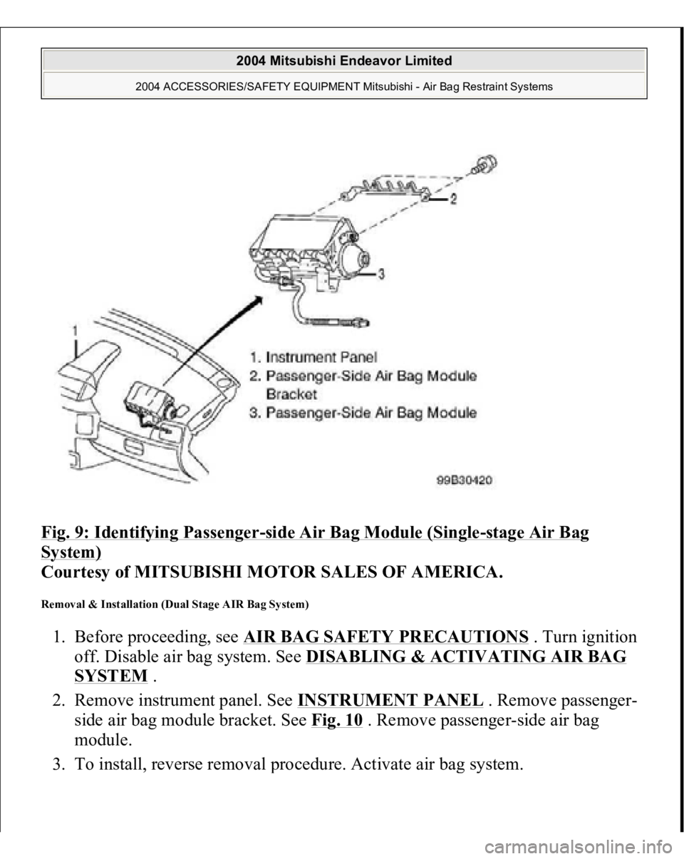
Fig. 9: Identifying Passenger
-side Air Bag Module (Single
-stage Air Bag
System)
Courtesy of MITSUBISHI MOTOR SALES OF AMERICA.
Removal & Installation (Dual Stage AIR Bag System) 1. Before proceeding, see AIR BAG SAFETY PRECAUTIONS
. Turn ignition
off. Disable air bag system. See DISABLING & ACTIVATING AIR BAG
SYSTEM
.
2. Remove instrument panel. See INSTRUMENT PANEL
. Remove passenger-
side air bag module bracket. See Fig. 10
. Remove passenger-side air bag
module.
3. To install, reverse removal
procedure. Activate ai
r ba
g system.
2004 Mitsubishi Endeavor Limited
2004 ACCESSORIES/SAFETY EQUIPMENT Mitsubishi - Air Bag Restraint Systems
Page 300 of 3870
1. Turn ignition on. If AIR BAG warning light comes on for 7 seconds and then
goes off, SRS is functioning properly. If AIR BAG warning light does not
function as described, turn ignition off. If AIR BAG warning light malfunction
or scan tool communication problems are encountered, diagnose malfunction
using appropriate table. SeeSCAN TOOL COMMUNICATION
SYMPTOMS (SINGLE
-STAGE AIR BAG SYSTEMS)
and SCAN TOOL
COMMUNICATION SYMPTOMS (DUAL
-STAGE AIR BAG
SYSTEMS)
tables.
2. Utilizing a laptop computer, check for Diagnostic Trouble Codes (DTCs) by
connecting Scan Tool (MB991958) to Data Link Connector (DLC), located
under left side of instrument panel, using Vehicle Communication Interface
(MB991824), USB Cable (MB991827) and Main Harness (MB991911). See
Fig. 18
. Turn ignition on and follow instructions provided with scan tool.
Diagnose displayed DTCs for appropriate air bag system. See SCAN TOOL
COMMUNICATION SYMPTOMS (SINGLE
-STAGE AIR BAG
SYSTEMS)
and SCAN TOOL COMMUNICATION SYMPTOMS
(DUAL
-STAGE AIR BAG SYSTEMS)
. When diagnosis and repairs are
com
plete, erase DTCs.
2004 Mitsubishi Endeavor Limited
2004 ACCESSORIES/SAFETY EQUIPMENT Mitsubishi - Air Bag Restraint Systems
Page 326 of 3870
3. Reconnect all SRS components. Using scan tool, erase then retrieve DTCs. If
DTC 34 is retrieved, go to step 1 . If DTC 34 is not retrieved, system is normal
at this time. Intermittent condition may exist. DTC 35: SRS ECU AIR BAG DEPLOYMENT If DTC 35 is present, replace SRS ECU. See SRS ELECTRONIC CONTROL UNIT (SRS ECU)
under REMOVAL & INSTALLATION.
DTC 41: IG1 POWER CIRCUIT 1. Before proceeding, see AIR BAG SAFETY PRECAUTIONS
. Disable air
bag system. See DISABLING & ACTIVATING AIR BAG SYSTEM
.
Inspect fuse No. 23 in driver-side junction block, located on left side of
instrument panel. If fuse is okay, go to next step. If fuse is not okay, go to step
4 .
2. Disconnect negative battery cable. Disconnect SRS ECU connector C-26. See
SRS ELECTRONIC CONTROL UNIT (SRS ECU)
under REMOVAL &
INSTALLATION. See Fig. 19
. Connect negative battery cable. Turn ignition
on. Measure voltage between ground and SRS ECU connector C-26, terminal
No. 16 (Black/Yellow wire). See Fig. 21
. If voltage is less than 9 volts, go to
next step. If voltage is 9 volts or more, erase then retrieve DTCs using scan
tool. If DTC 41 is retrieved, replace SRS ECU. Go to step 10 .
3. Check wire harness between SRS ECU connector C-26, terminal No. 16 and
ignition switch connector C-308, terminal No. 2, including connectors C-211
and C-215. See Fig. 22
. If wire harness or connectors are damaged, replace
wire harness. Go to step 10 . If wire harness and connectors are okay, go to
step 10 .
4. Replace fuse. Turn ignition on for at least one minute, then off. Inspect fuse. If
fuse is okay, go to step 10 . If fuse is not okay, go to next step.
5. Disconnect connector C-211 from junction block. Check for continuity
between ground and connector C-211, terminal No. 24 (Black/Yellow wire).
See Fig. 26
. If continuity exists, go to next step. If continuity does not exist,
go to step 8 .
6. Check for continuity between ground and terminal No. 25 (Black/White wire)
of connector C-211. If continuit
y does not exist
, check other circuits associated
2004 Mitsubishi Endeavor Limited
2004 ACCESSORIES/SAFETY EQUIPMENT Mitsubishi - Air Bag Restraint Systems
Page 328 of 3870
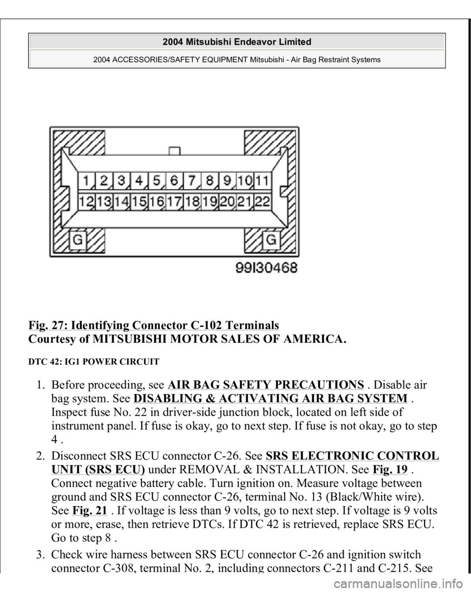
Fig. 27: Identifying Connector C
-102 Terminals
Courtesy of MITSUBISHI MOTOR SALES OF AMERICA.
DTC 42: IG1 POWER CIRCUIT 1. Before proceeding, see AIR BAG SAFETY PRECAUTIONS
. Disable air
bag system. See DISABLING & ACTIVATING AIR BAG SYSTEM
.
Inspect fuse No. 22 in driver-side junction block, located on left side of
instrument panel. If fuse is okay, go to next step. If fuse is not okay, go to step
4 .
2. Disconnect SRS ECU connector C-26. See SRS ELECTRONIC CONTROL
UNIT (SRS ECU)
under REMOVAL & INSTALLATION. See Fig. 19
.
Connect negative battery cable. Turn ignition on. Measure voltage between
ground and SRS ECU connector C-26, terminal No. 13 (Black/White wire).
See Fig. 21
. If voltage is less than 9 volts, go to next step. If voltage is 9 volts
or more, erase, then retrieve DTCs. If DTC 42 is retrieved, replace SRS ECU.
Go to step 8 .
3. Check wire harness between SRS ECU connector C-26 and ignition switch
connector C-308
, terminal No. 2
, includin
g connectors C-211 and C-215. See
2004 Mitsubishi Endeavor Limited
2004 ACCESSORIES/SAFETY EQUIPMENT Mitsubishi - Air Bag Restraint Systems
Page 394 of 3870
1. Connect scan tool to Data Link Connector (DLC). See INITIAL SRS
DIAGNOSTIC PROCEDURE
under DIAGNOSTICS. If scan tool is able to
diagnose CAN bus lines and CAN bus lines are satisfactory, go to next step. If
scan tool cannot diagnose CAN bus lines, repair CAN bus lines. Go to next
step.
2. Erase, then retrieve DTCs. If DTC B1475 is retrieved, replace SRS ECU. See
SRS ELECTRONIC CONTROL UNIT (SRS ECU)
under REMOVAL &
INSTALLATION. If DTC B1475 is not retrieved, an intermittent condition
may exist.
DTCB1476: POWER SUPPLY VOLTAGE DROPS ABNORMALLY 1. Connect scan tool to Data Link Connector (DLC). See INITIAL SRS
DIAGNOSTIC PROCEDURE
under DIAGNOSTICS. If scan tool is able to
diagnose CAN bus lines and CAN bus lines are satisfactory, go to next step. If
scan tool cannot diagnose CAN bus lines, repair CAN bus lines. Go to next
step.
2. Erase, then retrieve DTCs. Turn ignition off. If DTC B1476 is retrieved, go to
next step. If DTC B1476 is not retrieved, an intermittent condition may exist.
3. Remove fuse No. 22 from instrument panel junction block. See Fig. 39
. If fuse
is blown, go to step 6 . If fuse is not blown, go to next step.
4. Disconnect negative battery cable. Disconnect SRS ECU connector C-26. See
SRS ELECTRONIC CONTROL UNIT (SRS ECU)
under REMOVAL &
INSTALLATION. See Fig. 30
. Connect negative battery cable. Turn ignition
on. Measure voltage between ground and SRS ECU connector C-26, terminal
No. 23 (Black/White wire). If voltage is 9 volts or more, reconnect SRS
components. Erase, then retrieve DTCs. If DTC B1476 is retrieved, replace
SRS ECU. Go to step 8 . If DTC B1476 is not retrieved, go to next step.
5. Inspect Black/White wire between SRS ECU connector C-26, terminal No. 23
and ignition switch connector C-308, terminal No. 2. If wire is okay, go to step
8 . If wire is not okay, replace harness between SRS ECU and ignition switch.
Go to step 8 .
6. Replace fuse. Turn ignition on for one minute, then turn off. Inspect fuse. If
fuse is okay, go to step 8 . If fuse is not okay, go to next step.
7. Measure resistance between SRS ECU connector C-26
, terminal No. 23 and
2004 Mitsubishi Endeavor Limited
2004 ACCESSORIES/SAFETY EQUIPMENT Mitsubishi - Air Bag Restraint Systems
Page 395 of 3870
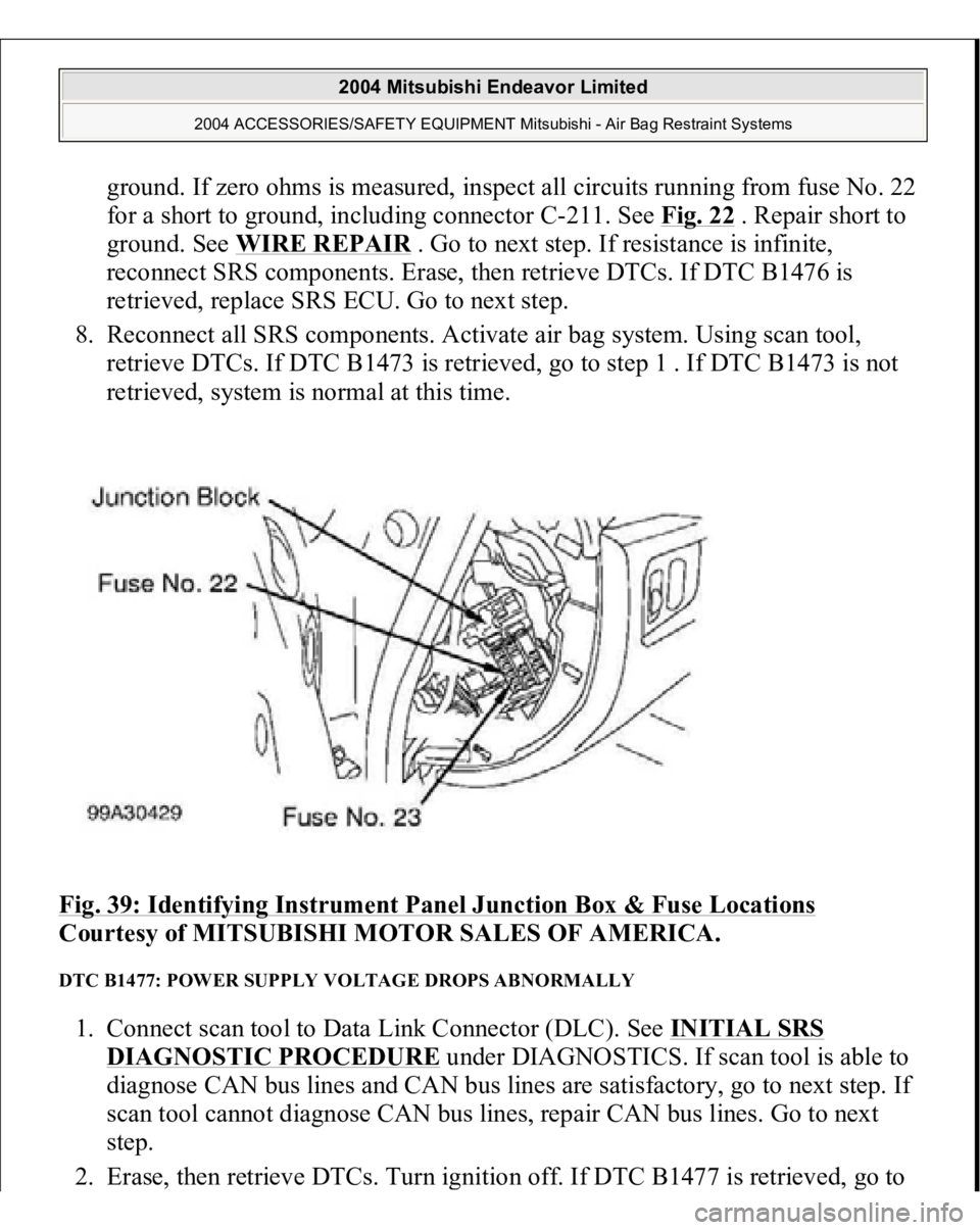
ground. If zero ohms is measured, inspect all circuits running from fuse No. 22
for a short to ground, including connector C-211. See Fig. 22
. Repair short to
ground. See WIRE REPAIR
. Go to next step. If resistance is infinite,
reconnect SRS components. Erase, then retrieve DTCs. If DTC B1476 is
retrieved, replace SRS ECU. Go to next step.
8. Reconnect all SRS components. Activate air bag system. Using scan tool,
retrieve DTCs. If DTC B1473 is retrieved, go to step 1 . If DTC B1473 is not
retrieved, system is normal at this time.
Fig. 39: Identifying Instrument Panel Junction Box & Fuse Locations
Courtesy of MITSUBISHI MOTOR SALES OF AMERICA.
DTC B1477: POWER SUPPLY VOLTAGE DROPS ABNORMALLY 1. Connect scan tool to Data Link Connector (DLC). See INITIAL SRS
DIAGNOSTIC PROCEDURE
under DIAGNOSTICS. If scan tool is able to
diagnose CAN bus lines and CAN bus lines are satisfactory, go to next step. If
scan tool cannot diagnose CAN bus lines, repair CAN bus lines. Go to next
step.
2. Erase, then retrieve DTCs. Turn ignition off. If DTC B1477 is retrieved,
go to
2004 Mitsubishi Endeavor Limited
2004 ACCESSORIES/SAFETY EQUIPMENT Mitsubishi - Air Bag Restraint Systems