wheel bolts MITSUBISHI ENDEAVOR 2004 Service Repair Manual
[x] Cancel search | Manufacturer: MITSUBISHI, Model Year: 2004, Model line: ENDEAVOR, Model: MITSUBISHI ENDEAVOR 2004Pages: 3870, PDF Size: 98.47 MB
Page 281 of 3870
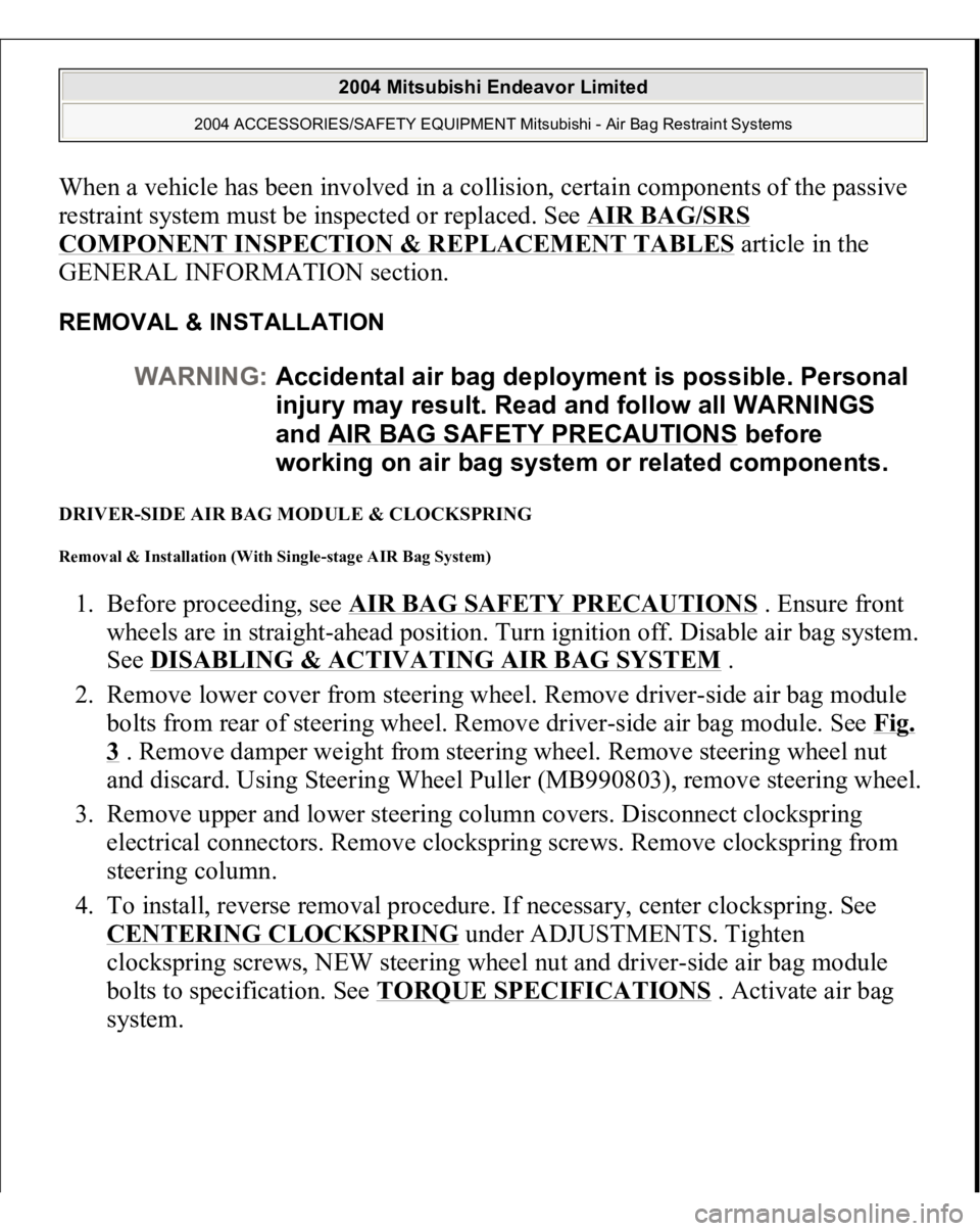
When a vehicle has been involved in a collision, certain components of the passive
restraint system must be inspected or replaced. See
AIR BAG/SRS
COMPONENT INSPECTION & REPLACEMENT TABLES
article in the
GENERAL INFORMATION section.
REMOVAL & INSTALLATION DRIVER-SIDE AIR BAG MODULE & CLOCKSPRING Removal & Installation (With Single-stage AIR Bag System) 1. Before proceeding, see
AIR BAG SAFETY PRECAUTIONS
. Ensure front
wheels are in straight-ahead position. Turn ignition off. Disable air bag system.
See
DISABLING & ACTIVATING AIR BAG SYSTEM
.
2. Remove lower cover from steering wheel. Remove driver-side air bag module
bolts from rear of steering wheel. Remove driver-side air bag module. See
Fig.
3 . Remove damper weight from steering wheel. Remove steering wheel nut
and discard. Using Steering Wheel Puller (MB990803), remove steering wheel.
3. Remove upper and lower steering column covers. Disconnect clockspring
electrical connectors. Remove clockspring screws. Remove clockspring from
steering column.
4. To install, reverse removal procedure. If necessary, center clockspring. See CENTERING CLOCKSPRING
under ADJUSTMENTS. Tighten
clockspring screws, NEW steering wheel nut and driver-side air bag module
bolts to specification. See
TORQUE SPECIFICATIONS
. Activate air bag
s
ystem. WARNING:Accidental air bag deployment is possible. Personal
injury may result. Read and follow all WARNINGS
and AIR BAG SAFETY PRECAUTIONS
before
working on air bag system or related components.
2004 Mitsubishi Endeavor Limited
2004 ACCESSORIES/SAFETY EQUIPMENT Mitsubishi - Air Bag Restraint Systems
Page 282 of 3870
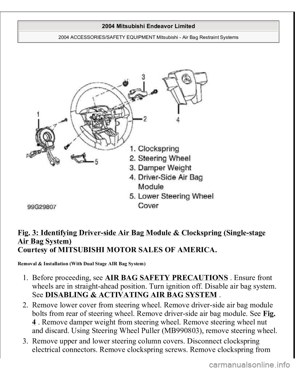
Fig. 3: Identifying Driver
-side Air Bag Module & Clockspring (Single
-stage
Air Bag System)
Courtesy of MITSUBISHI MOTOR SALES OF AMERICA.
Removal & Installation (With Dual Stage AIR Bag System) 1. Before proceeding, see
AIR BAG SAFETY PRECAUTIONS
. Ensure front
wheels are in straight-ahead position. Turn ignition off. Disable air bag system.
See
DISABLING & ACTIVATING AIR BAG SYSTEM
.
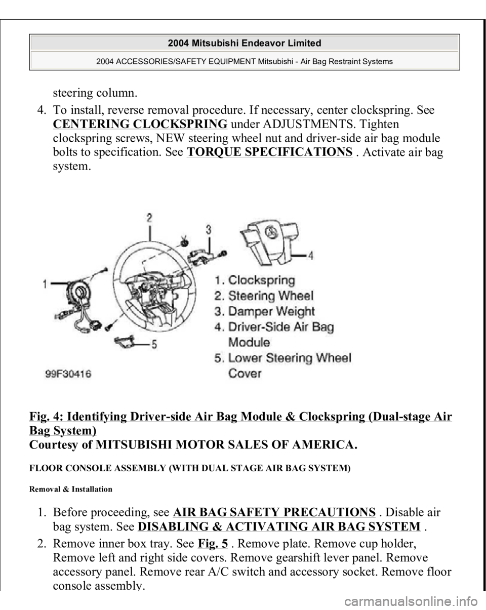
2. Remove lower cover from steering wheel. Remove driver-side air bag module
bolts from rear of steering wheel. Remove driver-side air bag module. See Fig.
4 . Remove damper weight from steering wheel. Remove steering wheel nut
and discard. Using Steering Wheel Puller (MB990803), remove steering wheel.
3. Remove upper and lower steering column covers. Disconnect clockspring
electrical connectors. Remove clocks
prin
g screws. Remove clocks
prin
g from
2004 Mitsubishi Endeavor Limited
2004 ACCESSORIES/SAFETY EQUIPMENT Mitsubishi - Air Bag Restraint Systems
Page 283 of 3870
steering column.
4. To install, reverse removal procedure. If necessary, center clockspring. See
CENTERING CLOCKSPRING
under ADJUSTMENTS. Tighten
clockspring screws, NEW steering wheel nut and driver-side air bag module
bolts to specification. See TORQUE SPECIFICATIONS
. Activate air bag
system.
Fig. 4: Identifying Driver
-side Air Bag Module & Clockspring (Dual
-stage Air
Bag System)
Courtesy of MITSUBISHI MOTOR SALES OF AMERICA.
FLOOR CONSOLE ASSEMBLY (WITH DUAL STAGE AIR BAG SYSTEM) Removal & Installation 1. Before proceeding, see AIR BAG SAFETY PRECAUTIONS
. Disable air
bag system. See DISABLING & ACTIVATING AIR BAG SYSTEM
.
2. Remove inner box tray. See Fig. 5
. Remove plate. Remove cup holder,
Remove left and right side covers. Remove gearshift lever panel. Remove
accessory panel. Remove rear A/C switch and accessory socket. Remove floor
console assembl
y.
2004 Mitsubishi Endeavor Limited
2004 ACCESSORIES/SAFETY EQUIPMENT Mitsubishi - Air Bag Restraint Systems
Page 287 of 3870
CONSOLE ASSEMBL
Y . Remove left and right A-pillar trim panels.
Remove hood lock release handle.
3. Remove end panel. See Fig. 8
. Remove driver-side knee bolster. Remove fog
light switch. Remove steering column upper and lower covers. Remove
combination meter assembly. Remove center panel assembly. Remove air
vents. Remove radio panel. Remove AC-heater control assembly.
4. Remove hazard warning switch. Remove console meter hood. Remove multi-
center display unit. Remove audio components. Remove glove box assembly.
Remove left and right speaker covers. Remove speakers. Disconnect
clockspring and steering column switch connectors. Remove photo sensor and
photo sensor clamp.
5. Remove interior temperature sensor. Disconnect passenger-side air bag module
connector. Remove left and right center instrument panel brackets. Disconnect
remaining electrical connectors. Remove instrument panel nuts and bolts.
Remove instrument panel.
6. To install, reverse removal procedure. Tighten NEW steering wheel nut and
drive
r-side air ba
g module bolts to s
pecification. Activate air ba
g system.
2004 Mitsubishi Endeavor Limited
2004 ACCESSORIES/SAFETY EQUIPMENT Mitsubishi - Air Bag Restraint Systems
Page 299 of 3870
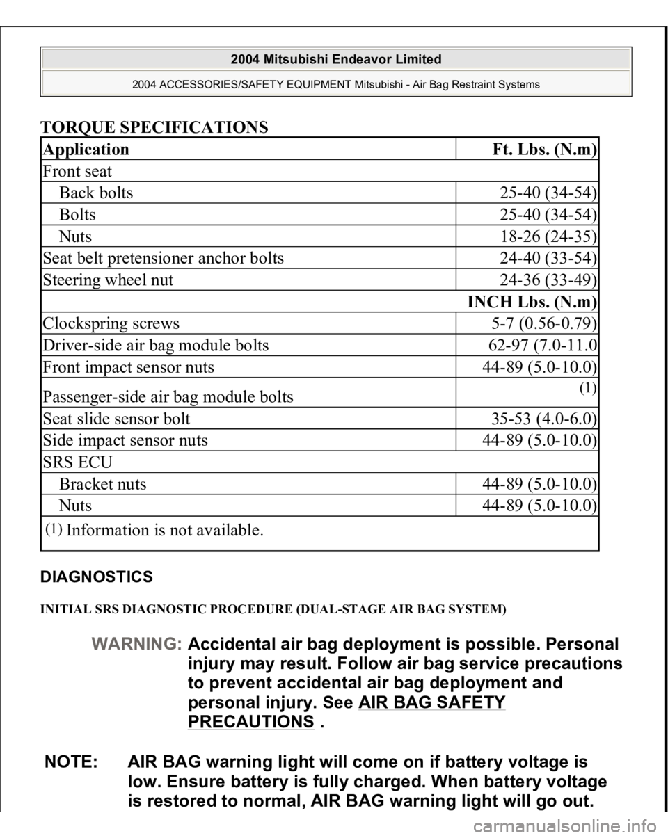
TORQUE SPECIFICATIONS DIAGNOSTICS INITIAL SRS DIAGNOSTIC PROCEDURE (DUAL-STAGE AIR BAG SYSTEM) Application
Ft. Lbs. (N.m)
Front seatBack bolts
25-40 (34-54)
Bolts
25-40 (34-54)
Nuts
18-26 (24-35)
Seat belt pretensioner anchor bolts
24-40 (33-54)
Steering wheel nut
24-36 (33-49)
INCH Lbs. (N.m)
Clockspring screws
5-7 (0.56-0.79)
Driver-side air bag module bolts
62-97 (7.0-11.0
Front impact sensor nuts
44-89 (5.0-10.0)
Passenger-side air bag module bolts
(1)
Seat slide sensor bolt
35-53 (4.0-6.0)
Side impact sensor nuts
44-89 (5.0-10.0)
SRS ECUBracket nuts
44-89 (5.0-10.0)
Nuts
44-89 (5.0-10.0)
(1)
Information is not available.
WARNING:Accidental air bag deployment is possible. Personal
in
jury ma
y result. Follow air ba
g service precautions
to prevent accidental air bag deployment and
personal injury. See AIR BAG SAFETY
PRECAUTIONS
.
NOTE: AIR BAG warning light will come on if battery voltage is
low. Ensure battery is fully charged. When battery voltage
is restored to normal, AIR BAG warning light will go out.
2004 Mitsubishi Endeavor Limited
2004 ACCESSORIES/SAFETY EQUIPMENT Mitsubishi - Air Bag Restraint Systems
Page 682 of 3870
ON
-VEHICLE SERVIC
E
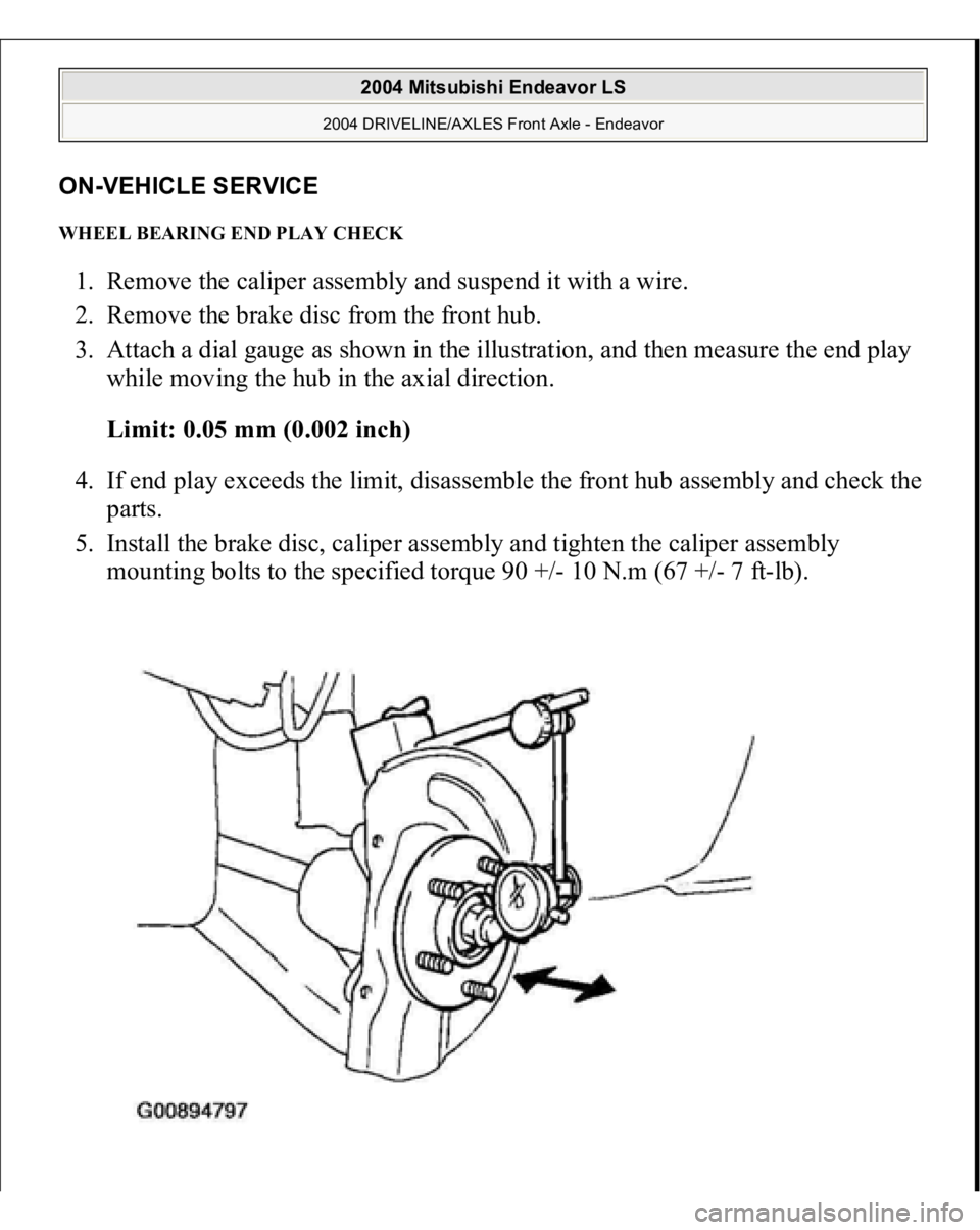
WHEEL BEARING END PLAY CHECK 1. Remove the caliper assembly and suspend it with a wire.
2. Remove the brake disc from the front hub.
3. Attach a dial gauge as shown in the illustration, and then measure the end play
while moving the hub in the axial direction.
Limit: 0.05 mm (0.002 inch)
4. If end play exceeds the limit, disassemble the front hub assembly and check the
parts.
5. Install the brake disc, caliper assembly and tighten the caliper assembly
mounting bolts to the specified torque 90 +/- 10 N.m (67 +/- 7 ft-lb).
2004 Mitsubishi Endeavor LS
2004 DRIVELINE/AXLES Front Axle - Endeavor
Page 683 of 3870
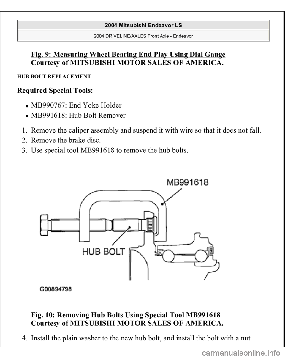
Fig. 9: Measuring Wheel Bearing End Play Using Dial Gauge
Courtesy of MITSUBISHI MOTOR SALES OF AMERICA.
HUB BOLT REPLACEMENT Required Special Tools:
MB990767: End Yoke Holder MB991618: Hub Bolt Remover
1. Remove the caliper assembly and suspend it with wire so that it does not fall.
2. Remove the brake disc.
3. Use special tool MB991618 to remove the hub bolts.
Fig. 10: Removing Hub Bolts Using Special Tool MB991618
Courtesy of MITSUBISHI MOTOR SALES OF AMERICA.
4. Install the
plain washer to the new hub bolt, and install the bolt with a nut
2004 Mitsubishi Endeavor LS
2004 DRIVELINE/AXLES Front Axle - Endeavor
Page 1592 of 3870
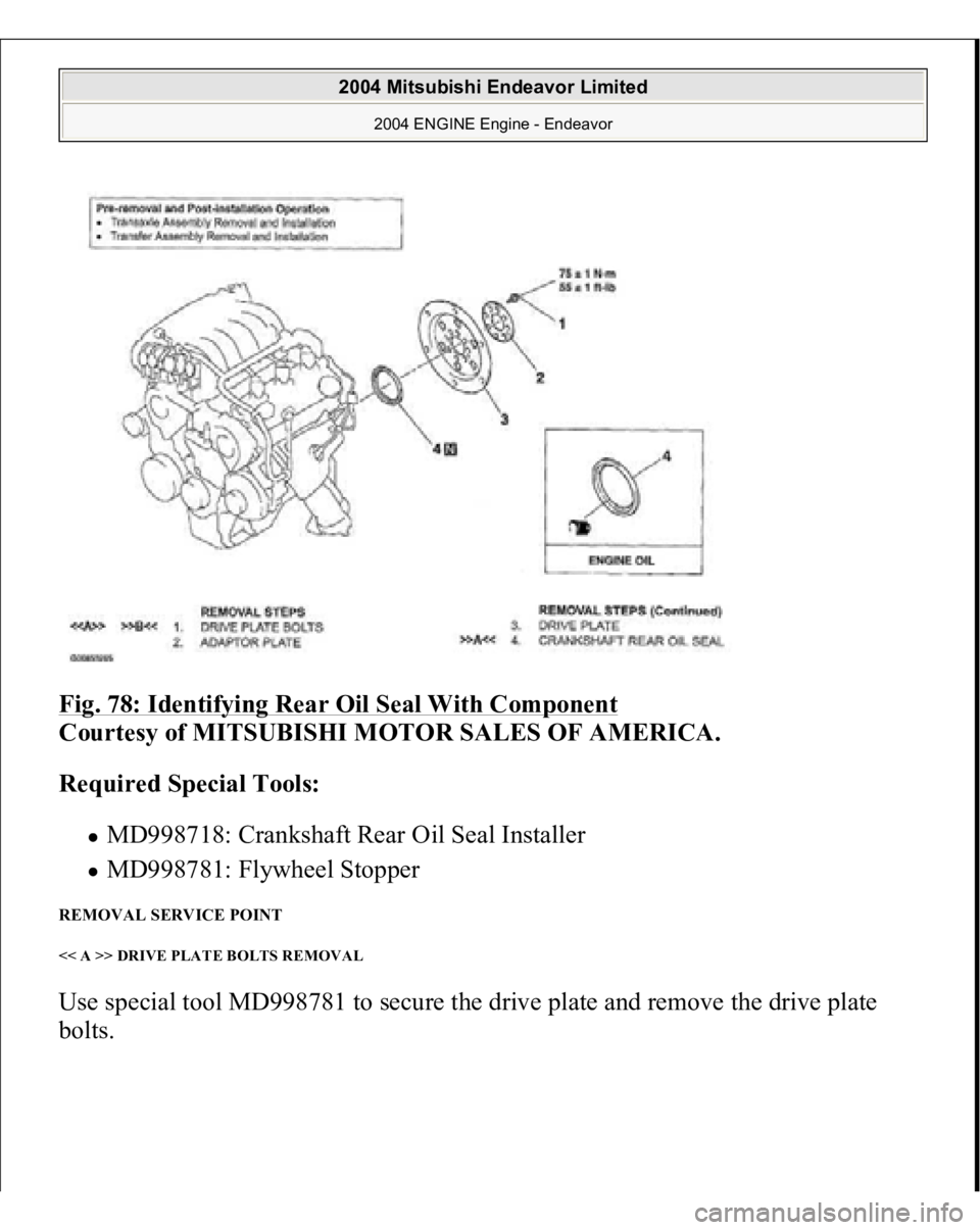
Fig. 78: Identifying Rear Oil Seal With Component
Courtesy of MITSUBISHI MOTOR SALES OF AMERICA.
Required Special Tools:
MD998718: Crankshaft Rear Oil Seal Installer MD998781: Flywheel Stopper
REMOVAL SERVICE POINT << A >> DRIVE PLATE BOLTS REMOVAL Use special tool MD998781 to secure the drive plate and remove the drive plate bolts.
2004 Mitsubishi Endeavor Limited
2004 ENGINE Engine - Endeavor
Page 2866 of 3870
5. Loosen the two lower steering column mounting bolts by two turns.
6. If there is any sign of looseness when the moveable bracket is moved back and
forth by hand, replace the steering column shaft assembly with a new one.
7. If no problem is found during the inspection, tighten the steering column
mounting bolts to the specified torque.
Tightening torque: 12 +/- 2 N.m (102 +/- 22 in-lb) STEERING WHEEL REMOVAL AND INSTALLATION Post-installation Operation
Checking Steering Wheel Position with Wheels Straight Ahead
WARNING:
Before removing the steering wheel and air bag
module assembly, refer to AIR BAG SAFETY PRECAUTIONS
and DRIVER
-SIDE AIR BAG
MODULE & CLOCKSPRING
or PASSENGER
-
SIDE AIR BAG MODULE
.
When removing and installing the steering
wheel, do not let it bump against the air bag
module.
2004 Mitsubishi Endeavor LS
2004 STEERING Power Steering - Endeavor
Page 2881 of 3870
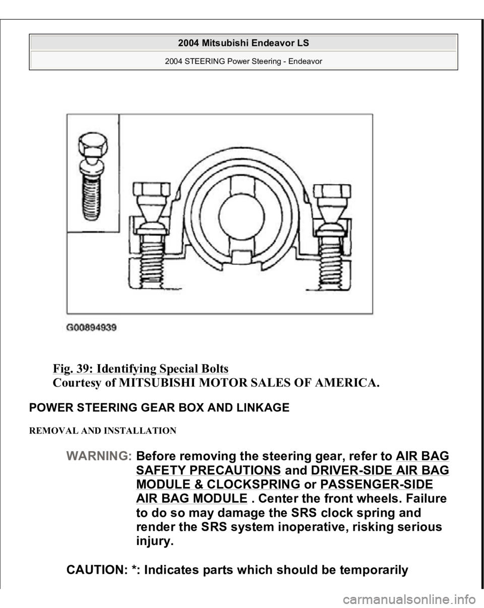
Fig. 39: Identifying Special Bolts
Courtesy of MITSUBISHI MOTOR SALES OF AMERICA.
POWER STEERING GEAR BOX AND LINKAGE REMOVAL AND INSTALLATION
WARNING:Before removing the steering gear, refer to AIR BAG
SAFETY PRECAUTIONS
and DRIVER
-SIDE AIR BAG
MODULE & CLOCKSPRING
or PASSENGER
-SIDE
AIR BAG MODULE
. Center the front wheels. Failure
to do so may damage the SRS clock spring and
render the SRS system inoperative, risking serious
injury.
CAUTION: *: Indicates parts which should be temporarily
2004 Mitsubishi Endeavor LS
2004 STEERING Power Steering - Endeavor