clutch MITSUBISHI GALANT 1989 Service Owners Manual
[x] Cancel search | Manufacturer: MITSUBISHI, Model Year: 1989, Model line: GALANT, Model: MITSUBISHI GALANT 1989Pages: 1273, PDF Size: 37.62 MB
Page 731 of 1273
AUTOMATIC TRANSAXLE
- Troubleshooting23-25
r star
P =
<
zzGsEa
c”65
srBZzi;4
1
1
Y-
a
s
s-
7
ii-
s-
3-1
z-
3
1_:5s
5
f-
d
1i
‘I3
E*aOm5s;K
;$2zIrg:,8
EP2.2
$2-
If
E:
p2zz0om,c .Gis:75’‘5$5oz28-
-
-
7-
_/-
4
X
?I-
92L”$ElE0
-
zmz
“$
P::g=f,i?Ppzz?$5.- -CE$2
gsi
-
= 0
0752=o-+u$Z
52
gEEO-
- nsaxl’
-
;
4
i?
3
b
$
:
b
?
mk?
::
w
nalfu-
f3::2?gmyQr0.3-J$GbG
LF!‘,
SO” c-
f35eL?g_mc?PV,L 0
.FnEC+8r35-
x-
,hlft-r-
if5 -0
::2Bg
z
5
Pz=$5
3
4
- ck la
- fte
T
z2
B5t8s,-55
P$%88,3d-
x
-i1
Is,
c
5
‘0mc
gi?
DEEf
ge‘2
c”d
p$
“=‘
EiumTNm,ci )th(
l-
jhO#
X-
-
-
-
XX
X-X-
-
-
g,-
X
-.
I
-
5cIpcg;UCa, 22,$ ‘cG$68-
gz
?&SiEss
555m$g
IcE-
?5g
26a2
_’s
8fsz
gD$;i058-cw3
5zYE8g$nso’51b’F m
asz fis-$2x-uo
E(1
9
-z
N
E2
2m-
z-
r 0
35fc2 .ss:!0=3;Pg-
xx--x-X-X-
-
-
-
-
x-
-
-
-
-
-
-
-
6F-
X
X
xX-
-
-
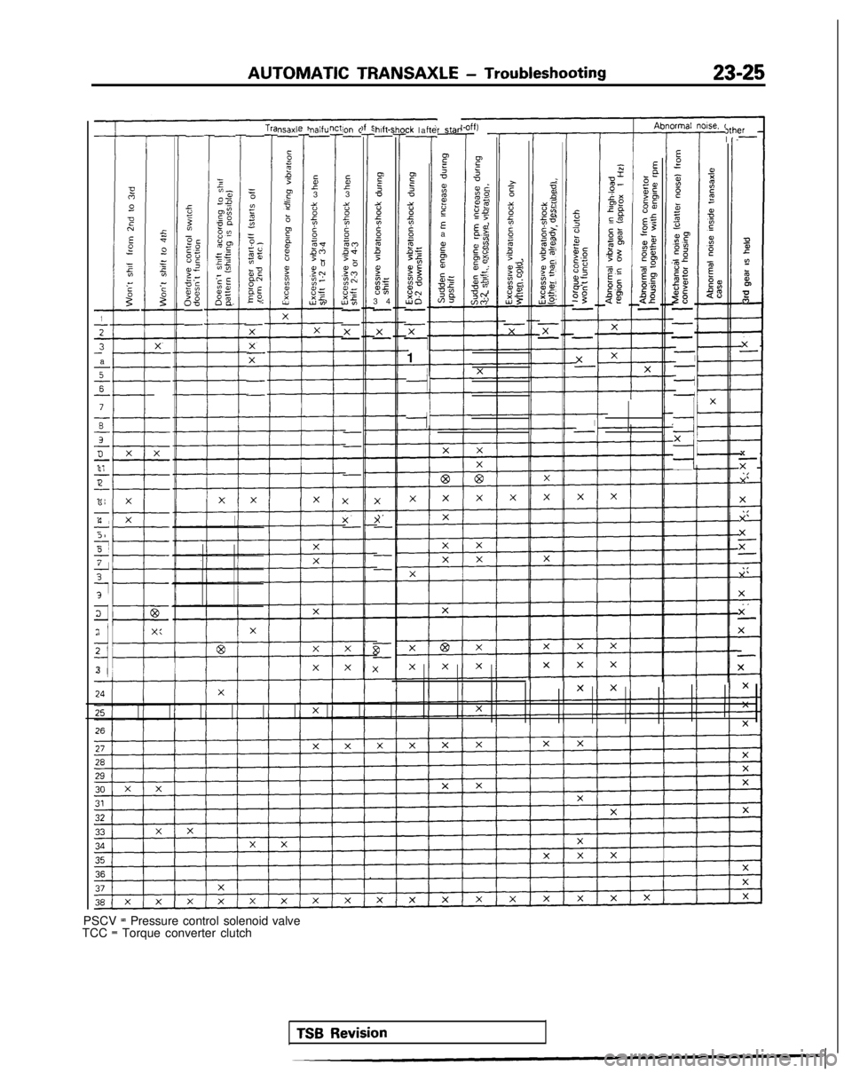
PSCV = Pressure control solenoid
TCC = Torque converter clutch
I-
X
TX
X
X
X
x- X
X
X-
X
-
X
valve
TSB Revision
Page 732 of 1273
23-26AUTOMATIC TRANSAXLE - Troubleshooting
HOT
TFA0715
AW
D
TFA0700
DATA LINK AND TEST
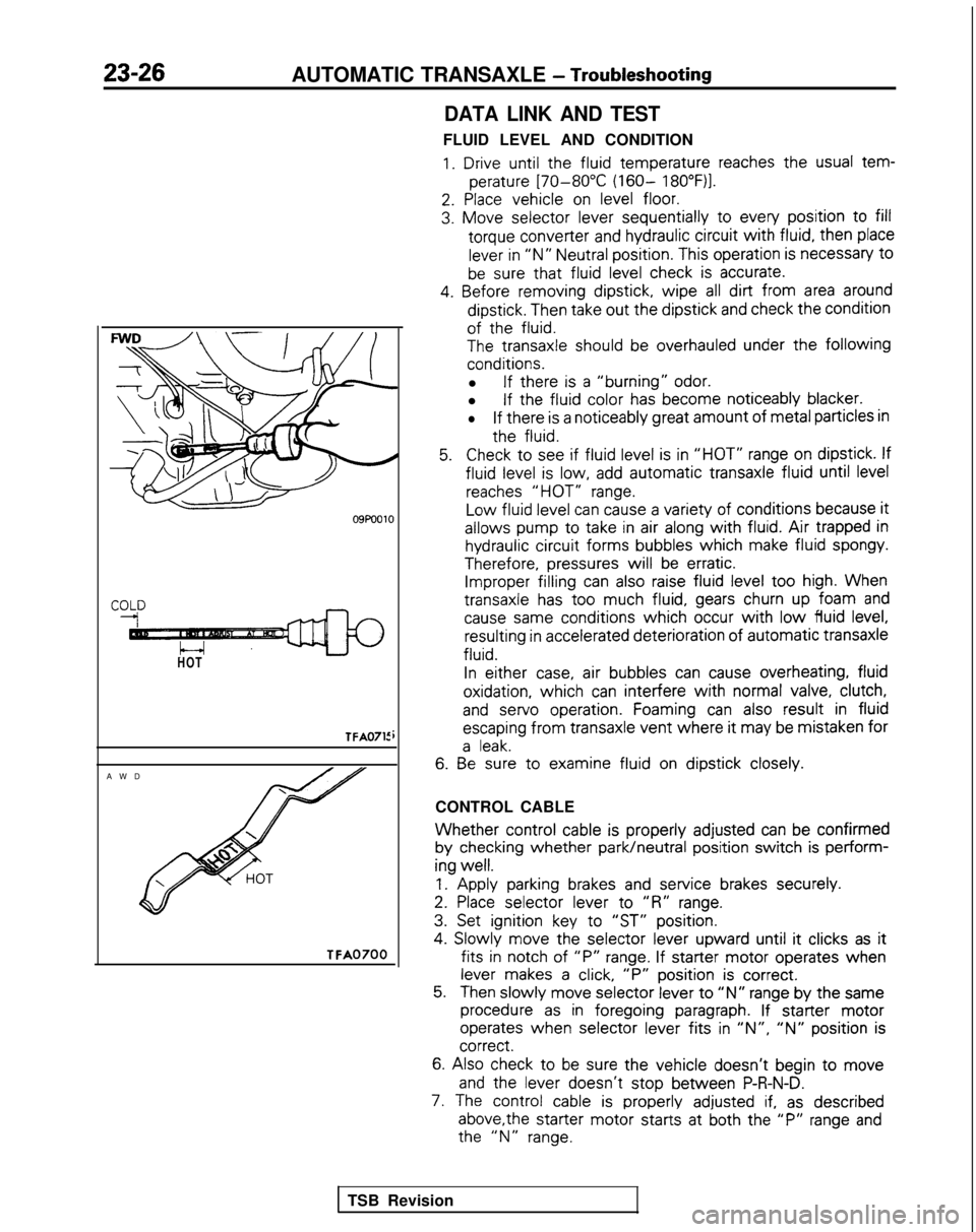
FLUID LEVEL AND CONDITION
1. Drive until the
fluid
temperature
reaches the
usual tem-
perature
[70-80°C (160- 18O”F)l.
2. Place
vehicle
on level floor.
3. Move
selector
lever sequentially
to
every
position
to fill
torque
converter
and hydraulic circuit
with fluid,
then
place
lever in “N” Neutral position.
This operation is necessary
t0
be sure that fluid
level check is accurate.
4. Before
removing
dipstick,
wipe all dirt from area around
dipstick.
Then take out
the
dipstick
and check the
condition
of the
fluid.
The
transaxle
should be overhauled under the following
conditions.
l If there
is a “burning” odor.
l If the
fluid
color
has become
noticeably
blacker.
lIf there
is a noticeably
great
amount
of metal particles in
the
fluid.
5.Check to
see if fluid
level is in “HOT” range on dipstick.
If
fluid
level is low, add automatic
transaxle
fluid
until level
reaches “HOT” range.
Low
fluid
level can cause a variety of
conditions
because it
allows
pump
to
take
in air along with fluid. Air trapped in
hydraulic circuit
forms
bubbles
which
make fluid
spongy.
Therefore,
pressures
will be erratic. Improper filling
can also raise fluid level too
high. When
transaxle
has too
much fluid,
gears churn up foam and
cause same
conditions
which occur with low fluid
level, resulting
in accelerated deterioration
of
automatic
transaxle
fluid.
In
either
case, air bubbles
can cause overheating,
fluid
oxidation,
which can interfere
with normal valve, clutch,
and
servo
operation.
Foaming can also result
in fluid
escaping
from
transaxle
vent where it
may be mistaken
for
a leak.
6. Be
sure to
examine
fluid
on dipstick
closely.
CONTROL CABLE
Whether control
cable is properly
adjusted
can be confirmed
by
checking
whether park/neutral
position
switch is perform-
ing
well.
1.
Apply
parking brakes and service
brakes securely.
2. Place
selector
lever
to
“R” range.
3. Set ignition
key to
“ST” position.
4.
Slowly
move
the
selector
lever
upward
until it
clicks as it
fits in
notch of “P” range. If starter
motor
operates
when
lever makes a click, “P”
position
is correct.
5.Then slowly
move
selector
lever to “N” range by
the
same
procedure as in foregoing
paragraph. If starter
motor
operates
when selector
lever
fits in ‘IN”, “N” position
is correct.
6.
Also check to be sure the
vehicle
doesn’t
begin to move
and
the
lever
doesn’t
stop
between
P-R-N-D.
7. The control
cable is properly
adjusted if, as described
above,the
starter
motor
starts
at both the
“P” range and the
“N” range.
TSB Revision
Page 735 of 1273
AUTOMATIC TRANSAXLE - Troubleshootina
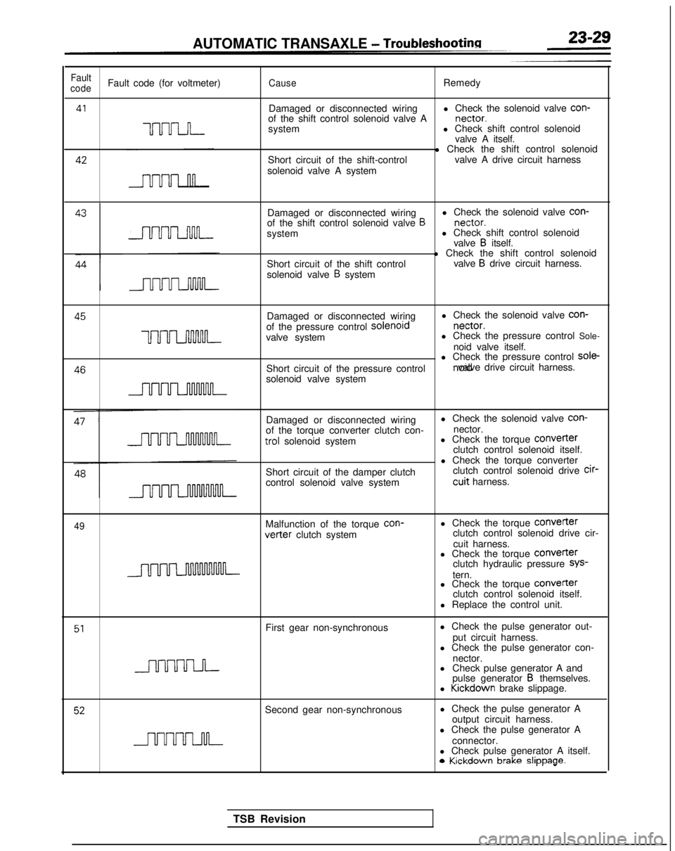
Fault
codeFault code (for voltmeter)CauseRemedy
41
UUU-LJ-I-
Damaged or disconnected wiring l Check the solenoid valve con-
of the shift control solenoid valve A nectar.
system l Check shift control solenoid
valve A itself. 42
Short circuit of the shift-control
solenoid valve A system l Check the shift control solenoid
valve A drive circuit harness
Damaged or disconnected wiring l Check the solenoid valve con-
of the shift control solenoid valve
B nectar.
system l Check shift control solenoid
valve
B itself.
Short circuit of the shift control
solenoid valve
B system l Check the shift control solenoid
valve
B drive circuit harness. 45
Damaged or disconnected wiringl Check the solenoid valve con-
of the pressure control solenord nectar.
uuuLnnnM-valve system
l Check the pressure control Sole-
noid valve itself. 46
l Check the pressure control sole-
Short circuit of the pressure control noid valve drive circuit harness.
solenoid valve system
Damaged or disconnected wiring
of the torque converter clutch con- trol
solenoid system
Short circuit of the damper clutch
control solenoid valve system l Check the solenoid valve con-
nector.
l Check the torque COnVeIter
clutch control solenoid itself.
l Check the torque converter clutch control solenoid drive cir-
cuit harness.
49Malfunction of the torque
con-vetter clutch system
l Check the torque
Converterclutch control solenoid drive cir-
cuit harness.
l Check the torque
COnVeITerclutch hydraulic pressure SYS-
tern.
l Check the torque COnVerter
clutch control solenoid itself.
l Replace the control unit.
51First gear non-synchronous l Check the pulse generator out-
put circuit harness.
l Check the pulse generator con-
nector.
l Check pulse generator A and
pulse generator
B themselves.
l Kickdown
brake slippage.
52Second gear non-synchronous l Check the pulse generator A
output circuit harness.
l Check the pulse generator A
connector.
l Check pulse generator A itself. 0
Kickdown brake slippage.
TSB Revision
Page 736 of 1273
23-30AUTOMATIC TRANSAXLE - Troubleshooting
l Check the pulse generator Aoutput circuit harness.
0Check the pulse venerator
con- nectar.
-l Check pulse generator A andpulse generator B themselves.
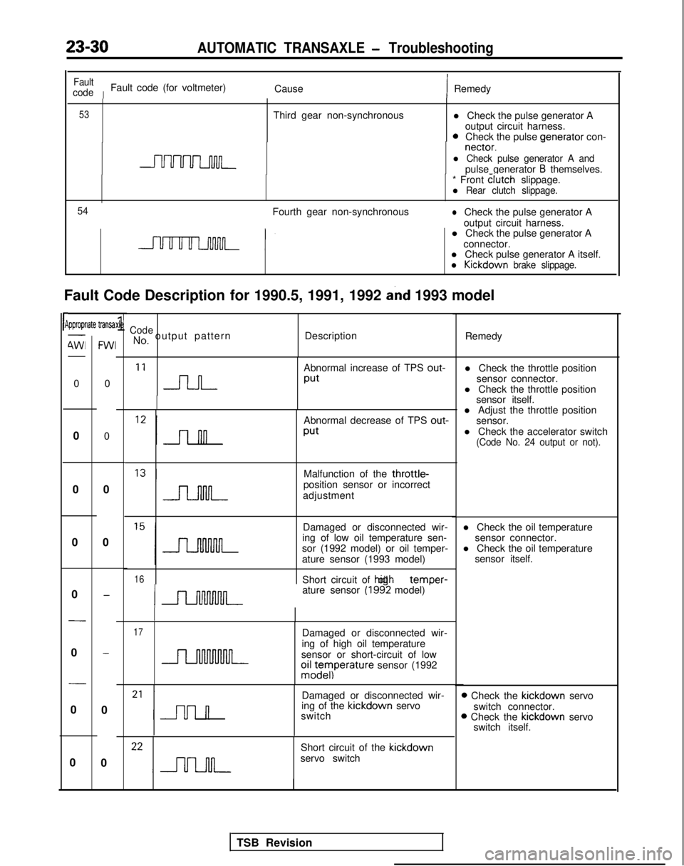
Fault Code Description for 1990.5, 1991, 1992
and 1993 model
rP
Fault
code
IFault code (for voltmeter) CauseIRemedy
53Third gear non-synchronous
* Front clutch
slippage.
l Rear clutch slippage.
54
Fourth gear non-synchronouslCheck the pulse generator A
output circuit harness.
l Check the pulse generator A
connector.
l Check pulse generator A itself.
l Kickdown brake slippage.
ipproprlate transa-
4Wl-
0
0
0
0
0
-
0
-
0
0
FWI
0
0
0
0
-
-
0
0
xle1CodeNo, output pattern Description
Remedy
‘I n
Abnormal increase of TPS out-
Put
Abnormal decrease of TPS out-
Put
l Adjust the throttle position
sensor.
l Check the accelerator switch
(Code No. 24 output or not).
Malfunction of the throttle-position sensor or incorrect
adjustment
Damaged or disconnected wir-
ing of low oil temperature sen- l Check the oil temperature
sensor connector.
sor (1992 model) or oil temper- l Check the oil temperature
ature sensor (1993 model) sensor itself.
16Short circuit of hiah oil temDer-
ature sensor (1992 model) ’
17Damaged or disconnected wir-
ing of high oil temperature
sensor or short-circuit of low
oiz;eyIperature sensor (1992
Damaged or disconnected wir-
ing of the kickdown
servo
switch
Short circuit of the kickdown
servo switch l Check the throttle position
sensor connector.
l Check the throttle position sensor itself.
D Check the kickdown
servo
switch connector.
B Check the kickdown
servo
switch itself.
TSB Revision
Page 737 of 1273
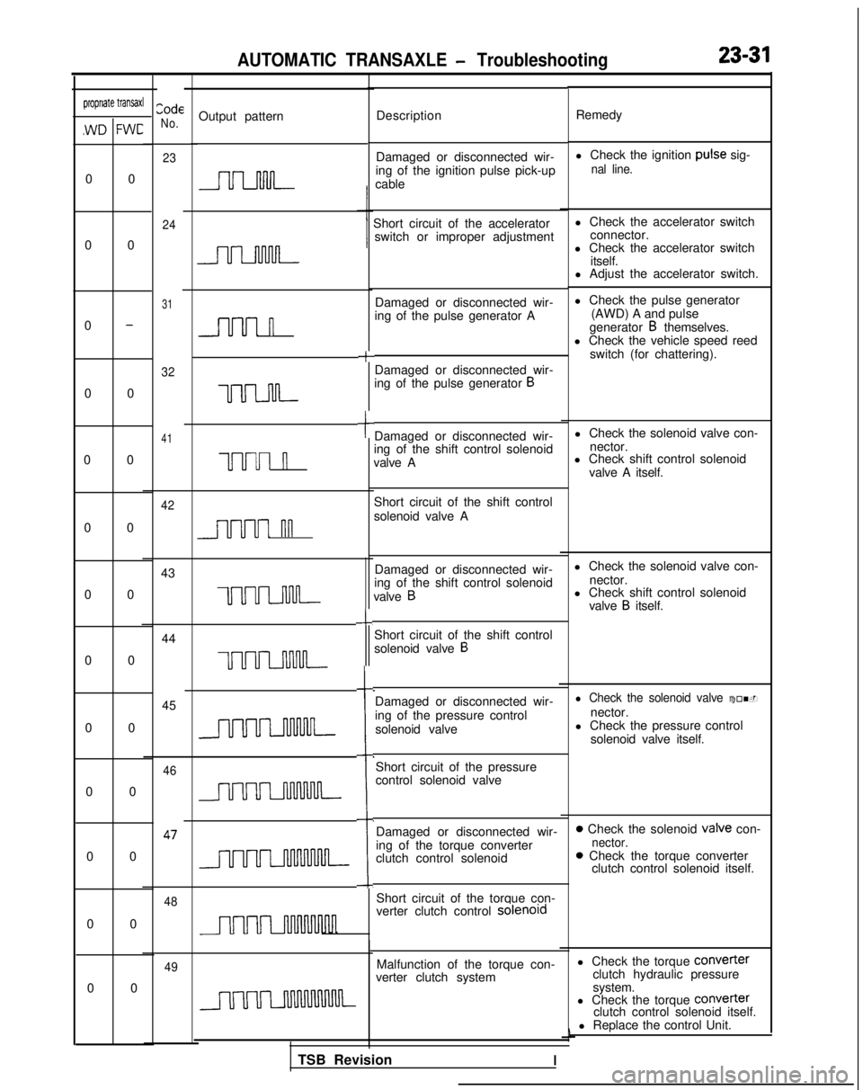
AUTOMATIC TRANSAXLE - Troubleshooting23-31
CodeNo.propriate transaxl
,WD FWC
Output pattern Description Remedy
Damaged or disconnected wir-
ing of the ignition pulse pick-up
cable l Check the ignition
puke sig-
nal line.
Short circuit of the accelerator
l Check the accelerator switch
switch or improper adjustment connector.
l Check the accelerator switch
itself.
l Adjust the accelerator switch.
Damaged or disconnected wir-
ing of the pulse generator A
+
l Check the pulse generator
(AWD) A and pulse
generator
B themselves.
l Check the vehicle speed reed
switch (for chattering).
Damaged or disconnected wir-
ing of the pulse generator
B
tDamaged or disconnected wir-
ing of the shift control solenoid
valve A l Check the solenoid valve con-
nector.
l Check shift control solenoid
valve A itself.
Short circuit of the shift control
solenoid valve A
Damaged or disconnected wir-
ing of the shift control solenoid
valve
B
l Check the solenoid valve con- nector.
-L
l Check shift control solenoidvalve B itself.
Short circuit of the shift control
solenoid valve
B
i
Damaged or disconnected wir-
ing of the pressure control solenoid valvel Check the solenoid valve con-
nector.
l Check the pressure control
solenoid valve itself.
Short circuit of the pressure
control solenoid valve
Damaged or disconnected wir-
ing of the torque converter
clutch control solenoid
0 Check the solenoid valve con-nector.0 Check the torque converter clutch control solenoid itself.
Short circuit of the torque con-
verter clutch control solenord
Malfunction of the torque con-
verter clutch system l Check the torque COnVefter
clutch hydraulic pressure
system.
0 0
0 0
0
-
0 0
0 0
0 00 00 0
0 0 0 0
0 0
0 00 0
23
24
31
32
41
n
uuuul
UUUI n
42
nn
43
uum
44 45
uum
46 47
48
TSB RevisionI
l Check the torque
Converter
clutch control solenoid itself.
l Replace the control Unit.
49
Page 738 of 1273
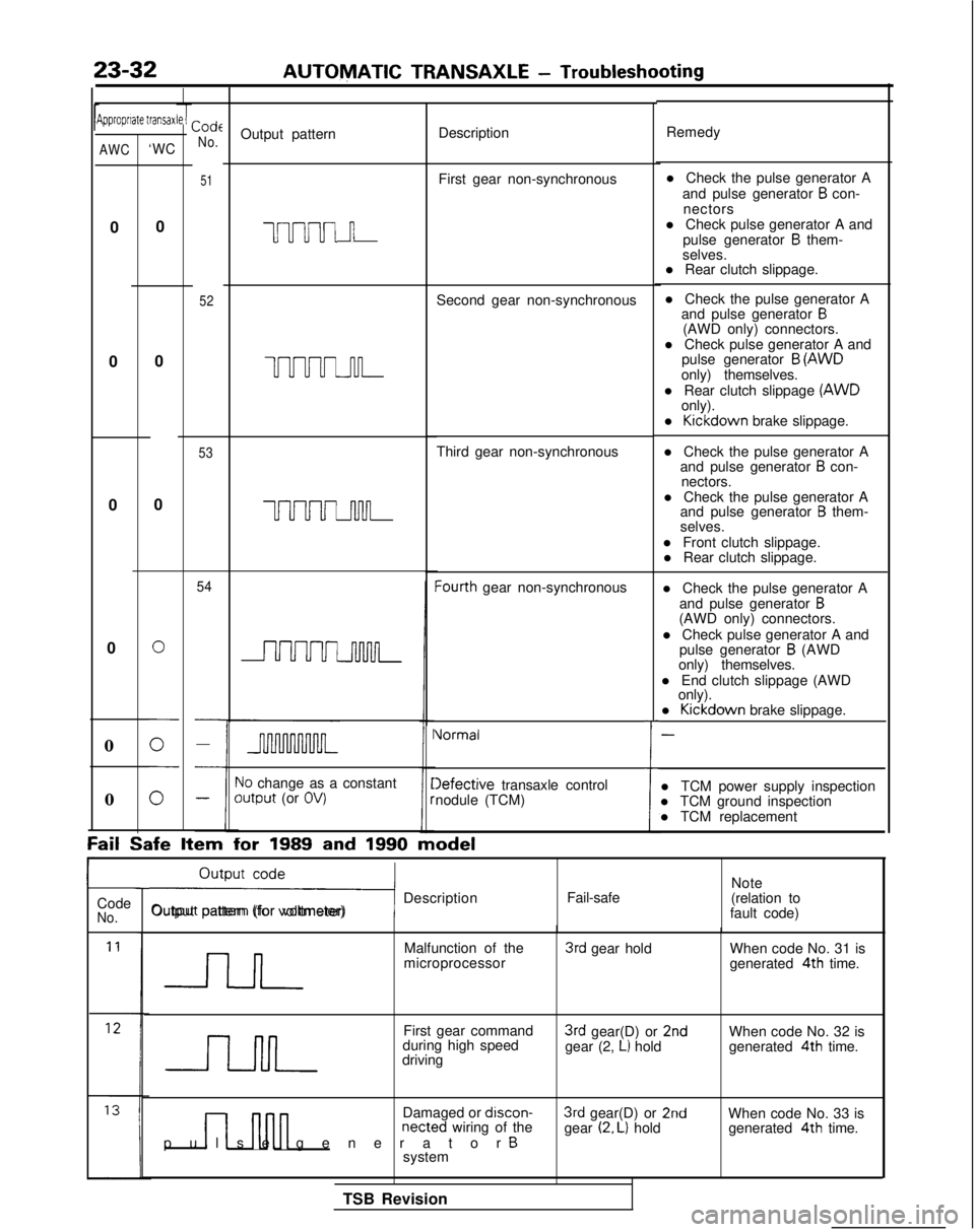
23-32AUTOMATIC TRANSAXLE
- Troubleshooting
Jipproprrate transaxCode
No.Output pattern Description
Remedy
51First gear non-synchronous
uuuul n
52Second gear non-synchronous l Check the pulse generator A
and pulse generator
B con-
nectors
l Check pulse generator A and pulse generator
B them-
selves.
l Rear clutch slippage.
l Check the pulse generator A and pulse generator
B(AWD only) connectors.
l Check pulse generator A and pulse generator
B (AWD
only) themselves.
l Rear clutch slippage (AWD
only).
l Kickdown
brake slippage.
l Check the pulse generator A and pulse generator
B con-
nectors.
l Check the pulse generator A and pulse generator
B them-
selves.
l Front clutch slippage. l Rear clutch slippage.
l Check the pulse generator A and pulse generator
B(AWD only) connectors.
l Check pulse generator A and pulse generator
B (AWD
only) themselves.
l End clutch slippage (AWD only).
l Kickdown
brake slippage.
-
l TCM power supply inspection
l TCM ground inspection
l TCM replacement
AWC‘WC
0
0 0
0
0
UUUUJ-u-l-
53Third gear non-synchronous
0
0
UUUUuwL
54Iourth gear non-synchronous
0
i
Vormal
10 change as a constantoutput (or OV)Iefective transaxle control
nodule (TCM)
0
Fail Safe
Item for
1989 and 1990 model
ri Description
Output pattern (for voltmeter) Fail-safeNote
(relation to
fault code)
Code
No.
Malfunction of the
microprocessor3rd gear hold When code No. 31 is
generated 4th
time.
First gear command
during high speed
driving
3rd gear(D) or 2ndgear (2, L) hold When code No. 32 is
generated 4th
time.
n nnn
Damaged or discon-netted wiring of the
pulse generator Bsystem
3rd gear(D) or 2ndgear (2. L) hold When code No. 33 is
generated 4th
time.
TSB Revision
Page 741 of 1273
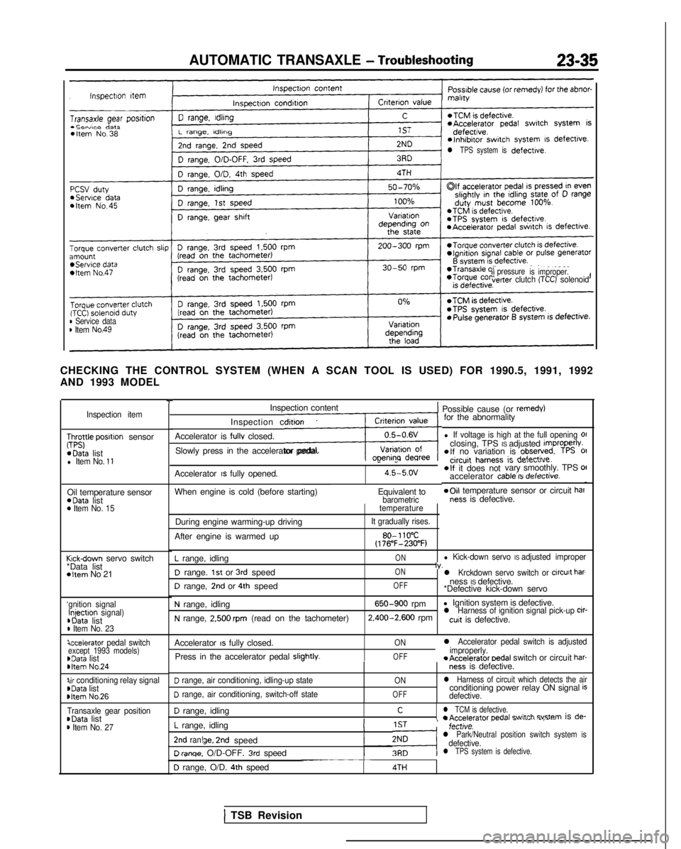
AUTOMATIC TRANSAXLE - Troubleshooting23-35
l TPS system isdefective.
ilpressure
is improper.verter clutch (TCC) solenoid
B Service datam Item No.49
CHECKING THE CONTROL SYSTEM (WHEN A SCAN TOOL IS USED) FOR 1990.5, 199\
1, 1992
AND 1993 MODEL
Inspection item
;;;yle posrtion sensor *Data
list
l Item No. 11
Oil temperature sensor *Data
list
0 Item No. 15
Krck-down servo switch
*Data list
*Item No 21
‘gnition signalInjectron signal) ,Data
list
D Item No. 23
iccelerator pedal switchexcept 1993 models)~Data listbItem No.24
Qr conditioning relay signalrData list rltem
No.26
Transaxle gear position~Data listm Item No. 27
-rInspection content
Inspection condition
Accelerator is
fullv closed.
LSlowly press in the accelerator pedal.
1 Possible cause (or remedy)for the abnormality
l If voltage is high at the full opening 01closing, TPS IS adjusted improperlv.elf no variation is observed. TPS 01
Accelerator IS fully opened.
--circuit harness ic r(afndi
O,a “ClrULIIu.
4.5-5.ov*If it does not vary smoothly. TPS OII- .-d-L__.:__accelerator cable IS oerectrve.
When engine is cold (before starting)
Equivalent to*Oil temperature sensor or circuit barbarometricness is defective.
During engine warming-up driving
After engine is warmed uptemperature
It gradually rises.
80- 110°C(176”F-230°F)
L range, idling
D range. 1st or 3rd speed
D range, 2nd or 4th speed
ON
ON
OFFl Kick-down servo IS adjusted improperIv.l Krckdown servo switch or circurt barness IS defective.
*Defective kick-down servo
N range, idling
N range, 2.500 rpm (read on the tachometer)
650-900 rpm l Ignition system is defective. 2.400-2.600
rpml Harness of ignition signal pick-up cir-cuit is defective.
Accelerator
IS fully closed.
Press in the accelerator pedal
sliphtlv.I
ON
OFF
l Accelerator pedal switch is adjusted
improperly. *Accelerator
oedal switch or circuit har-ness is defective.
D range, air conditioning, idling-up state
D range, air conditioning, switch-off state
ON
OFF
l Harness of circuit which detects the airconditioning power relay ON signal isdefective.
D range, idling
L range, idling
Cl TCM is defective.r A~d~r~tnr nednl +witch svstem is de-
!IST, -;,,tl;;..- r..--. -.-.--..
-,---,.,.,.,.v.l Park/Neutral position switch system isdefective.2nd ran!ge. 2nd speed
D renqe. O/D-OFF. 3rd speedl TPS system is defective.-~~~~~D range, O/D. 4th speed4TH
1 TSB Revision
Page 742 of 1273
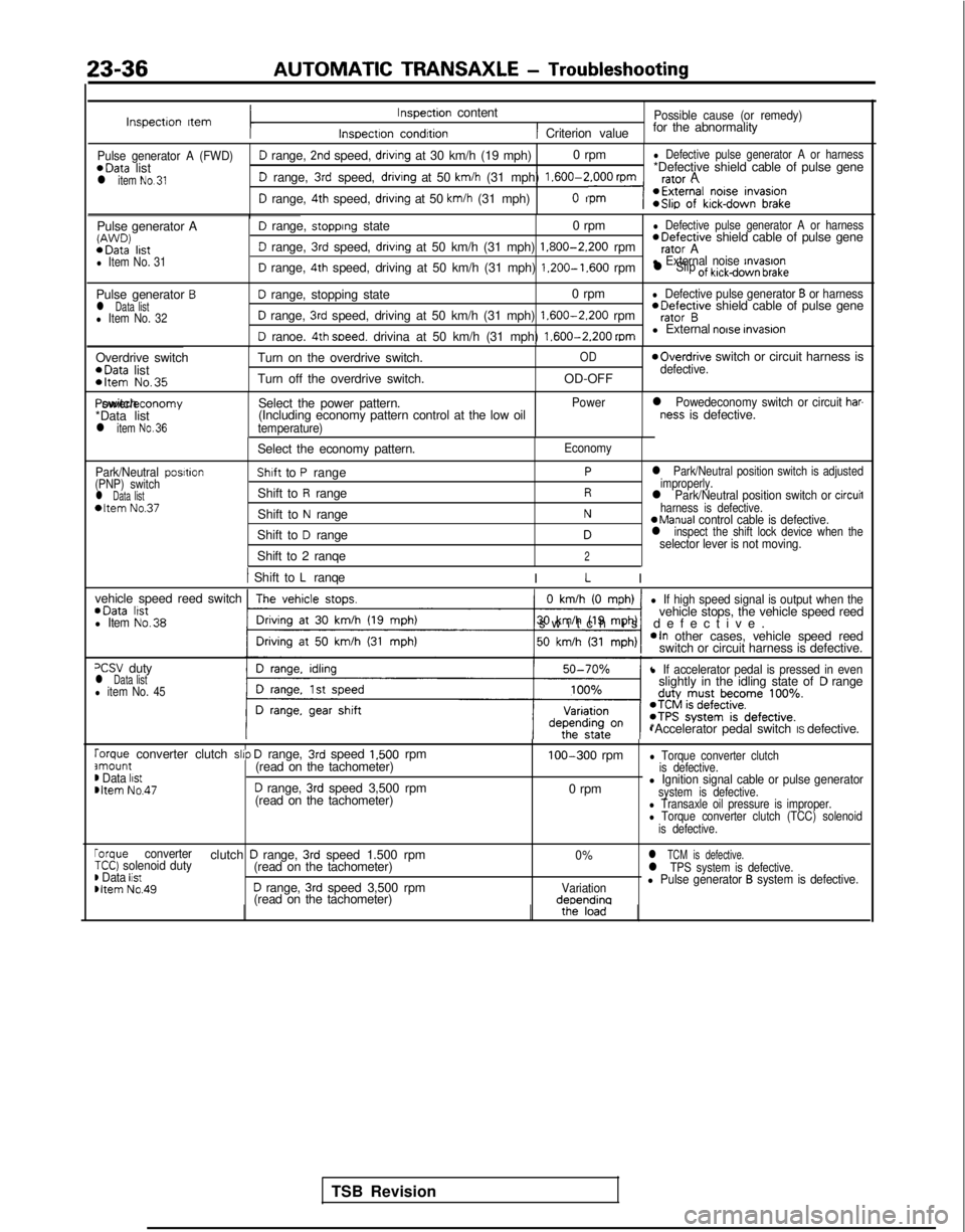
23-36AUTOMATIC TRANSAXLE
- Troubleshooting
Inspectron ItemInspection content
Inspectron condrtion
Possible cause (or remedy)
1 Criterion valuefor the abnormality
Pulse generator A (FWD)D range, 2nd speed, drivrng at 30 km/h (19 mph)
0 rpml Defective pulse generator A or harness*Data
list *Defective shield cable of pulse gene
l item No.31D range, 3rd speed, drivrng at 50 km/h (31 mph) 1.600-2.000
rpmrafnr A
D range, 4th speed, driving at 50 km/h (31 mph)n
Pulse generator AW’J’JD) *Data
lrstl Item No. 31
D range, stopprng state 0 rpml Defective pulse generator A or harness *Defective
shield cable of pulse gene
D range, 3rd speed, drivrng at 50 km/h (31 mph) 1.800-2.200
rpmrator A
D range, 4th speed, driving at 50 km/h (31 mph) 1.200-1.600
rpml External noise rnvasronl Slip of kickdown brake
Pulse generator Bl Data listl Item No. 32
D range, stopping state 0 rpml Defective pulse generator B or harness
D range, 3rd speed, driving at 50 km/h (31 mph) 1.600-2.200
rpm *Defective
shield cable of pulse generator B
D ranoe. 4th soeed. drivina at 50 km/h (31 mph) 1.600-2.200
mml External noise invasron
Overdrive switch *Data
list
*Item No.35
Turn on the overdrive switch.
Turn off the overdrive switch.OD
OD-OFF
moverdrive switch or circuit harness isdefective. Power/economy switch
*Data list
l item No.36
Select the power pattern.
(Including economy pattern control at the low oil
temperature) Power
l Powedeconomy switch or circuit har-ness is defective.
Park/Neutral posrtion
(PNP) switch
l Data list*Item No.37
Select the economy pattern.
Shaft to P range
Shift to
R range
Shift to
N range
Shift to
D range
Shift to 2 ranqe
Economy
Pl Park/Neutral position switch is adjusted
improperly.
Rl Park/Neutral position switch or circuil
Nharness is defective.aManual control cable is defective.Dl inspect the shift lock device when theselector lever is not moving.2
1 Shift to L ranqe
I L I
vehicle speed reed switch *Data
lrstl Item No.38
0 km/h (0 mph)
-1
l If high speed signal is output when thevehicle stops, the vehicle speed reed
switch is defective
.
*In other cases, vehicle speed reed
switch or circuit harness is defective.
=CSV dutyl Data listl item No. 45
l If accelerator pedal is pressed in evenslightly in the idling state ofD range
*Accelerator pedal switch IS defective.
rorque converter clutch slrp D range, 3rd speed 1,500 rpmamount(read on the tachometer)m Data listmltem No.47D range, 3rd speed 3,500 rpm
(read on the tachometer) 100-300
rpm
0 rpm
l Torque converter clutch
is defective.
l Ignition signal cable or pulse generatorsystem is defective.l Transaxle oil pressure is improper.l Torque converter clutch (TCC) solenoid
is defective.
rorque converterclutch D range, 3rd speed 1.500 rpm0%l TCM is defective.TCC) solenoid duty(read on the tachometer)) Data listl TPS system is defective.
Dltem No.49D range, 3rd speed 3,500 rpmVariationl Pulse generator B system is defective.
(read on the tachometer)deoendina
TSB Revision
Page 743 of 1273
AUTOMATIC TRANSAXLE - Troubleshooting23-37
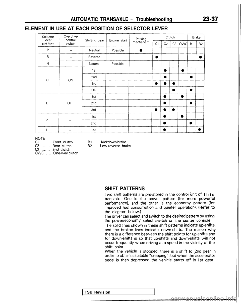
ELEMENT IN USE AT EACH POSITION OF SELECTOR LEVER
NOTECl. . . . . . . . .FrontclutchC2 . . . . . . . . .Rear clutchC3 . . . . . . . . .EndclutchOWC . . . . . . One-way clutchBl
. . . . . . Kickdown brake82 .._.. Low-reverse brake
SHIFT PATTERNS
Two
shift patterns
are pm-stored
in the
control
‘unit of
this transaxle.
One is the
power
pattern
(for more powerful
performance), and
the
other
is the
economy
pattern
(for
improved
fuel consumption
and quieter
operation).
(Refer to
the
diagram below.)
The
driver
can select
and switch to the
desired
pattern
by
using
the
power/economy
select
switch on the
center
console.
The solid lines
shown
in these
shift patterns
indicate
up-shifts,
and
the
broken lines indicate. down-shifts. The reason why there
is a difference
between
the
shift points for
up-shifts
and for
down-shifts is so that up-shifts
and down-shifts will not
occur frequently
when
driving
at
a speed in the
vicinity of the
shift
point.
When the
vehicle
is stopped,
there
is a shift to -2nd gear
in order
to
obtain
a suitable
“creeping”, but
when the accelerator
pedal is
then
depressed
the
vehicle
starts
off in 1st gear.
TSB Revision
Page 754 of 1273
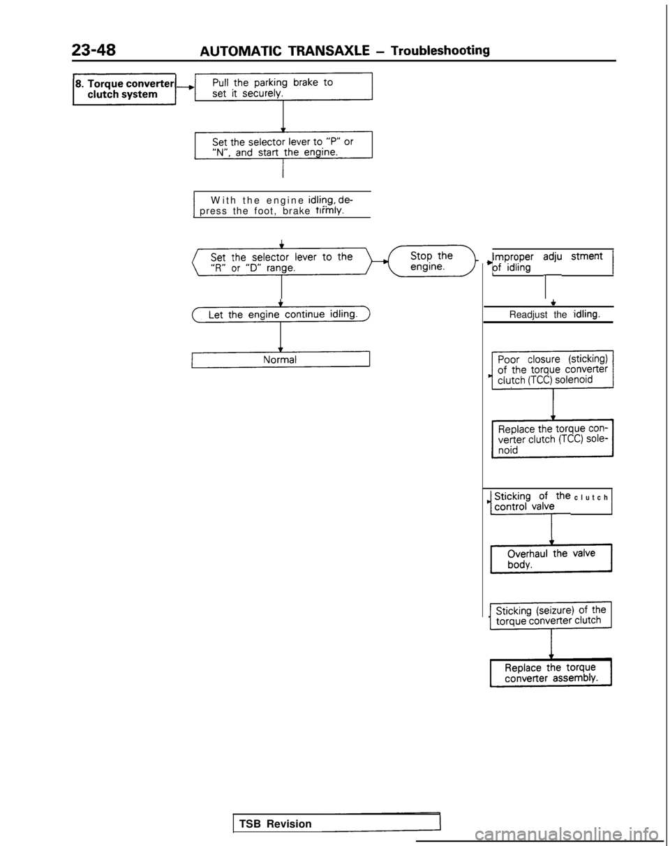
23-48AUTOMATIC TRANSAXLE
- Troubleshooting
1 press the foot, brake firmly.1W
ith the engine
idliqg, de-
Let the engine continue idling.
3
TSB Revision
4;ry;pn”g’ y stment 1
+
Readjust the ,idling.
1 ~i$.;h~,~~~e clutch 1