ECU MITSUBISHI GALANT 1989 Service Repair Manual
[x] Cancel search | Manufacturer: MITSUBISHI, Model Year: 1989, Model line: GALANT, Model: MITSUBISHI GALANT 1989Pages: 1273, PDF Size: 37.62 MB
Page 19 of 1273
GENERAL - Towina and Hoisting
00-l 7
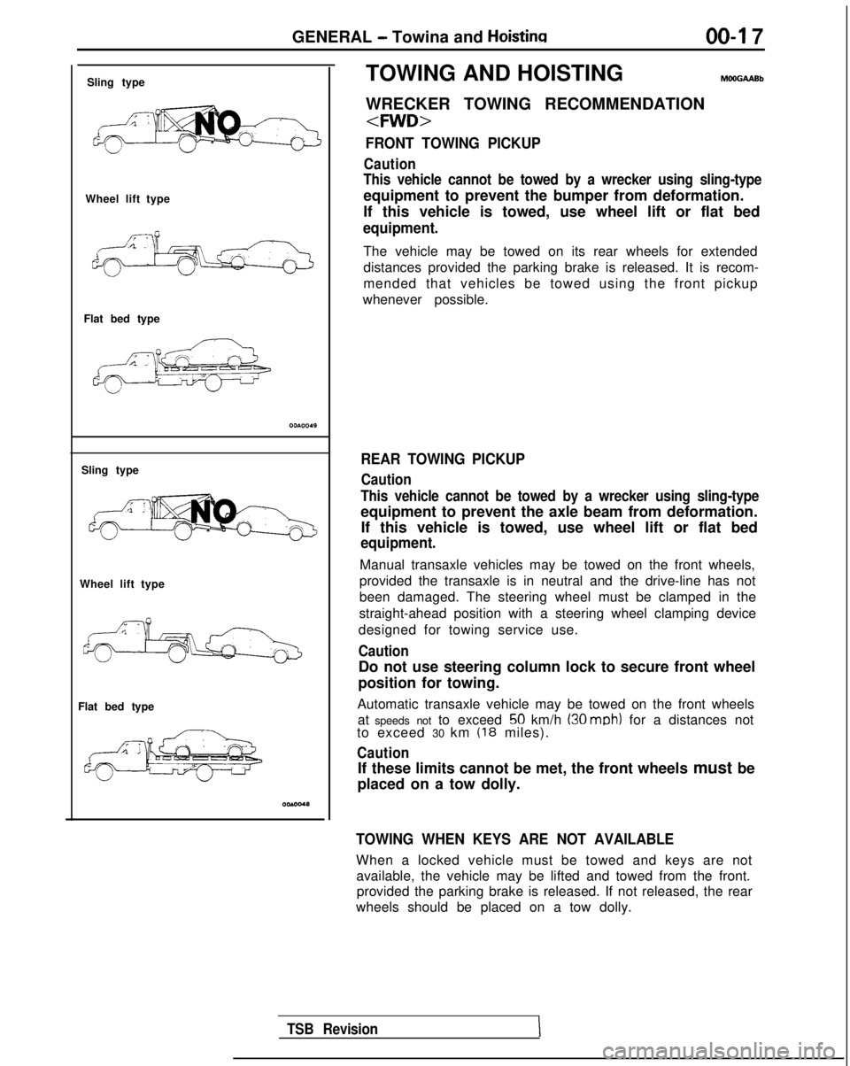
Sling type
Wheel lift type
Flat bed type
Sling type
Wheel lift type
Flat bed type TOWING AND HOISTING
WRECKER TOWING RECOMMENDATION
FRONT TOWING PICKUP
Caution
This vehicle cannot be towed by a wrecker using sling-type
equipment to prevent the bumper from deformation.
If this vehicle is towed, use wheel lift or flat bed
equipment.
The vehicle may be towed on its rear wheels for extended
distances provided the parking brake is released. It is recom-
mended that vehicles be towed using the front pickup
whenever possible.
REAR TOWING PICKUP
Caution
This vehicle cannot be towed by a wrecker using sling-type
equipment to prevent the axle beam from deformation. If this vehicle is towed, use wheel lift or flat bed
equipment.
Manual transaxle vehicles may be towed on the front wheels,
provided the transaxle is in neutral and the drive-line has not
been damaged. The steering wheel must be clamped in the
straight-ahead position with a steering wheel clamping device
designed for towing service use.
Caution
Do not use steering column lock to secure front wheel
position for towing.
Automatic transaxle vehicle may be towed on the front wheels at speeds not to exceed
50 km/h (30 mob) for a distances not
to exceed 30 km (18 miles).
Caution
If these limits cannot be met, the front wheels must be
placed on a tow dolly.
TOWING WHEN KEYS ARE NOT AVAILABLE
When a locked vehicle must be towed and keys are not available, the vehicle may be lifted and towed from the front.provided the parking brake is released. If not released, the rear
wheels should be placed on a tow dolly.
TSB Revision
Page 20 of 1273
00-l 8GENERAL - Towing and Hoisting
SAFETY PRECAUTIONS
The following precautions should be taken when towing thevehicle.
1.DO NOT LIFT OR TOW THE VEHICLE BY ATTACHING TO
OR WRAPPING AROUND THE BUMPER.
2. Any loose or protruding parts of damaged vehicle such as hoods, doors, fenders, trim, etc., should be secured prior to
moving the vehicle.
3.Operator should refrain from going under a vehicle while it
is lifted by the towing equipment, unless the vehicle in
adequately supported by satefy stands.
4. Never allow passengers to ride in a towed vehicle. 5. State and local rules and regulations must be followed when towing a vehicle.
Refer to the section “Special Handling Instructions for AWD
Models”.
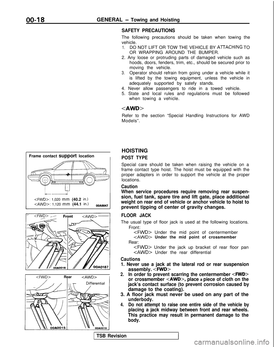
Frame contact support location
I
HOISTING
POST TYPE
Special care should be taken when raising the vehicle on a
frame contact type hoist. The hoist must be equipped with the
proper adapters in order to support the vehicle at the proper
locations.
Caution
When service procedures require removing rear suspen-
sion, fuel tank, spare tire and lift gate, place additional
weight on rear end of vehicle or anchor vehicle to hoist to
prevent tipping of center of gravity changes.
FLOOR JACK
The usual type of floor jack is used at the following locations.
Front:
tAWD> Under the mid point of crossmember
Rear:
Cautions
1. Never use a jack at the lateral rod or rear suspension
assembly.
2.In order to prevent scarring the centermember
or crossmember
place a piece of cloth on the
jack’s contact surface (to prevent corrosion caused by
damage to the coating).
3. A floor jack must never be used on any part of the
underbody.
4.Do not attempt to raise one entire side of the vehicle by
placing a jack midway between front and rear wheels.
This practice may result in permanent damage to the
body.
TSB RevisionI
Page 23 of 1273
GENERAL - Special Handling Instructions for AWD Models00-21
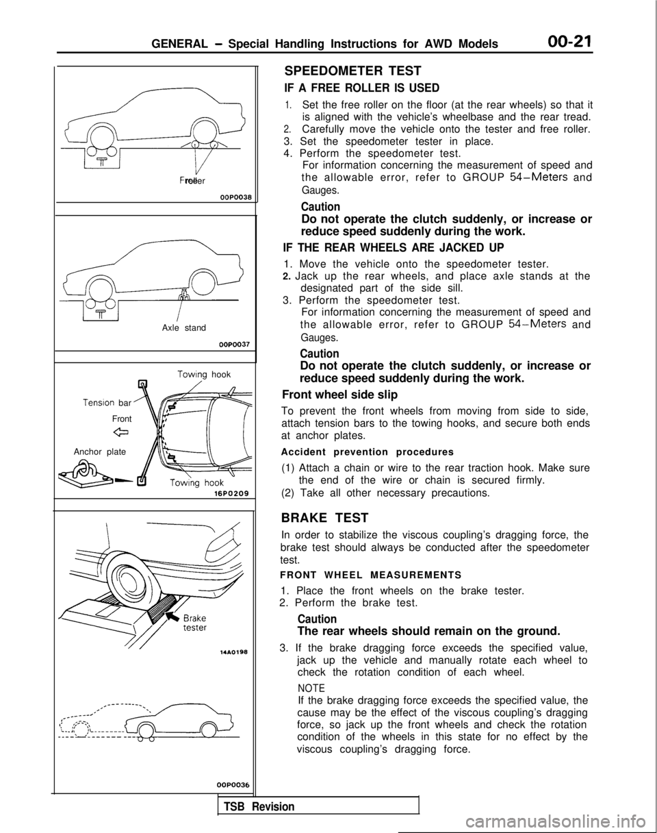
Free roller
OOPO038
Axle stand
OOPOO37
Towino hook
Tenslon
bar
Front
eJ
Anchor plate
&-16PO209 14AO198
OOP003E
SPEEDOMETER TEST
IF A FREE ROLLER IS USED
1.Set the free roller on the floor (at the rear wheels) so that it
is aligned with the vehicle’s wheelbase and the rear tread.
2.Carefully move the vehicle onto the tester and free roller.
3. Set the speedometer tester in place.
4. Perform the speedometer test. For information concerning the measurement of speed and
the allowable error, refer to GROUP
54-Meters and
Gauges.
Caution
Do not operate the clutch suddenly, or increase or
reduce speed suddenly during the work.
IF THE REAR WHEELS ARE JACKED UP
1. Move the vehicle onto the speedometer tester.
2. Jack up the rear wheels, and place axle stands at the designated part of the side sill.
3. Perform the speedometer test. For information concerning the measurement of speed and
the allowable error, refer to GROUP
54-Meters and
Gauges.
Caution
Do not operate the clutch suddenly, or increase or
reduce speed suddenly during the work.
Front wheel side slip
To prevent the front wheels from moving from side to side, attach tension bars to the towing hooks, and secure both ends
at anchor plates.
Accident prevention procedures (1) Attach a chain or wire to the rear traction hook. Make sure the end of the wire or chain is secured firmly.
(2) Take all other necessary precautions.
BRAKE TEST In order to stabilize the viscous coupling’s dragging force, the
brake test should always be conducted after the speedometer
test.
FRONT WHEEL MEASUREMENTS
1. Place the front wheels on the brake tester.
2. Perform the brake test.
Caution
The rear wheels should remain on the ground.
3. If the brake dragging force exceeds the specified value, jack up the vehicle and manually rotate each wheel tocheck the rotation condition of each wheel.
NOTE
If the brake dragging force exceeds the specified value, the
cause may be the effect of the viscous coupling’s dragging
force, so jack up the front wheels and check the rotation condition of the wheels in this state for no effect by the
viscous coupling’s dragging force.
,
TSB Revision
Page 33 of 1273
GENERAL - Master Troubleshooting
00-31
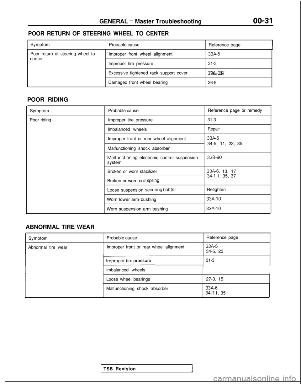
POOR RETURN OF STEERING WHEEL TO CENTER
Symptom
Probable cause Reference page
’Poor return of steering wheel to
Improper front wheel alignment33A-5center
Improper tire pressure31-3
Excessive tightened rack support cover 37A-35, 36, 37
Damaged front wheel bearing
26-9
POOR RIDING
Symptom
Poor riding Probable cause
Reference page or remedy
Improper tire pressure
31-3
lmbalanced wheelsRepair
Improper front or rear wheel alignment33A-5
34-5, 11, 23, 35
Malfunctioning shock absorber Malfunctioning
electronic control suspension
33B-90system
Broken or worn stabilizer
33A-6. 13, 1734-l 1, 35, 37
Broken or worn coil spri#ng
Loose suspension secuiring bolt(s)
Retighten
Worn lower arm bushing
33A-10
Worn suspension arm bushing 33A-IO
TSB Revision
ABNORMAL TIRE WEAR
Symptom
Abnormal tire wear Probable cause
Improper front or rear wheel alignment Reference page
33A-534-5, 23
131-3
lmbalanced wheelsII
Loose wheel bearings
27-3, 15
Malfunctioning shock absorber
33A-634-l 1, 35
Page 46 of 1273
GENERAL -Maintenance Service
(1O)Star-t engine and allow to idle for at least two minutes.
Then, with parking brake on, move selector
fever
momentarily to each position, ending in “N” Neutral
position.
(11)Add sufficient ATF to bring fluid level to lower mark.
Recheck fluid level after transaxle is at normal Operating
temperature. Fluid level should be between upper and lower marks of
“HOT” range, Insert dipstick fully to prevent dirt from
entering transaxle.
OOA0051
11 .ENGINE
COOLANT (Change)MOOSEEAC
Check the cooling system parts, such as radiator, heater,
and oil cooler hoses, thermostat and connections for
leakage and damage.
CHANGE COOLANT
1. Remove the radiator cap.
2. Loosen the drain plug to drain the coolant.
3. Drain the coolant from the reserve tank.
4. After draining the coolant, tighten the drain plug securely.
5.Supply the coolant into the radiator until it is filled up to
its filler neck.
6. Supply the coolant into the reserve tank.
7. After warming the engine until the thermostat opens, remove the radiator cap and check the coolant level.
8.Supply the coolant into the radiator until it is filled up to
its filler neck, and install the radiator cap securely.
9.Fill the reserve tank with coolant up to the “FULL” line.
14K512
1 12.DISC BRAKE PADS (Inspect for wear) MWSBFA
Check for fluid contamination and wear. Replace complete
set of pads if defective.
Caution
The pads for the right and left wheels should be
reDlaced at the same time. Never “split” or intermix
brkke pad sets.
All four pads must be replace as a complete set.
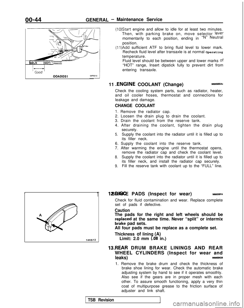
Thickness of lining (A)
Limit: 2.0 mm (.08 in.)
13.REAR DRUM BRAKE LININGS AND REAR
WHEEL CYLINDERS (Inspect for wear and
leaks)MOOSBGB
1. Remove the brake drum and check the thickness of brake shoe lining for wear. Check the automatic brake
adjusting system by hand to see if it operates smoothly.
Also see if the gears are in proper mesh with each
other. To assure smooth functioning, apply a very thin
coat of multipurpose grease to the friction surface of
adjuster and link shaft.
TSB Revision1
Page 90 of 1273
II-40ENGINE
OlRO372
1(3) Move tensioner fully toward water pump and tempo-rarily secure tensioner.
Timing mark Timing mark
(on cylinder head)
Timing mark
“1(on front case) ,A.
Timing mark6EN063
3ENOO5
Tensiorof belt-I sid
e
Tension side of belt
6EN0065
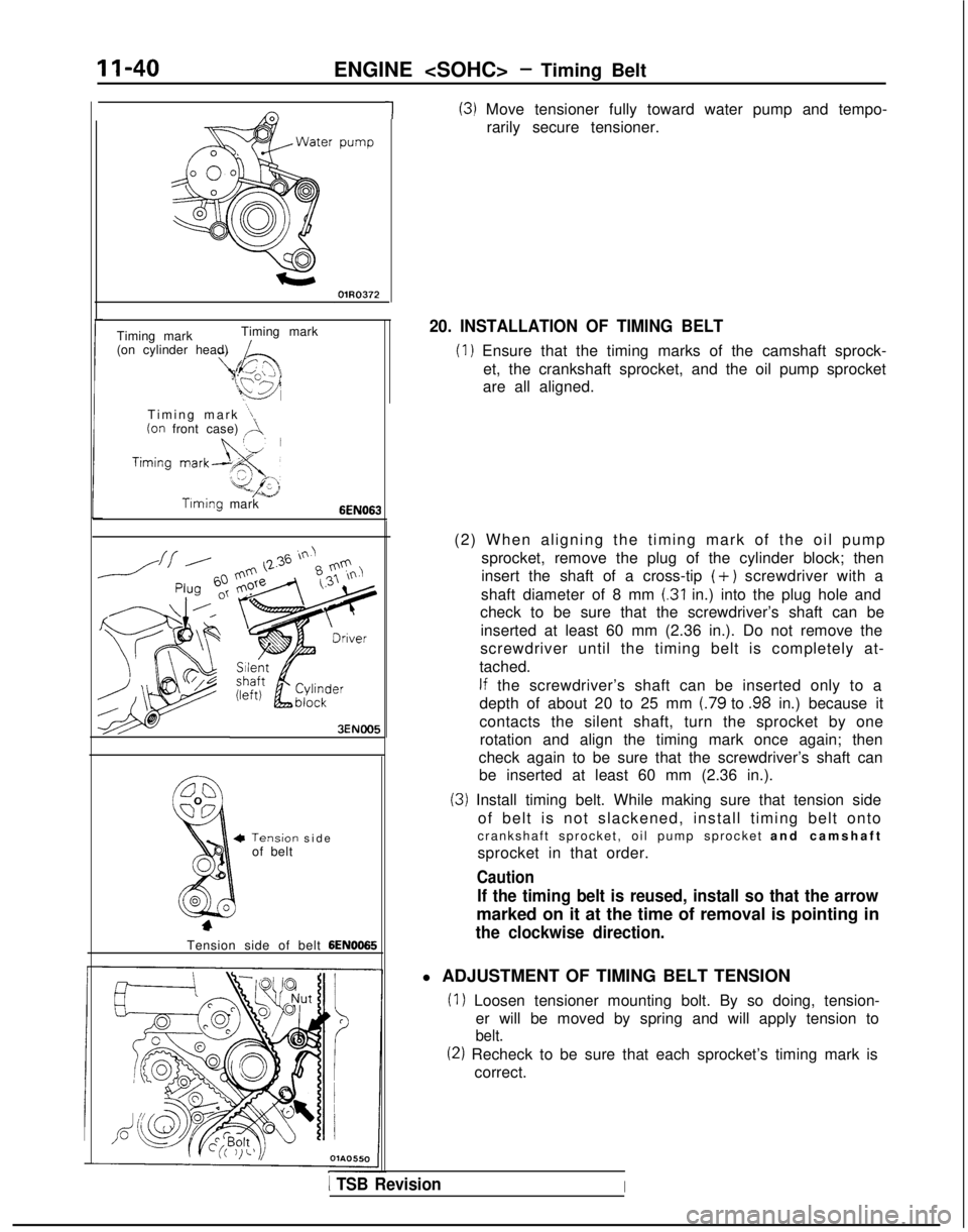
20. INSTALLATION OF TIMING BELT
(1) Ensure that the timing marks of the camshaft sprock- et, the crankshaft sprocket, and the oil pump sprocket
are all aligned.
(2) When aligning the timing mark of the oil pump sprocket, remove the plug of the cylinder block; then
insert the shaft of a cross-tip
(+) screwdriver with a
shaft diameter of 8 mm
(.31 in.) into the plug hole and
check to be sure that the screwdriver’s shaft can be
inserted at least 60 mm (2.36 in.). Do not remove the
screwdriver until the timing belt is completely at-
tached.
If the screwdriver’s shaft can be inserted only to a
depth of about 20 to 25 mm
(.79 to .98 in.) because it
contacts the silent shaft, turn the sprocket by one rotation and align the timing mark once again; then
check again to be sure that the screwdriver’s shaft can be inserted at least 60 mm (2.36 in.).
(3) Install timing belt. While making sure that tension side
of belt is not slackened, install timing belt onto
crankshaft sprocket, oil pump sprocket and camshaf
t
sprocket in that order.
Caution
If the timing belt is reused, install so that the arrow
marked on it at the time of removal is pointing in
the clockwise direction.
l ADJUSTMENT OF TIMING BELT TENSION
(1) Loosen tensioner mounting bolt. By so doing, tension- er will be moved by spring and will apply tension to
belt.
(2) Recheck to be sure that each sprocket’s timing mark iscorrect.
1 TSB RevisionI
Page 101 of 1273
ENGINE
r
L Camshaft sprocket
Idler
pulley
/Oil pumpOlA0668
sprocket
6EN0175
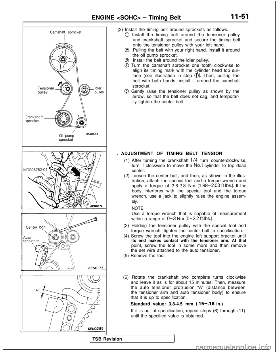
(3) Install the timing belt around sprockets as follows.
@ Install the timing belt around the tensioner pulley
and crankshaft sprocket and secure the timing belt
onto the tensioner pulley with your left hand.
@Pulling the belt with your right hand, install it around
the oil pump sprocket.
@Install the belt around the idler pulley.
@ Turn the camshaft sprocket one tooth clockwise to align its timing mark with the cylinder head top sur-
face (see illustration in step
0). Then, pulling the
belt with both hands, install it around the camshaft
sprocket.
@ Gently raise the tensioner pulley as shown by the arrow, so that the belt does not sag, and temporar-
ily tighten the center bolt.
. ADJUSTMENT OF TIMING BELT TENSION (1) After turning the crankshaft
l/4 turn counterclockwise,
turn it clockwise to move the
No.1 cylinder to top dead
center.
(2) Loosen the center bolt, and then, as shown in the illus- tration, attach the special tool and a torque wrench and
apply a torque of 2.6-2.8 Nm
(1.88-2.03 ft.lbs.). If the
body interferes with the special tool and the torque
wrench, use a jack to slightly raise the engine assem-
bly.
NOTE
Use a torque wrench that is capable of measurement
within a range of
O-3 Nm (O-2.2
ftlbs.)
(3) Holding the tensioner pulley with the special tool and
torque wrench, tighten the center bolt to specification.
(4) Screw the tool into the engine left support bracket until its end makes contact with the tensioner arm. At that
point, screw the tool in some more and then remove
the set wire attached to the auto tensioner.
(5) Remove the tool.
(6) Rotate the crankshaft two complete turns clockwise and leave it as is for about 15 minutes. Then, measure
the auto tensioner protrusion “A” (distance between
the tensioner arm and auto tensioner body) to ensure
that it is up to specification.
Standard value: 3.8-4.5 mm
(.15-.18 in.)
If it is out of specification, repeat steps (6) through (11)
until the specified value is obtained.
TSB Revision
I
Page 158 of 1273
13-16
FUEL SYSTEM
FAILSAFE/BACK-UP FUNCTIONS LIST
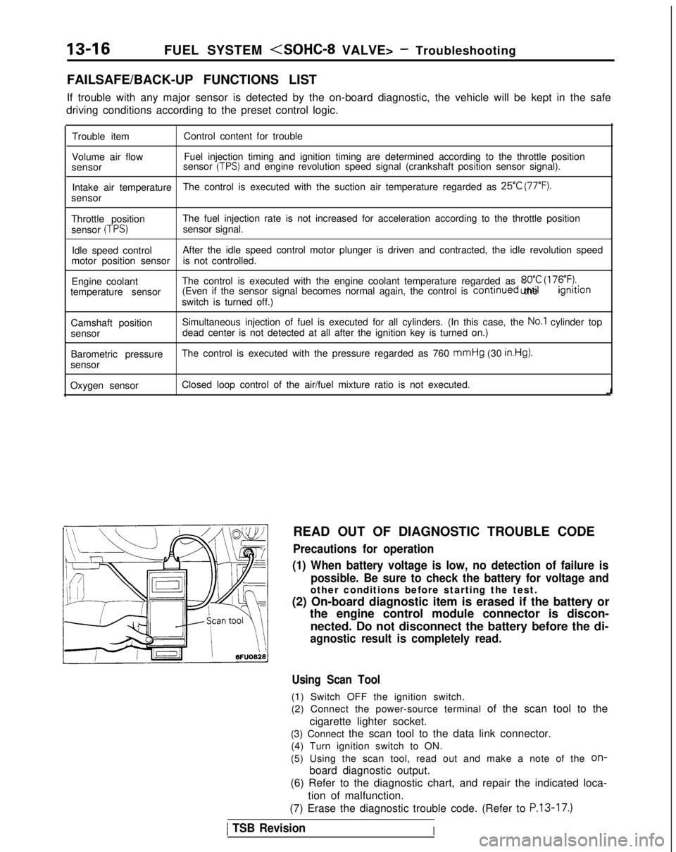
If trouble with any major sensor is detected by the on-board diagnostic,\
the vehicle will be kept in the safe
driving conditions according to the preset control logic.
Trouble item Control content for trouble
Volume air flow Fuel injection timing and ignition timing are determined according to th\
e throttle position
sensor sensor
(TPS) and engine revolution speed signal (crankshaft position sensor signal)\
.
Intake air temperature The control is executed with the suction air temperature regarded as
25°C (77°F).
sensor
Throttle position The fuel injection rate is not increased for acceleration according to t\
he throttle position
sensor
(TPS)sensor signal.
Idle speed control After the idle speed control motor plunger is driven and contracted, the\
idle revolution speed
motor position sensor is not controlled.
Engine coolant The control is executed with the engine coolant temperature regarded as \
8OO.C (176°F).temperature sensor (Even if the sensor signal becomes normal again, the control is continued
until the ignltlon
switch is turned off.)
Camshaft position Simultaneous injection of fuel is executed for all cylinders. (In this \
case, the
No.1 cylinder top
sensor dead center is not detected at all after the ignition key is turned on.)\
Barometric pressure The control is executed with the pressure regarded as 760 mmHg
(30
in.Hg).
sensor
Oxygen sensor Closed loop control of the air/fuel mixture ratio is not executed.
i
READ OUT OF DIAGNOSTIC TROUBLE CODE
Precautions for operation
(1) When battery voltage is low, no detection of failure is possible. Be sure to check the battery for voltage and
other conditions before starting the test.
(2) On-board diagnostic item is erased if the battery or the engine control module connector is discon-
nected. Do not disconnect the battery before the di-
agnostic result is completely read.
Using Scan Tool
(1) Switch OFF the ignition switch.
(2) Connect the power-source terminal of the scan tool to the
cigarette lighter socket.
(3) Connect the scan tool to the data link connector. (4) Turn ignition switch to ON.
(5) Using the scan tool, read out and make a note of the
on-
board diagnostic output.
(6) Refer to the diagnostic chart, and repair the indicated loca-
tion of malfunction.
(7) Erase the diagnostic trouble code. (Refer to
P.13-17.)
1 TSB RevisionI
Page 176 of 1273
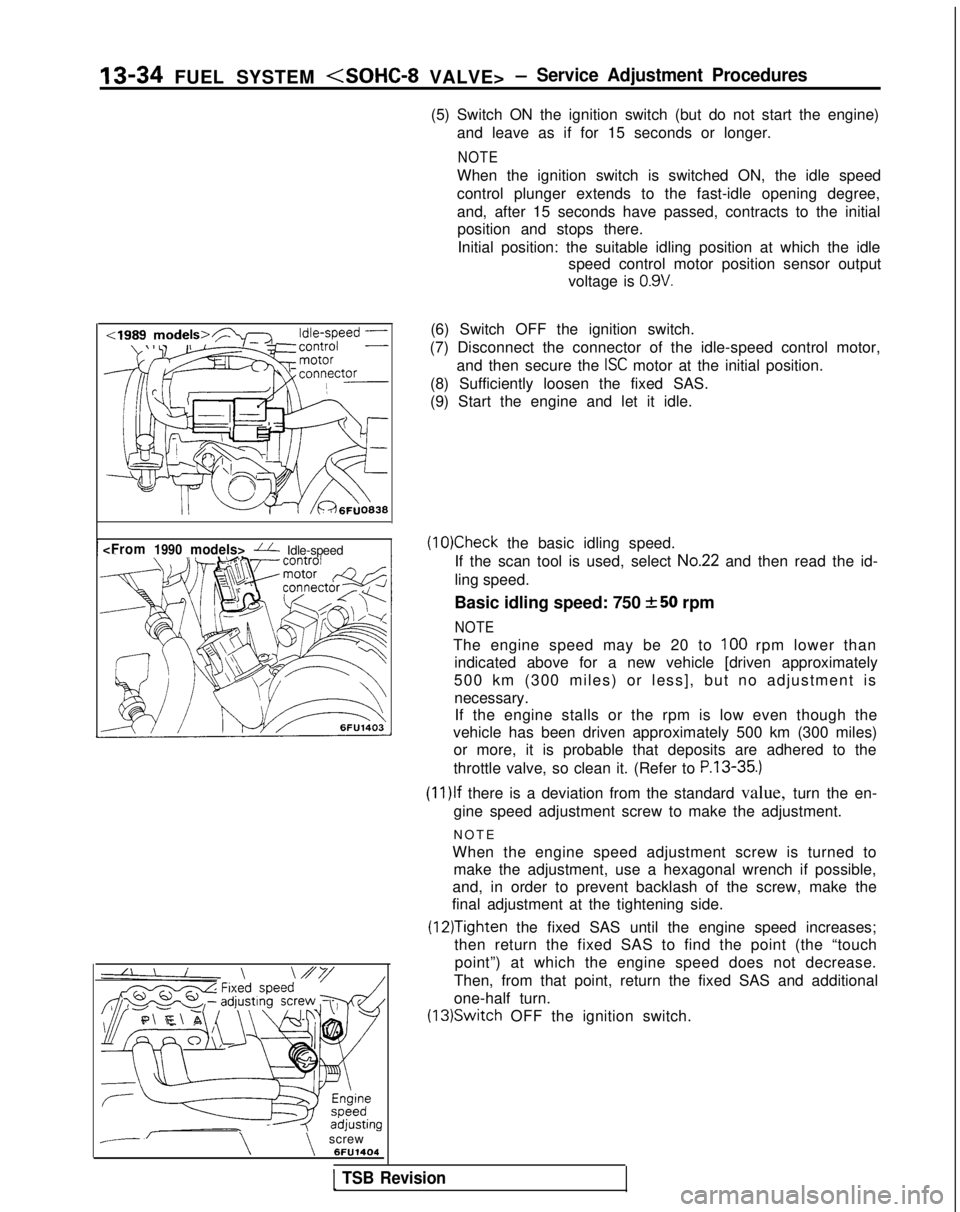
13-34 FUEL SYSTEM
(5) Switch ON the ignition switch (but do not start the engine)and leave as if for 15 seconds or longer.
NOTE
When the ignition switch is switched ON, the idle speed
control plunger extends to the fast-idle opening degree,
and, after 15 seconds have passed, contracts to the initialposition and stops there.
Initial position: the suitable idling position at which the idle speed control motor position sensor output
voltage is
0.9V.
--\\screw 6FU1404(6) Switch OFF the ignition switch.
(7) Disconnect the connector of the idle-speed control motor, and then secure the
ISC motor at the initial position.
(8) Sufficiently loosen the fixed SAS.
(9) Start the engine and let it idle.
(10)Check the basic idling speed.
If the scan tool is used, select
No.22 and then read the id-
ling speed.
Basic idling speed: 750
+-50 rpm
NOTE
The engine speed may be 20 to 100 rpm lower than
indicated above for a new vehicle [driven approximately
500 km (300 miles) or less], but no adjustment is necessary.If the engine stalls or the rpm is low even though the
vehicle has been driven approximately 500 km (300 miles) or more, it is probable that deposits are adhered to the
throttle valve, so clean it. (Refer to
P.13-35.)
(1l)lf there is a deviation from the standard value, turn the en-
gine speed adjustment screw to make the adjustment.
NOT
E
When the engine speed adjustment screw is turned to make the adjustment, use a hexagonal wrench if possible,
and, in order to prevent backlash of the screw, make the
final adjustment at the tightening side.
(12)Tighten the fixed SAS until the engine speed increases;
then return the fixed SAS to find the point (the “touch
point”) at which the engine speed does not decrease.
Then, from that point, return the fixed SAS and additional
one-half turn. (13)Switch
OFF the ignition switch.
1 TSB Revision
Page 179 of 1273
FUEL SYSTEM (SOHC-8 VALVE> -Service Adjustment Procedures 13-37
MO-L
6FU1405
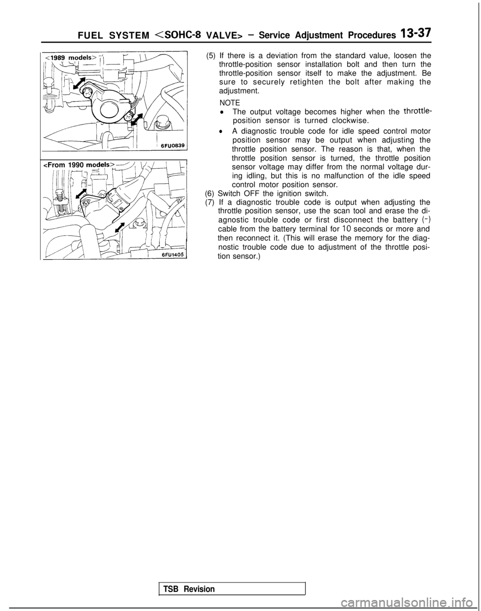
(5) If there is a deviation from the standard value, loosen the
throttle-position sensor installation bolt and then turn the
throttle-position sensor itself to make the adjustment. Be
sure to securely retighten the bolt after making the
adjustment.
NOTE
lThe output voltage becomes higher when the throttle-
position sensor is turned clockwise.
lA diagnostic trouble code for idle speed control motor position sensor may be output when adjusting the
throttle position sensor. The reason is that, when the
throttle position sensor is turned, the throttle position sensor voltage may differ from the normal voltage dur-
ing idling, but this is no malfunction of the idle speed
control motor position sensor.
(6) Switch OFF the ignition switch. (7) If a diagnostic trouble code is output when adjusting the throttle position sensor, use the scan tool and erase the di-
agnostic trouble code or first disconnect the battery (-)
cable from the battery terminal for IO
seconds or more and
then reconnect it. (This will erase the memory for the diag- nostic trouble code due to adjustment of the throttle posi-
tion sensor.)
TSB Revision