boot MITSUBISHI GALANT 1989 Service User Guide
[x] Cancel search | Manufacturer: MITSUBISHI, Model Year: 1989, Model line: GALANT, Model: MITSUBISHI GALANT 1989Pages: 1273, PDF Size: 37.62 MB
Page 825 of 1273
PROPELLER SHAFT - Propeller Shaft25-11
Washer
Tape
Inner raceI Rnll
Recessed endof inner race
Chamfered end
fitting the packing
SERVICE POINTS OF REASSEMBLYMZ9GHAQ
19. INSTALLATION OF WASHER/18. LOBRO JOINT BOOT
OR D.O.J. BOOT/17. BOOT BAND/lG.
RUBBER
PACKING/15. LOBRO JOINT ASSEMBLY OR D.O.J.
ASSEMBLY / 14. SNAP RING
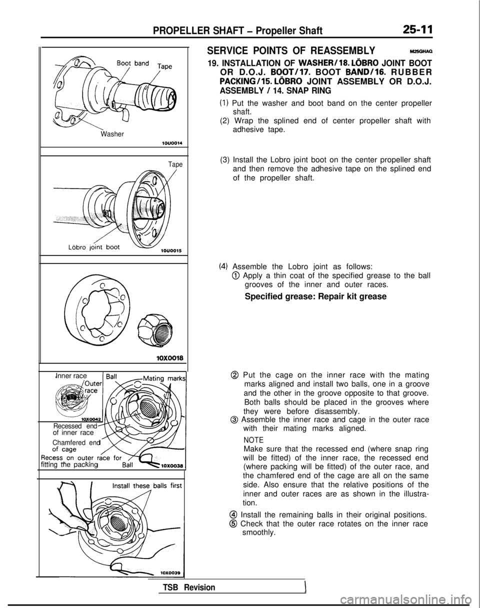
(1) Put the washer and boot band on the center propeller
shaft.
(2) Wrap the splined end of center propeller shaft with
adhesive tape.
(3) Install the Lobro joint boot on the center propeller shaft and then remove the adhesive tape on the splined end
of the propeller shaft.
(4) Assemble the Lobro joint as follows:
@ Apply a thin coat of the specified grease to the ball grooves of the inner and outer races.
Specified grease: Repair kit grease
@ Put the cage on the inner race with the mating marks aligned and install two balls, one in a groove
and the other in the groove opposite to that groove. Both balls should be placed in the grooves where
they were before disassembly.
@I Assemble the inner race and cage in the outer race with their mating marks aligned.
NOTE
Make sure that the recessed end (where snap ring
will be fitted) of the inner race, the recessed end (where packing will be fitted) of the outer race, and
the chamfered end of the cage are all on the same
side. Also ensure that the relative positions of the
inner and outer races are as shown in the illustra-
tion.
@I Install the remaining balls in their original positions.
@ Check that the outer race rotates on the inner race smoothly.
TSB RevisionI
Page 826 of 1273
25-12PROPELLER SHAFT - Propeller Shaft
10x0040
Rubberking
Mounting bolts
LBbro joint bootIlOUOO16 1
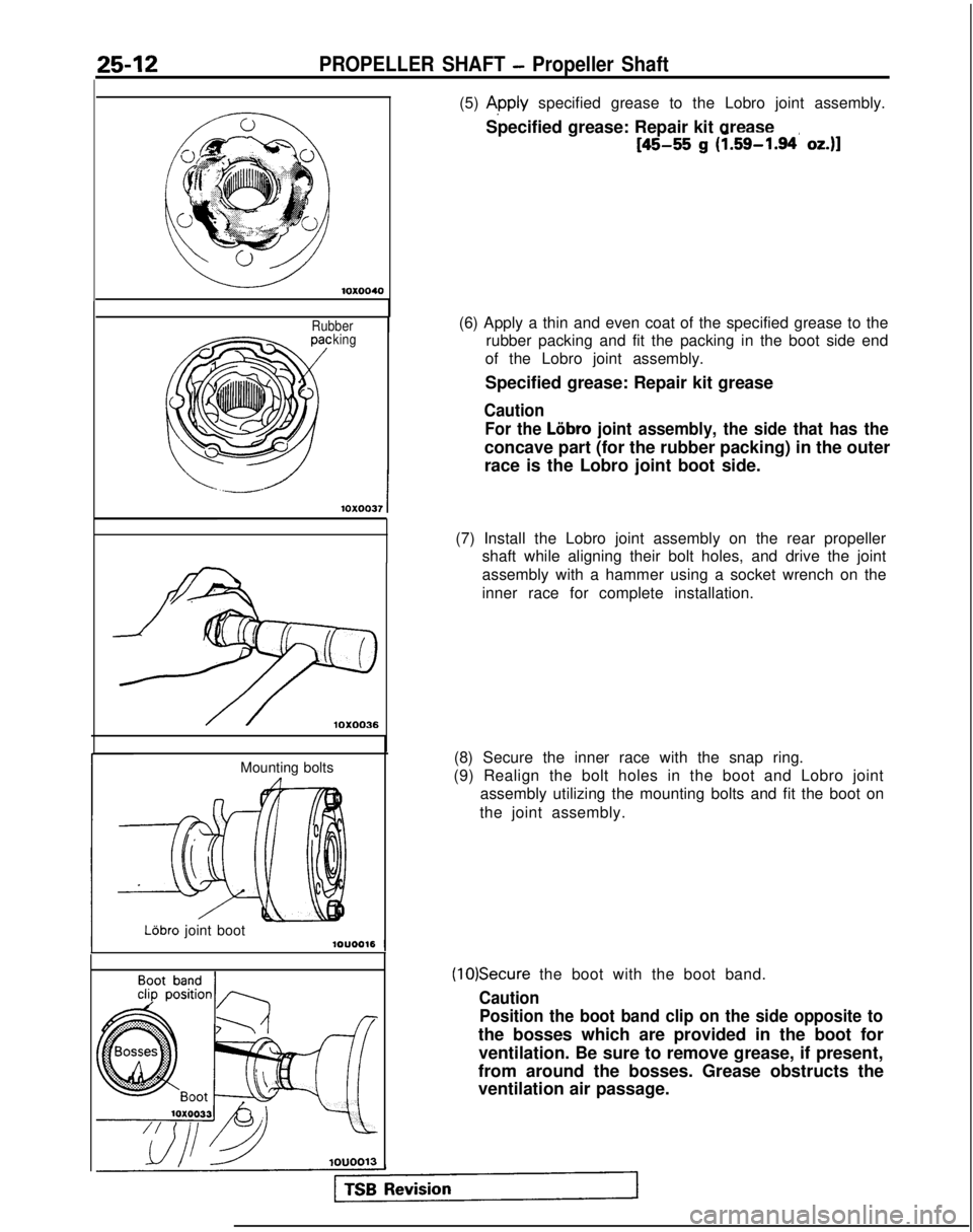
(5) Apply specified grease to the Lobro joint assembly.
Specified grease: Repair kit grease
[45-55 g (1.59-1.94 oz.)]
(6) Apply a thin and even coat of the specified grease to the rubber packing and fit the packing in the boot side end
of the Lobro joint assembly.
Specified grease: Repair kit grease
Caution
For the
Lobro joint assembly, the side that has the
concave part (for the rubber packing) in the outer
race is the Lobro joint boot side.
(7) Install the Lobro joint assembly on the rear propeller shaft while aligning their bolt holes, and drive the joint
assembly with a hammer using a socket wrench on the
inner race for complete installation.
(8) Secure the inner race with the snap ring.
(9) Realign the bolt holes in the boot and Lobro joint assembly utilizing the mounting bolts and fit the boot on
the joint assembly.
(10)Secure the boot with the boot band.
Caution Position the boot band clip on the side opposite to
the bosses which are provided in the boot for
ventilation. Be sure to remove grease, if present,
from around the bosses. Grease obstructs the
ventilation air passage.
Page 827 of 1273
Check that the Lobro joint assembly moves smoothly.
-41ouoo17
Washer1ouoo14
Tape
D.O.J. boot
-
c @
@
0
2
c
0 @\
a@
llAO357
10x0040
I
19. INSTALLATION OF WA")
PROPELLER SHAFT - Propeller Shaft_25-13
(11 )Check that the Lobro joint assembly moves smoothly.
-41ouoo17
Washer1ouoo14
Tape
D.O.J. boot
-
c @
@
0
2
c
0 @\
a@
llAO357
10x0040
I
19. INSTALLATION OF WASHER/18.
D.O.J. JOINT BOOT/
17. BOOT BAND/lG. RUBBER PACKING/15
D.O.J.
ASSEMBLY
/14. SNAP RING
(1) Put the washer and boot band on
t.he center propeller
shaft.
(2) Wrap the splined end of center propeller shaft with adhesive tape.
(3) Install the D.O.J. boot on the center propeller shaft andthen remove the adhesive tape on the splined end of
the propeller shaft.
(4) Assemble the D.O.J. as follows:
@ Apply a th’tn coat of the specified grease to the ball
grooves of the inner and outer races.
Specified grease: Repair kit grease
0 Assemble the inner race and cage in the outer race with their mating marks aligned.
@ Install the circlip.
(5) Apply specified grease to the D.O.J. assembly. Specified grease: Repair kit
grease
[105-115 g (3.7-4.0 oz.)1
1 TSB RevisionI
Page 828 of 1273
25-14PROPELLER SHAFT - Propeller Shaft
king
Mounting bolts
D.O.J. bootlOUOO16
Boot bandcl@ position fi
1ouoo13
Rubber mountI
Dust seal
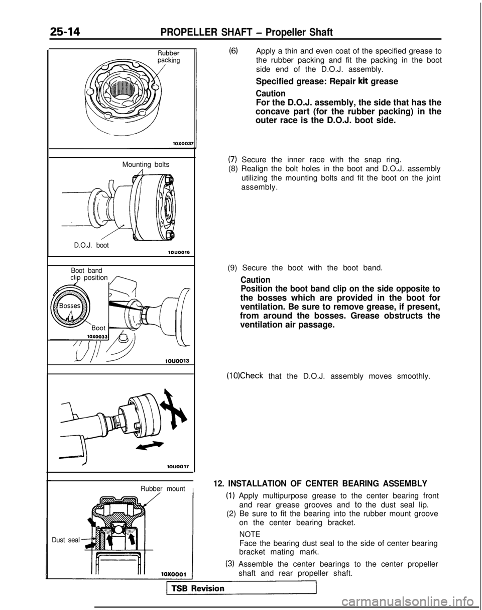
(6)Apply a thin and even coat of the specified grease tothe rubber packing and fit the packing in the boot
side end of the D.O.J. assembly.
Specified grease: Repair
kit grease
Caution
For the D.O.J. assembly, the side that has the
concave part (for the rubber packing) in the
outer race is the D.O.J. boot side.
(7) Secure the inner race with the snap ring.
(8) Realign the bolt holes in the boot and D.O.J. assembly
utilizing the mounting bolts and fit the boot on the joint
assembly.
(9) Secure the boot with the boot band.
Caution Position the boot band clip on the side opposite to
the bosses which are provided in the boot for
ventilation. Be sure to remove grease, if present,
from around the bosses. Grease obstructs the ventilation air passage.
(10)Check that the D.O.J. assembly moves smoothly.
12. INSTALLATION OF CENTER BEARING ASSEMBLY
(1) Apply multipurpose grease to the center bearing front
and rear grease grooves and to the dust seal lip.
(2) Be sure to fit the bearing into the rubber mount groove
on the center bearing bracket.
NOTE
Face the bearing dust seal to the side of center bearing
bracket mating mark.
(3) Assemble the center bearings to the center propeller
shaft and rear propeller shaft.
Page 829 of 1273
PROPELLER SHAFT - Propeller Shaft25-15 ?
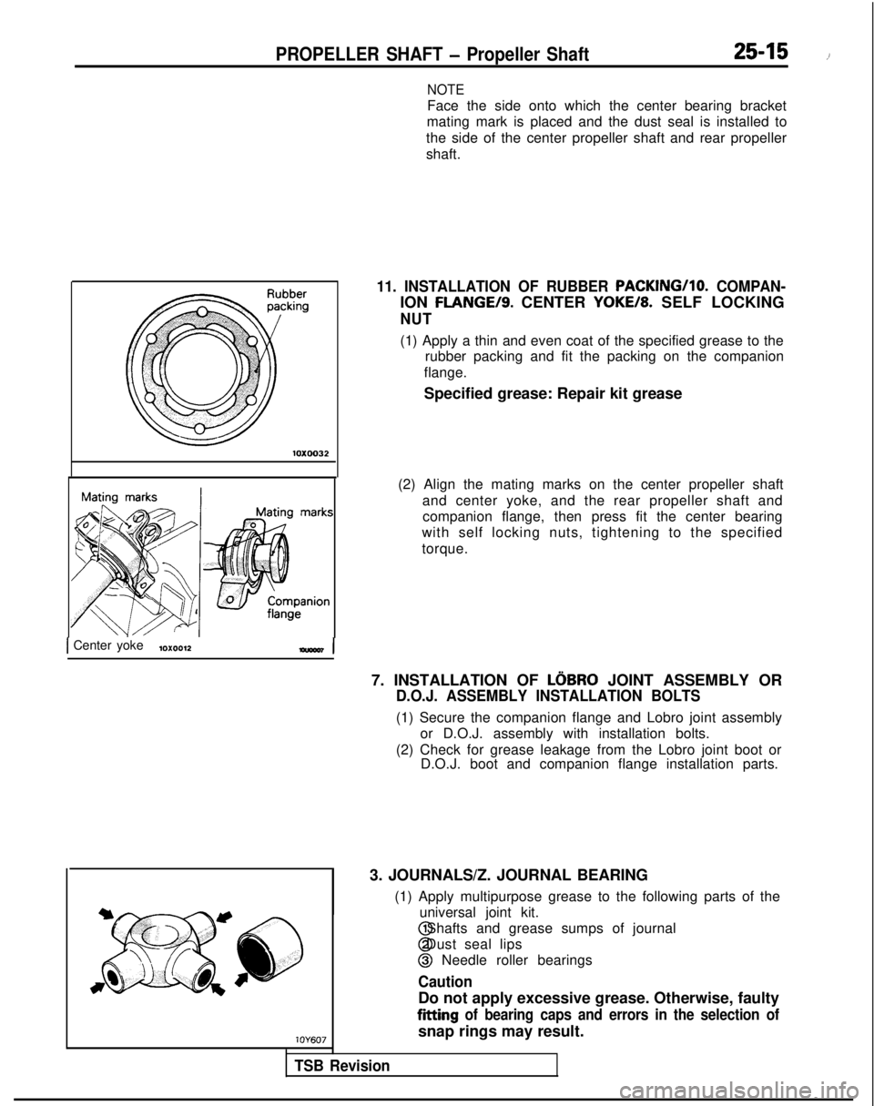
NOTE
Face the side onto which the center bearing bracket
mating mark is placed and the dust seal is installed to
the side of the center propeller shaft and rear propeller
shaft. 10X0032
1 Center yoke10x0012-I
11. INSTALLATION OF RUBBER PACKING/lo.
COMPAN-
ION FLANGE/S. CENTER YOKE/8. SELF LOCKING
NUT
(1) Apply a thin and even coat of the specified grease to the
rubber packing and fit the packing on the companion
flange.
Specified grease: Repair kit grease
(2) Align the mating marks on the center propeller shaft and center yoke, and the rear propeller shaft andcompanion flange, then press fit the center bearing
with self locking nuts, tightening to the specified
torque.
7. INSTALLATION OF
LOBRO JOINT ASSEMBLY OR
D.O.J. ASSEMBLY INSTALLATION BOLTS
(1) Secure the companion flange and Lobro joint assembly or D.O.J. assembly with installation bolts.
(2) Check for grease leakage from the Lobro joint boot or D.O.J. boot and companion flange installation parts.
3. JOURNALS/Z. JOURNAL BEARING
TSB Revision lOY607(1) Apply multipurpose grease to the following parts of the
universal joint kit. @ Shafts and grease sumps of journal
@ Dust seal lips
@ Needle roller bearings
Caution
Do not apply excessive grease. Otherwise, faulty
fitting of bearing caps and errors in the selection of
snap rings may result.
Page 832 of 1273
26-2
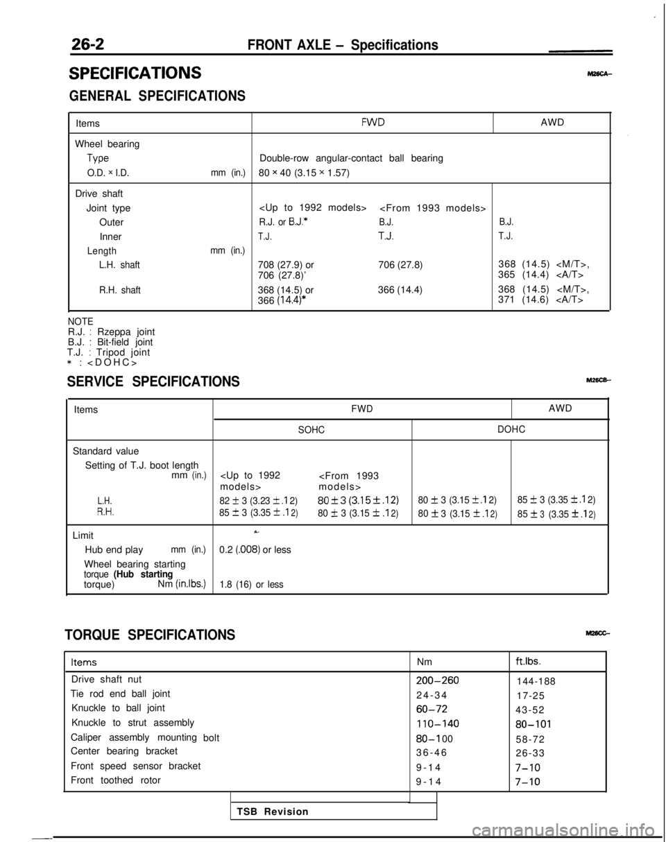
SPECIFICATIONS
FRONT AXLE - Specifications
GENERAL SPECIFICATIONS
Items
Wheel bearing Type
O.D. x I.D.
Drive shaft
Joint type Outer
Inner
Length L.H. shaft
R.H. shaft
FWDAWD
Double-row angular-contact ball bearing
mm (in.)80 x 40 (3.15 x 1.57)
R.J. or B.J.*B.J. B.J.
T.J.T.J.T.J.
mm (in.)
708 (27.9) or
706 (27.8)368 (14.5)
706 (27.8)’ 365 (14.4)
368 (14.5) or 366 (14.4)368 (14.5)
366
(14.4)*371 (14.6)
NOTER.J. : Rzeppa joint
B.J. : Bit-field joint
T.J. : Tripod joint *:
>
SERVICE SPECIFICATIONS
ItemsFWDAWD
SOHC
DOHC
Standard value
Setting of T.J. boot length mm
(in.)
L.H.82 + 3 (3.23 k .I 2)80f3 (3.15f.12)80 + 3 (3.15 f .I 2)
85 f 3 (3.35 k .I 2)
R.H.85 III 3 (3.35 +
.I2)80 IL 3 (3.15 f.I2)80f3
(3.15f .I2)85f3(3.3531
.I2)
LimitX.
Hub end playmm (in.)0.2 (.008) or less
Wheel bearing starting
torque (Hub startingtorque) Nm (inlbs.)1.8 (16) or less
TORQUE SPECIFICATIONS
ItemsNmftlbs.
Drive shaft nut200-260144-188
Tie rod end ball joint 24-3
4
17-25
Knuckle to ball joint
60-7243-52
Knuckle to strut assembly
110-14080-101
Caliper assembly mounting bolt80-I 0058-72
Center bearing bracket 36-4
6
26-33
Front speed sensor bracket 9-14
7-10
Front toothed rotor9-1
4
7-10
TSB Revision
-_
Page 833 of 1273
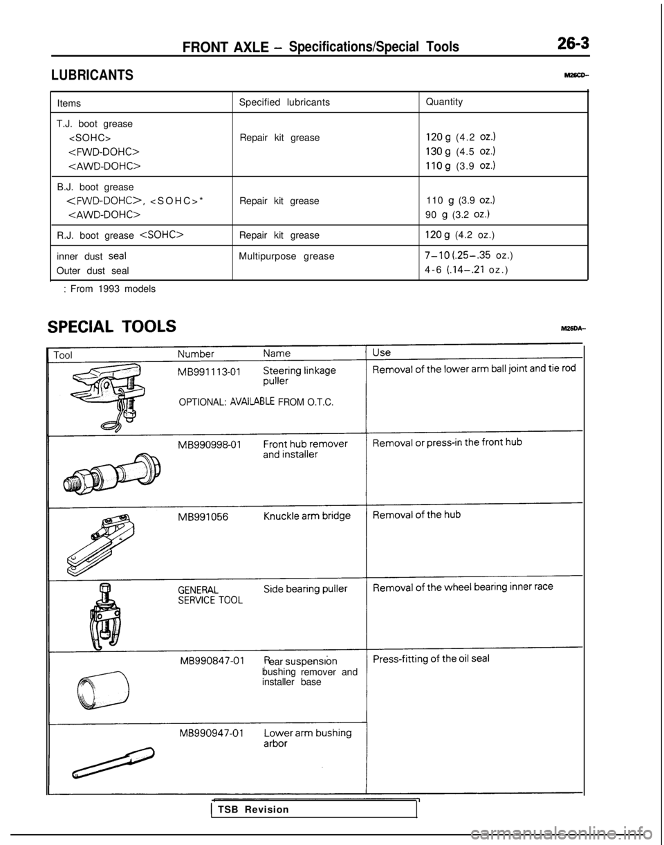
LUBRICANTS
FRONT AXLE -Specifications/Special Tools26-3
M26cD-
Items
T.J. boot grease
B.J. boot grease
*
R.J. boot grease
inner dust
seal
Outer dust seal
: From 1993 models Specified lubricants
Repair kit grease
Repair kit grease
Repair kit grease
Multipurpose grease Quantity
120 g (4.2 oz.)
130 g (4.5 oz.)
110 g (3.9 oz.)
110 g (3.9 oz.)
90 g (3.2 oz.)
120 g (4.2 oz.)
7-10 (.25-.35 oz.)
4-6
(.14-.21 oz.
)
SPECIAL TOOLSM26DA-
OPTIONAL: AVAilABLE FROM O.T.C.
ear
suspensron
bushing remover and
installer base
1 TSB Revision
Page 835 of 1273
FRONT AXLE - Troubleshooting/Service Adjustment Procedures26-5
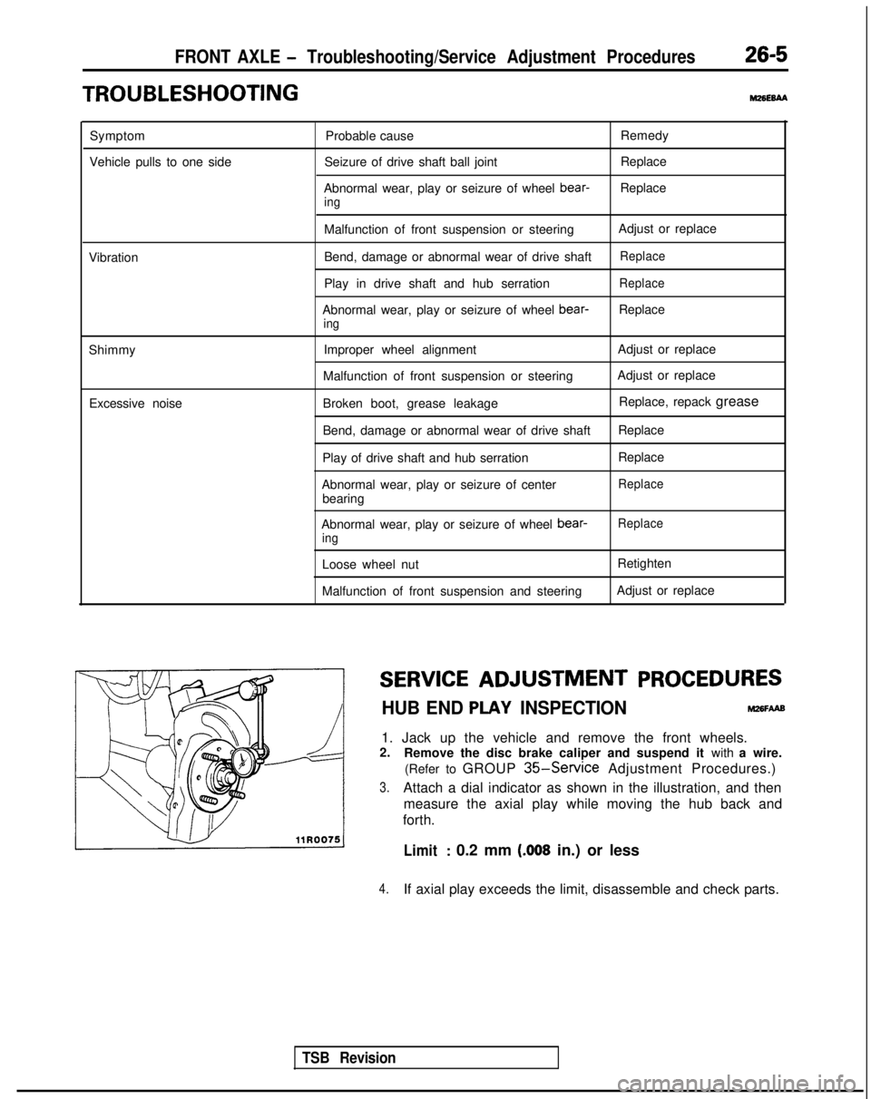
TROUBLESHOOTINGm6E6AA
Symptom
Vehicle pulls to one side Probable cause
Seizure of drive shaft ball joint
Abnormal wear, play or seizure of wheel bear-
ing
Remedy
Replace
Replace
Vibration
Shimmy Excessive noise Malfunction of front suspension or steering
Bend, damage or abnormal wear of drive shaft
Play in drive shaft and hub serration
Abnormal wear, play or seizure of wheel bear-
ing
Improper wheel alignment
Malfunction of front suspension or steering
Broken boot, grease leakage
Bend, damage or abnormal wear of drive shaft
Play of drive shaft and hub serration
Abnormal wear, play or seizure of center bearing Adjust or replace
Replace
Replace
Replace
Adjust or replace
Adjust or replace
Replace, repack grease
Replace
Replace
Replace
Abnormal wear, play or seizure of wheel bear-ing
Loose wheel nut
Malfunction of front suspension and steering
Replace
Retighten
Adjust or replace
SERVICE ADJUSTMENT
PROCEDURES
HUB END PLAY INSPECTIONM26FAAB
1. Jack up the vehicle and remove the front wheels.
2. Remove the disc brake caliper and suspend it with a wire.
(Refer to GROUP
35-Service Adjustment Procedures.)
3.Attach a dial indicator as shown in the illustration, and then measure the axial play while moving the hub back and
forth.
Limit: 0.2 mm (.008 in.) or less
4.If axial play exceeds the limit, disassemble and check parts.
TSB Revision
Page 842 of 1273
26-12FRONT AXLE - Hub and Knuckle/Drive Shaft
(2) Measure to determine whether the end play of the hub
is within the specified limit or not.
Limit: 0.2 mm
(.008 in.) or less
(3)If the starting torque and hub end play are not within the
limit range while the nut is tightened to 200-260 Nm
(144-
188 ft.lbs.), the bearing, hub and/or knuckle have
probably not been installed correctly. Repeat the
disassembly and assembly procedure.
r MB990998-01
2. INSTALLATION OF OIL SEAL (DRIVE SHAFT SIDE)
Drive the oil seal (drive shaft side) into the knuckle until it
contacts the snap ring.
Apply multipurpose grease to the lip of the oil seal.
MB990890-01
L
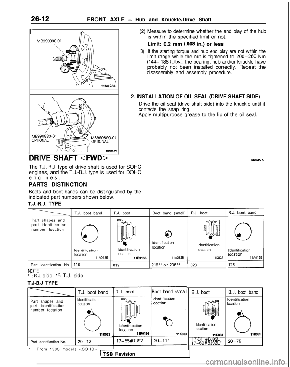
DRIVE SHAFT
The T.J.-R.J. type of drive shaft is used for SOHC
engines, and the
T.J.-B.J. type is used for DOHC
engines
.
PARTS DISTINCTION
Boots and boot bands can be distinguished by the
indicated part numbers shown below.
T.J.-R.J. TYPE
R.J. boot
T.J. boot band Boot band (small)
T.J. boot
a
,;: I
III 1it jii’
w
Part shapes and
part identification
number location
0
identification
location Identification
location Identification Identification
Identification
location location llA0125
llRO1!56
110019
llK033218” or
206*2 llA0125tI 020
Part identification No.
NOTE *‘:
R.J. side, *2: T.J. side
T.J-B.J TYPE
B.J. boot band
Identification
location
B.J. boot
Part shapes and
part identification number location
T.J. boot band
Identification
location
llK033
Part identification No. 20-12
Identification
location
llKO3317-31 #BJ92L17-69#BJ92L*20-75
i:: From 1993 models
Revision
Page 844 of 1273
 Use the general service tool to push out the dr")
26-14
FRONT AXLE - Drive Shaft
Pfb
1
+$$$A
y 7
@j
Qp I
\“dt 5
\
.i 1J Jd
llRO(O1 llE526
i+gJ#
\
‘II 1m\IIIJ I+
1
llE5309. REMOVAL OF DRIVE SHAFT
(1) Use the general service tool to push out the drive shaft
from the front hub.
(2) Insert a pry bar between the transaxle case and thedrive shaft, and then pry the drive shaft from the
transaxle.
Caution
1. Do not pull on the drive shaft; doing so will
damage the T.J.; be sure to use the pry bar.
2.Do not insert the pry bar so deep as to damage
the oil seal.
Caution
Do not apply the vehicle weight to the wheel bearing
while the drive shaft is disconnected. If the vehicle
weight must unavoidably be applied (because of
vehicle movement or some other reason), use the
special tool to hold the wheel bearing, as shown in the
figure.
4.INSTALlATlON OF WASHER/3. DRIVE SHAFT NUT/P.
COTTER PIN
(1) Be sure to install the washer and wheel bearing nut in
the specified direction.
(2) After installing the wheel, lower the vehicle to the
ground and finally tighten the wheel bearing nut.
(3) If the position of the cotter pin holes does not match, tighten the nut up to 260 Nm (188
ft.lbs.) in maximum.
(4) Install the cotter pin in the first matching holes and
bend it securely.
TSB Revision
INSPECTIONM28OChC
lCheck the drive shaft boot for damage or deterioration.
l Check the ball joints for wear or operating condition.
l Check the spline part for wear or damage.
SERVICE POINTS OF INSTALLATION
w26QDAJ
6. INSTALLATION OF LOWER ARM BALL JOINT
Lower the vehicle to the ground and tighten the knuckle to
the lower arm ball joint connecting nut.