boot MITSUBISHI GALANT 1989 Service Owner's Manual
[x] Cancel search | Manufacturer: MITSUBISHI, Model Year: 1989, Model line: GALANT, Model: MITSUBISHI GALANT 1989Pages: 1273, PDF Size: 37.62 MB
Page 845 of 1273
FRONT AXLE -Drive Shaft (T.J.-R.J.
Type)26-15
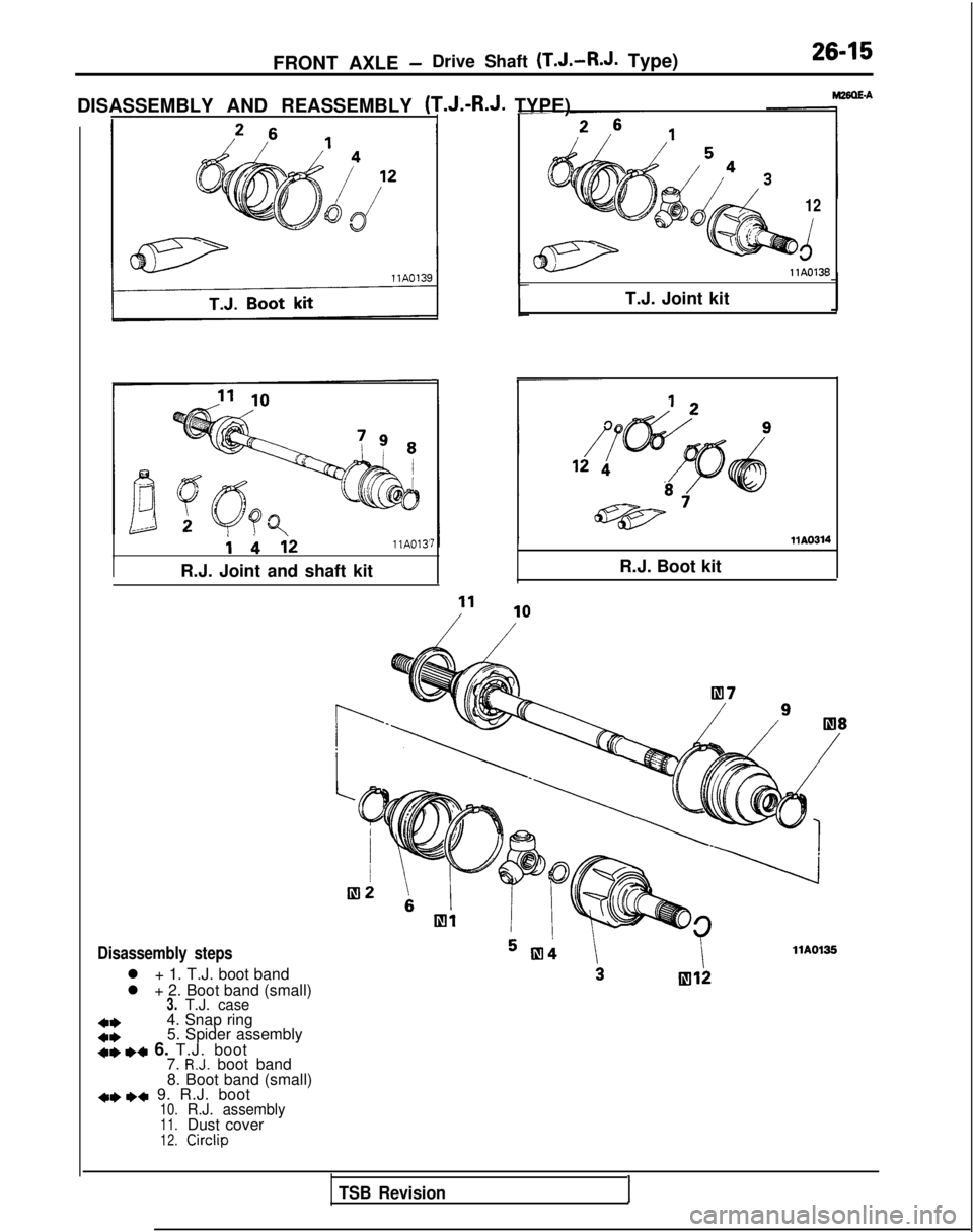
DISASSEMBLY AND REASSEMBLY (T.J.-R.J. TYPE) i
bi2llA013'
IR.J. Joint and shaft kit
Disassembly steps
l + 1. T.J. boot band
l + 2. Boot band (small)
3.T.J. case
+*4. Snap ring
4*5. Spider assembly+e ,+ 6. T.J. boot
7. R.J. boot band
8. Boot band (small)
+e I)+ 9. R.J. boot10.R.J. assembly11.Dust cover12.Circlip
T.J. Joint kit
12
d llA0138
R.J. Boot kit
llA0135
TSB Revision1
Page 846 of 1273
26-16
FRONT AXLE -Drive Shaft (T.J.-R.J.
Type)
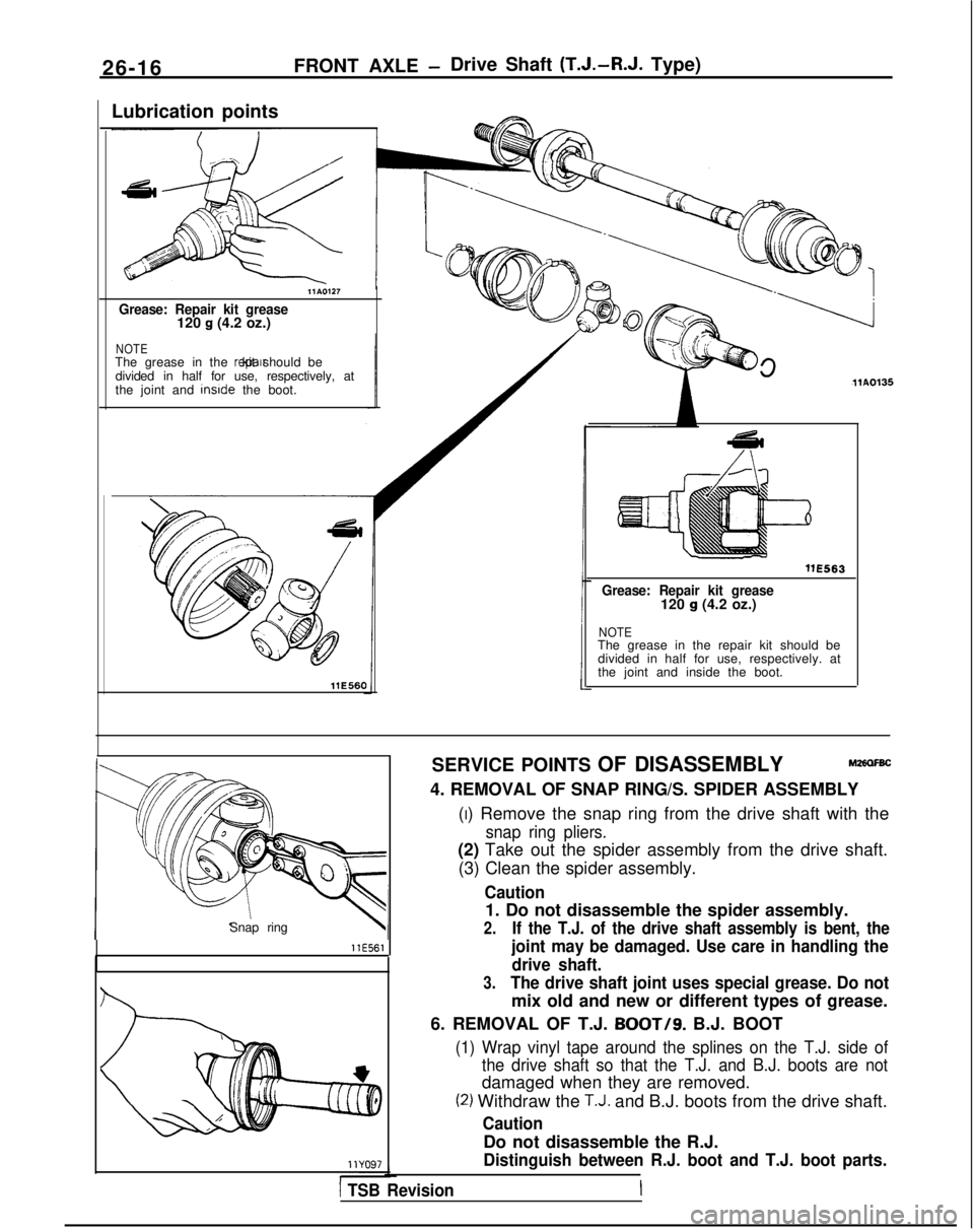
Lubrication points
llA0127
Grease: Repair kit grease120 g (4.2 oz.)
NOTEThe grease in the repalr kit should be
divided in half for use, respectively, at
the joint and inslde
the boot.
llE560 llA0135
WE563
Grease: Repair kit grease120 g (4.2 oz.)
NOTEThe grease in the repair kit should be
divided in half for use, respectively. at
the joint and inside the boot.
Snap ring
llE561
SERVICE POINTS OF DISASSEMBLYM2alFBC
4. REMOVAL OF SNAP RING/S. SPIDER ASSEMBLY (I) Remove the snap ring from the drive shaft with the
snap ring pliers.
(2) Take out the spider assembly from the drive shaft.(3) Clean the spider assembly.
Caution
1. Do not disassemble the spider assembly.
2.If the T.J. of the drive shaft assembly is bent, the
joint may be damaged. Use care in handling the drive shaft.
3.The drive shaft joint uses special grease. Do not
mix old and new or different types of grease.
6. REMOVAL OF T.J.
BOOT/g. B.J. BOOT
(1) Wrap vinyl tape around the splines on the T.J. side of the drive shaft so that the T.J. and B.J. boots are not
damaged when they are removed.
(2) Withdraw the T.J. and B.J. boots from the drive shaft.
Caution
Do not disassemble the R.J.
Distinguish between R.J. boot and T.J. boot parts.
1 TSB Revision
Page 847 of 1273
FRONT AXLE -Drive Shaft (T.J.-R.J.
Type)26-17
INSPECTIONM26OGBC
l Check the drive shaft for damage, bending or corrosion.
l Check the drive shaft
splines for wear or damage.
lCheck for entry of water and/or foreign material into R.J.
l Check the spider assembly for roller rotation, wear or
corrosion.
lCheck the groove inside T.J. case for wear or corrosion.
l Check the boots for deterioration, damage or cracking.
SERVICE POINTS OF REASSEMBLY
MZbOHBE
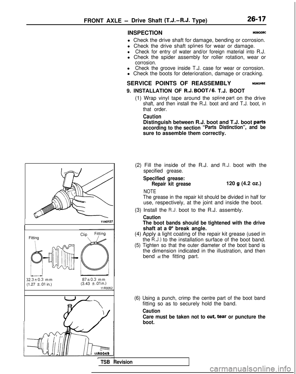
9. INSTALLATION OF R.J. BOOT/6.
T.J. BOOT
(1) Wrap vinyl tape around the
spline part on the drive
shaft, and then install the R.J. boot and and T.J. boot, in
that order.
Caution
Distinguish between R.J. boot and T.J. boot parts
according to the section“Parts Distinction”, and be
sure to assemble them correctly.
llAQl27
Fitting
32320.3 m
m
8720.3 m
m
(1.27
2 .Ol in.) (3.43 k .Ol u7.111 R005i
i-lj4AI Al II III L-1 llR0049ITSB Revision
(2) Fill the inside of the R.J. and R.J. boot with the
specified grease.
Specified grease:
Repair kit grease120 g (4.2 oz.)
NOTE
The grease in the repair kit should be divided in half for
use, respectively, at the joint and inside the boot.
(3) Install the
R.J. boot to the R.J. assembly.
Caution
The boot bands should be tightened with the drive
shaft at a 0” break angle.
(4) Apply a light coating of the repair kit grease (used in
the
R.J.) to the installation surface of the boot band.
(5) Tighten so that the outer diameter of the boot band is
the dimension indicated in the illustration, and thenbend at the fitting part.
(6) Using a punch, crimp the centre part of the boot band
fitting so as to securely hold the band.
Caution
Care must be taken not to cut,.tear or puncture the
boot.
Page 848 of 1273
26-18FRONT AXLE - Drive Shaft (T.J.-R.J.
Type)
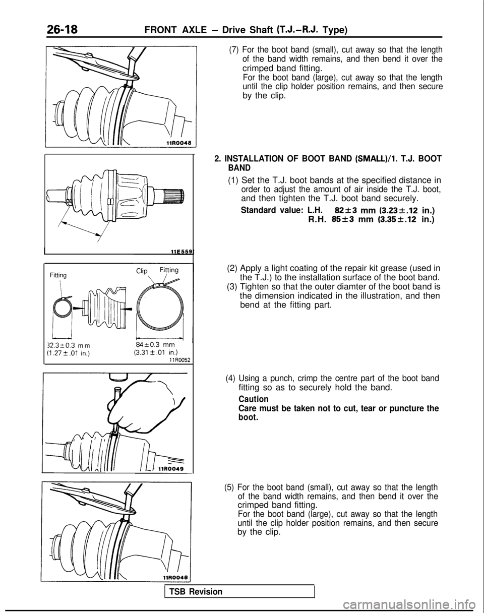
(7) For the boot band (small), cut away so that the length
of the band width remains, and then bend it over the
crimped band fitting.
For the boot band (large), cut away so that the length
until the clip holder position remains, and then secure
by the clip.
Fitting 32.3kO.3
mm
(I .27 t .Ol in.) llR0052
2. INSTALLATION OF BOOT BAND (SMALL)/l.
T.J. BOOT
BAND
(1) Set the T.J. boot bands at the specified distance in
order to adjust the amount of air inside the T.J. boot,
and then tighten the T.J. boot band securely.
Standard value: L.H.82+3 mm (3.23k.12
in.)
R.H.
85+3 mm (3.35f.12 in.)
(2) Apply a light coating of the repair kit grease (used in the T.J.) to the installation surface of the boot band.
(3) Tighten so that the outer diamter of the boot band is the dimension indicated in the illustration, and thenbend at the fitting part.
(4) Using a punch, crimp the centre part of the boot band
fitting so as to securely hold the band.
Caution
Care must be taken not to cut, tear or puncture the
boot.
(5) For the boot band (small), cut away so that the length of the band width remains, and then bend it over the
crimped band fitting.
For the boot band (large), cut away so that the length
until the clip holder position remains, and then secure
by the clip.
TSB Revision
Page 849 of 1273
FRONT AXLE -Drive Shaft ‘(T.J.-B.J. Type)26-19
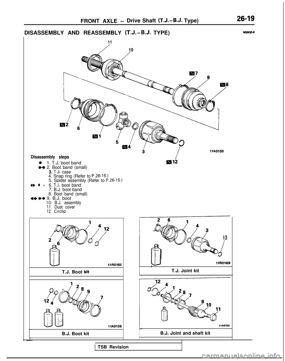
DISASSEMBLY AND REASSEMBLY (T.J.-B.J. TYPE)
11
/10
Disassembly steps
l 1. T.J. boot bandM 2. Boot band (small)3. T.J. case
4. Snap ring (Refer to P.26-16.)5. Spider assembly (Refer to P.26-16.)
4I) l +6. TIJ. boot band
7. B.J. boot band
8. Boot band (small)+I)*+ 9. B.J. boot10.B.J. assembly11.Dust cover12.Circlip llR016E
T.J. Boot
kit llA0126
B.J. Boot kit llA0135
3”12
d.
LIllR0169
T.J. Joint kit
llA0132
B.J. Joint and shaft kit
1 TSB Revision
Page 850 of 1273
26-20FRONT AXLE - Drive Shaft (T.J.-B.J. Type)
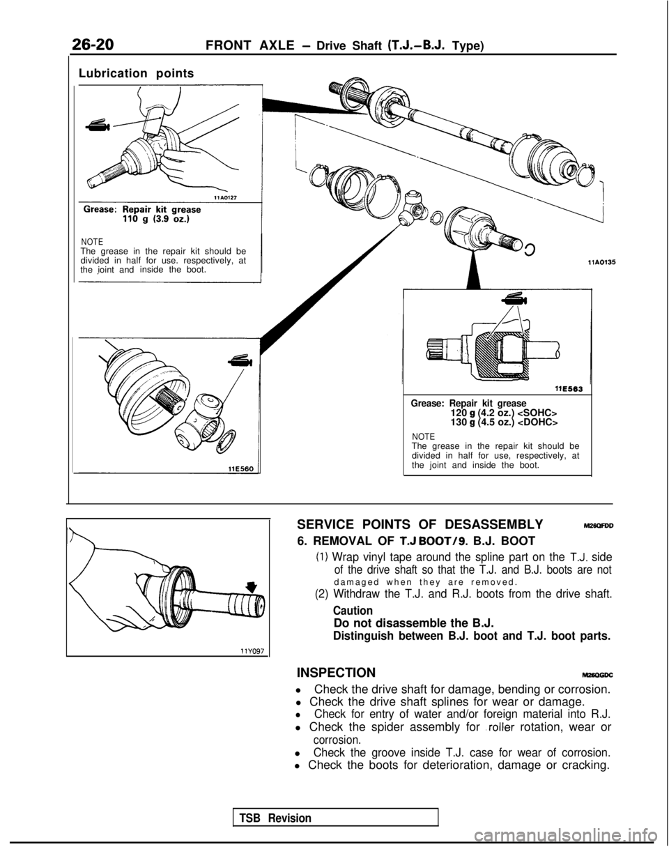
Lubrication points
NOTEThe grease in the repair kit should be divided in half for use. respectively, at
the ioint and inside the
boot. 11E563
Grease: Repair kit grease120 g (4.2 oz.)
130 g (4.5 oz.)
NOTEThe grease in the repair kit should be
divided in half for use, respectively, at
the joint and inside the boot.
SERVICE POINTS OF DESASSEMBLY
M2mFDD
6. REMOVAL OF T.J BOOT/g. B.J. BOOT (1)
Wrap vinyl tape around the spline part on the T.J. side
of the drive shaft so that the T.J. and B.J. boots are not
damaged when they are removed
.
(2) Withdraw the T.J. and R.J. boots from the drive shaft.
Caution
Do not disassemble the B.J.
Distinguish between B.J. boot and T.J. boot parts.
INSPECTIONM26D6Dc
l
Check the drive shaft for damage, bending or corrosion.
l Check the drive shaft splines for wear or damage.
lCheck for entry of water and/or foreign material into R.J.
l Check the spider assembly for ,roller rotation, wear or
corrosion.
lCheck the groove inside T.J. case for wear of corrosion.
l Check the boots for deterioration, damage or cracking.
TSB Revision
Page 851 of 1273
FRONT AXLE -Drive Shaft (T.J.-B.J. Type)26-21
SERVICE POINTS OF REASSEMBLYM26OtlDE
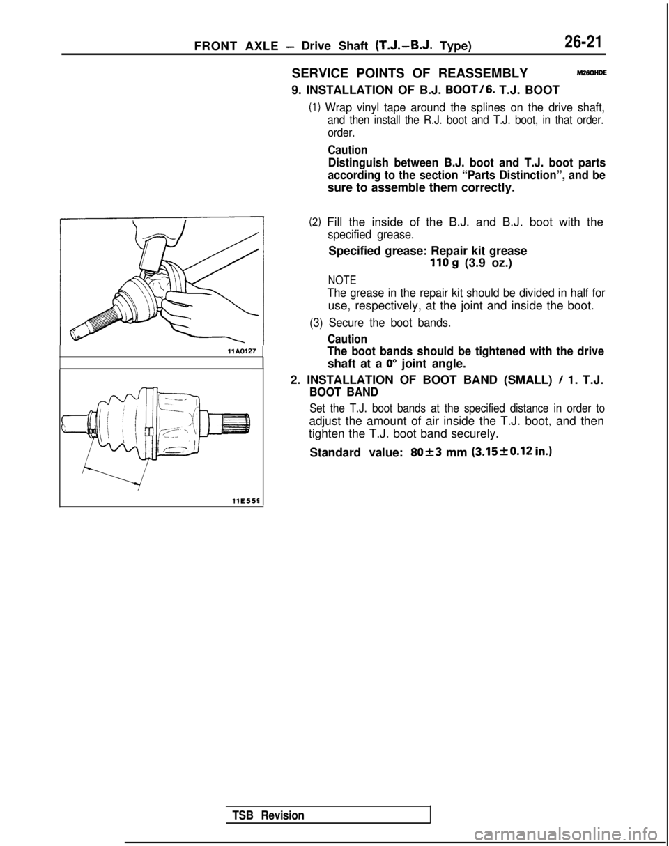
9. INSTALLATION OF B.J.
BOOT/6.
T.J. BOOT
(1) Wrap vinyl tape around the splines on the drive shaft,
and then install the R.J. boot and T.J. boot, in that order.
order.
Caution
Distinguish between B.J. boot and T.J. boot parts
according to the section “Parts Distinction”, and be
sure to assemble them correctly.
(2) Fill the inside of the B.J. and B.J. boot with the
specified grease.
Specified grease: Repair kit grease
110 g (3.9 oz.)
NOTE
llAOl27
The grease in the repair kit should be divided in half for
use, respectively, at the joint and inside the boot.
(3) Secure the boot bands.
Caution
The boot bands should be tightened with the drive
shaft at a 0” joint angle.
2. INSTALLATION OF BOOT BAND (SMALL)
/ 1. T.J.
BOOT BAND
Set the T.J. boot bands at the specified distance in order to
adjust the amount of air inside the T.J. boot, and then
tighten the T.J. boot band securely.
Standard value:
8023 mm (3.15f0.12 in.)
llE55E
TSB Revision
Page 852 of 1273
FRONT AXLE - Drive Shaft
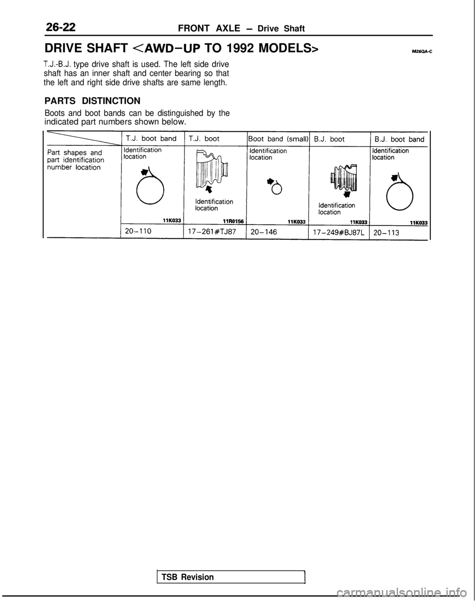
DRIVE SHAFT
T.J.-B.J. type drive shaft is used. The left side drive
shaft has an inner shaft and center bearing so that
the left and right side drive shafts are same length.
PARTS DISTINCTION
Boots and boot bands can be distinguished by the
indicated part numbers shown below.
TSB Revision
Page 854 of 1273
26-24FRONT AXLE - Drive Shaft
C
I1
c
1:
9
M8
Pry barTrarkaxlellE526
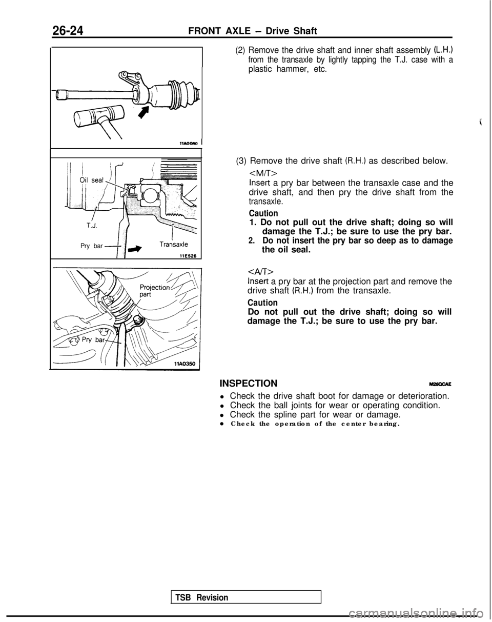
(2) Remove the drive shaft and inner shaft assembly (L.H.)
from the transaxle by lightly tapping the T.J. case with a
plastic hammer, etc.
(3) Remove the drive shaft (R.H.) as described below.
drive shaft, and then pry the drive shaft from the
transaxle.
Caution
1. Do not pull out the drive shaft; doing so will damage the T.J.; be sure to use the pry bar.
2.Do not insert the pry bar so deep as to damage
the oil seal.
Inset-t a pry bar at the projection part and remove the
drive shaft
(R.H.) from the transaxle.
Caution
Do not pull out the drive shaft; doing so will
damage the T.J.; be sure to use the pry bar.
INSPECTION l Check the drive shaft boot for damage or deterioration.
l Check the ball joints for wear or operating condition.
l Check the spline part for wear or damage.
l Check the operation of the center bearing.
TSB Revision
Page 855 of 1273
l +3. T.J. case and inner shaf")
FRONT AXLE - Drive Shaft26-25
DISASSEMBLY ANDREASSEMBLY
\
T.J. boot repair kit
T.J. kit
B.J. boot repair kit
Disassembly steps
l +1. T.J. boot bandl +2. Boot band (small)l +3. T.J. case and inner shaft assembly4. T.J. case
5. Seal plate
+ee* 6. Inner shaft7. Bracket assemblyI&+ 8. Outer dust sealW4 9. Inner dust seal +e l
+ 10. Center bearing11. Center bearino bracket12. Circlip -13. Snap ring (Refer to P.26-17.)14. Spider assembly (Refer to P.26-17.) llA0315
B.J. kii
,,A0113
Bearing dust seal kii llA0317
Bracket assembly kii
15. T.J. boot (Refer to P.26-17, 18.116. B.J. boot band
17. Boot band (small)
18. B.J. boot (Refer to P.26-17. 18.)19. B.J. assembly
20. Dust cover
TSB Revision