air conditioning MITSUBISHI GALANT 1989 Service Manual PDF
[x] Cancel search | Manufacturer: MITSUBISHI, Model Year: 1989, Model line: GALANT, Model: MITSUBISHI GALANT 1989Pages: 1273, PDF Size: 37.62 MB
Page 428 of 1273
13-286FUEL SYSTEM
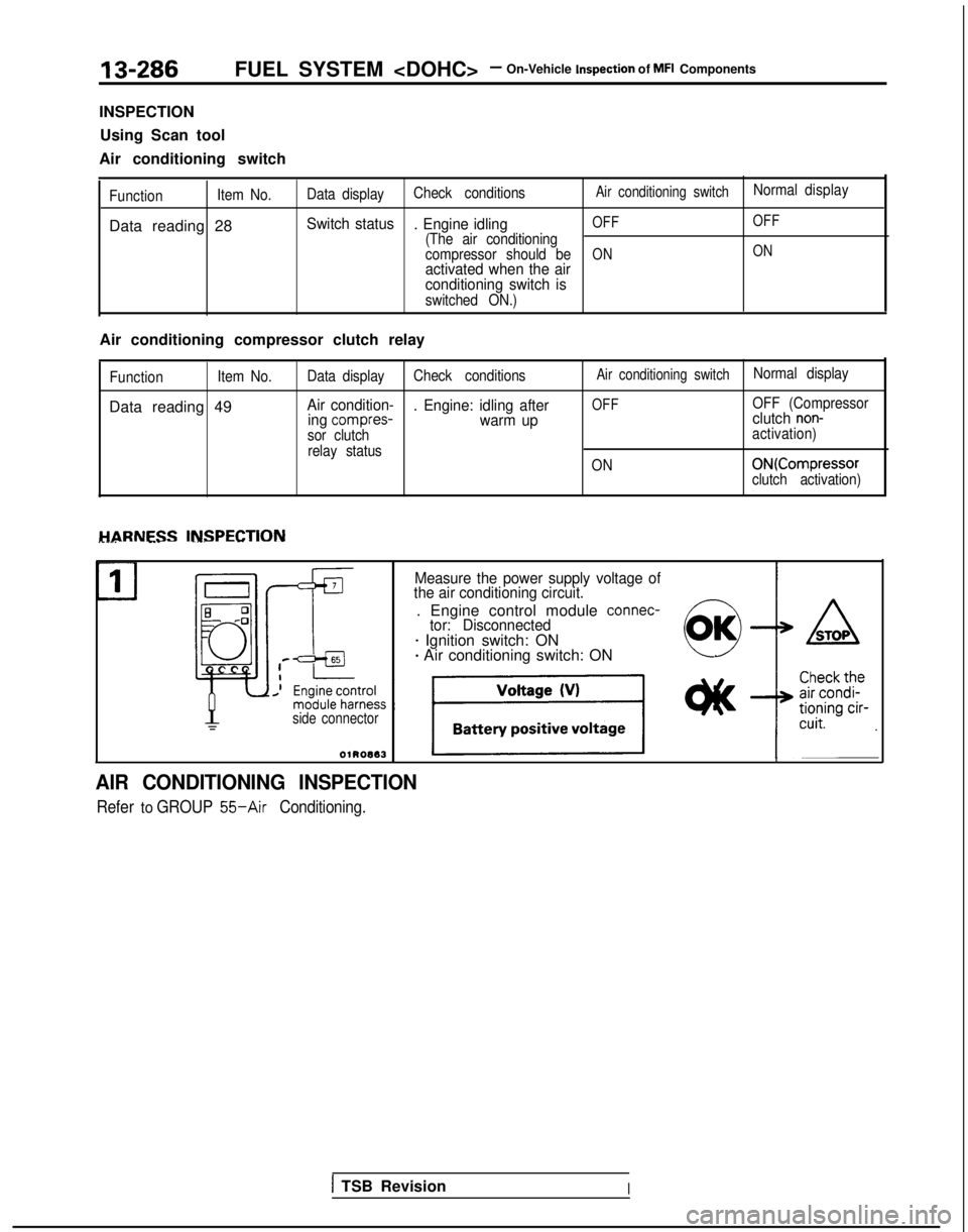
INSPECTION Using Scan tool
Air conditioning switch
Function Item No.
Data reading 28
Data displayCheck conditionsAir conditioning switchNormal
display
Switch status
. Engine idlingOFF OFF
(The air conditioning
compressor should beONONactivated when the air
conditioning switch is
switched ON.)
Air conditioning compressor clutch relay
Function
Item No.
Data reading 49
Data display
Check conditionsAir conditioning switchNormal display
Air condition-
. Engine: idling afterOFFOFF (Compressor
ing compres-warm up clutch non-
sor clutch
activation)
relay status ON
ONKompressorclutch activation)
HARNESS INSPECTION________ --- -__-. -- ~~-
Measure the power supply voltage of
the air conditioning circuit.
. Engine control module connec-tor: Disconnected- Ignition switch: ON+ Air conditioning switch: ON
side connector
AIR CONDITIONING INSPECTION
Refer to GROUP 55-Air Conditioning.
1 TSB RevisionI
Page 441 of 1273
FUEL SYSTEM
MFI Components13-299
OPERATION
l The amount of air taken in during idling is
regulated by the opening and closing of the
servo valve located in the air passage that
bypasses the throttle valve.
l The servo valve is opened or closed by the
activation of the stepper motor (incorporated
within the idle air control motor) in the forward
or reverse direction.
TROUBLESHOOTING HINTS
Hint 1: If the number of stepper motor steps increases to
IOO- 120 steps or decreases
to 0 step, the cause may be presumed to be a malfunction of the stepper motor or
damaged or disconnected wiring of the
harness.
Hint 2: If the number of stepper motor steps
deviates from the standard value even
though the results of the checking of the
harness of the idle air control motor and of
the comoonent
itself indicate no abnormal
condition, the cause may be presumed to be one of the following.
INSPECTION
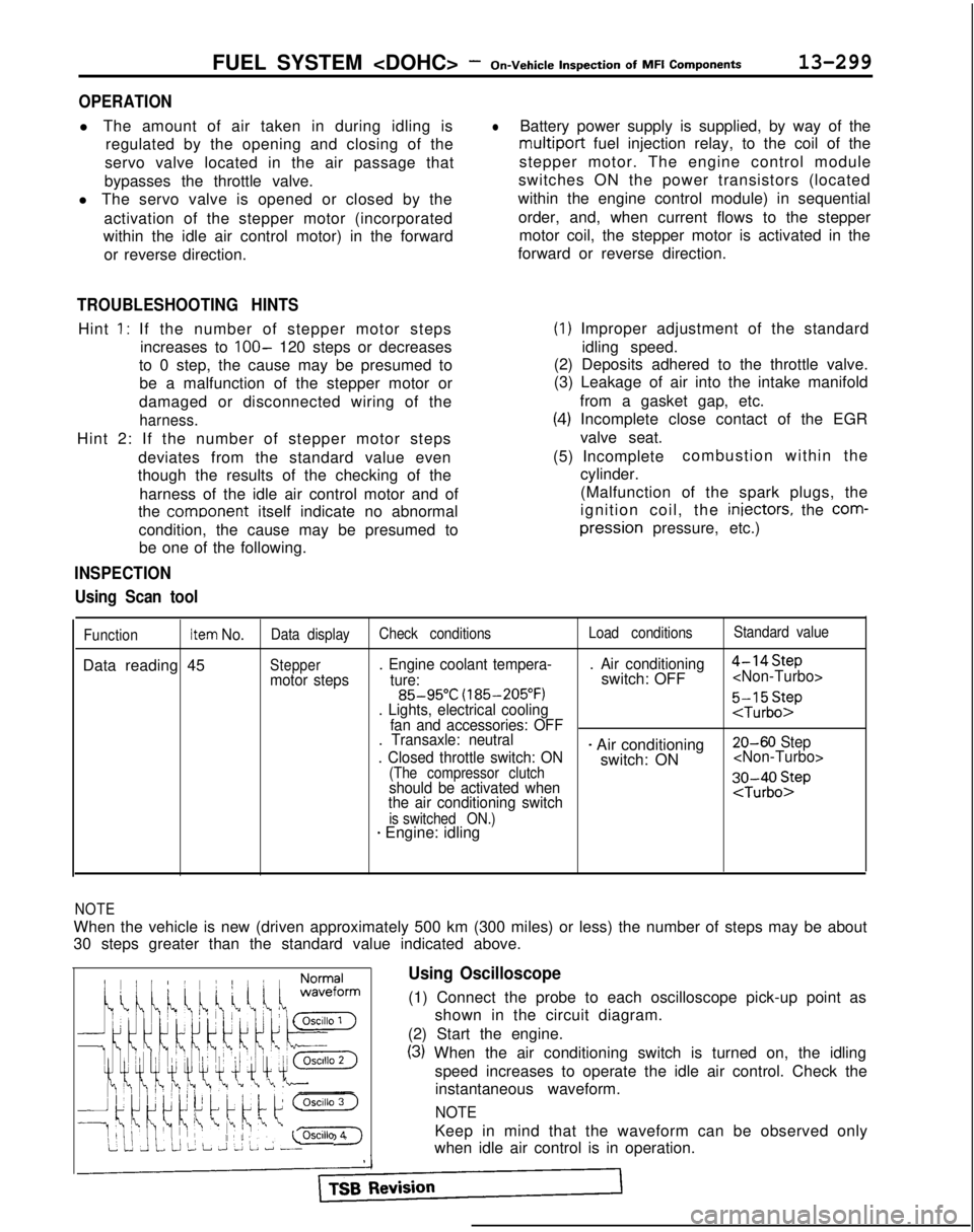
Using Scan tool
lBattery power supply is supplied, by way of the
multiport fuel injection relay, to the coil of the
stepper motor. The engine control module
switches ON the power transistors (located
within the engine control module) in sequential
order, and, when current flows to the stepper motor coil, the stepper motor is activated in the
forward or reverse direction.
(1) Improper adjustment of the standard
idling speed.
(2) Deposits adhered to the throttle valve.
(3) Leakage of air into the intake manifold
from a gasket gap, etc.
(4) Incomplete close contact of the EGRvalve seat.
(5) Incomplete combustion within the
cylinder.
(Malfunction of the spark plugs, the
ignition coil, the iniectors,
the
com- pression
pressure, etc.)
FunctionItem No.Data display Check conditions Load conditionsStandard value
Data reading 45Steppermotor steps. Engine coolant tempera-
. Air conditioning
4-14Step
ture:switch: OFF
(185-205°F)
. Lights, electrical cooling
:$b::pfan and accessories: OFF
. Transaxle: neutral
. Closed throttle switch: ON
- Air conditioning 20-60 Step
switch: ON
(The compressor clutchshould be activated when
the air conditioning switch;J-;;o~P
is switched ON.)* Engine: idling
1;:!,1;:!,
/!-I\/!-I\
f$&$:”f$&$:”
! ,‘,! ,‘,
4);4);
;jj\(Q(j!jGZ-);jj\(Q(j!jGZ-)
lili
q#Q~Hq#Q~HF]F]
ii 2 L J 2 L ~ -0SClllO 4ii 2 L J 2 L ~ -0SClllO 4
NOTE
When the vehicle is new (driven approximately 500 km (300 miles) or l\
ess) the number of steps may be about
30 steps greater than the standard value indicated above.
Using Oscilloscope
(1) Connect the probe to each oscilloscope pick-up point as
shown in the circuit diagram.
(2) Start the engine.
(3) When the air conditioning switch is turned on, the idling speed increases to operate the idle air control. Check theinstantaneous waveform.
NOTE
Keep in mind that the waveform can be observed only
when idle air control is in operation.
Page 458 of 1273
13-316FUEL SYSTEM
Inspection
of
MFI
Components
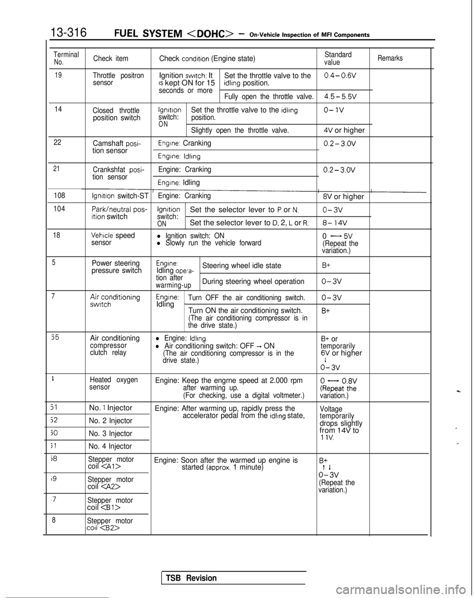
TerminalNo.Check itemCheck condition (Engine state)Standardvalue
Remarks
19Throttle positronIgnition switch: ItSet the throttle valve to the0.4- 0.wsensorIS kept ON for 15seconds or moreidlrng position.
Fully open the throttle valve.4.5- 5.5v
14
Closed throttlelgnrtrono-1vposition switchswitch:Set the throttle valve to the idling
position.
ONSlightly open the throttle valve.4V or higher
22Camshaft posi-tion sensorEngine: Cranking0.2- 3.ov
Engine: ldlrng
21
Crankshfat posi-tion sensor Engine: Cranking0.2- 3.ov
Engine: Idling
108lgnrtion switch-STEngine: Cranking8V or higher
104
Park/neutral
pos-ition switchIgnitionSet the selector lever to P or N.o-3vswitch:ONSet the selector lever to D, 2, L or R.8- 14V
18Vehicle speedl Ignition switch: ON
sensorl Slowly run the vehicle forward0 - 5v(Repeat the
variation.)
5Power steering
pressure switchEngine:Idling opera-Steering wheel idle stateB+
tion afterwarming-upDuring steering wheel operationo-3v
7A&;;;ditioningEngine:Idling _Turn OFF the air conditioning switch.o-3v
Turn ON the air conditioning switch.B+
(The air conditioning compressor is in
the drive state.)
35Air conditioningl Engine: IdlingB+ orcompressor
clutch relayl Air conditioning switch: OFF -, ON(The air conditioning compressor is in the
temporarily
drive state.)6V or higher o’-
3v
1Heated oxygen
sensorEngine: Keep the engrne speed at 2.000 rpmafter warming up.
(For checking, use a digital voltmeter.)ke;atoZivariation.)
51No. 1 InjectorEngine: After warming up, rapidly press the
52No. 2 Injector accelerator pedal from the idlrng state,Voltage
temporarily
drops slightly
30No. 3 Injectorfrom 14V to1 IV.
51No. 4 Injector
j8
Stepper motorcoil
i9
Stepper motor0%
coil
variation.)
‘7Stepper motorcoil
8Stepper motorco11
TSB Revision
Page 540 of 1273
13-398
AUTO-CRUISE CONTROL SYSTEM - Setice Adjustment procedures
03*02.5*
1
AUTO-CRUISE CONTROL CANCELLATION CHECK
(1) Set the auto-cruise control.
(2) Check to be sure that there is a return to ordinary driving,
and that the illumination of the auto-cruise indicator stops,
when either of the operations below is performed. @ The brake pedal is depressed.
@ The clutch pedal is depressed.
@ TJhEzift lever is moved to the “N” or “P” range.
@I The auto-cruise control main switch is switched OFF.
@ The ignition switch is turned to OFF.
CHECK OF RETURN TO THE SET SPEED BEFORE
CANCELLATION (1) Set the auto-cruise control.
(2) Check to be sure that the auto-cruise control is
cancelled
when either of the operations below is performed.
@ The brake pedal is depressed.
@ The clutch pedal is depressed.
CAST>
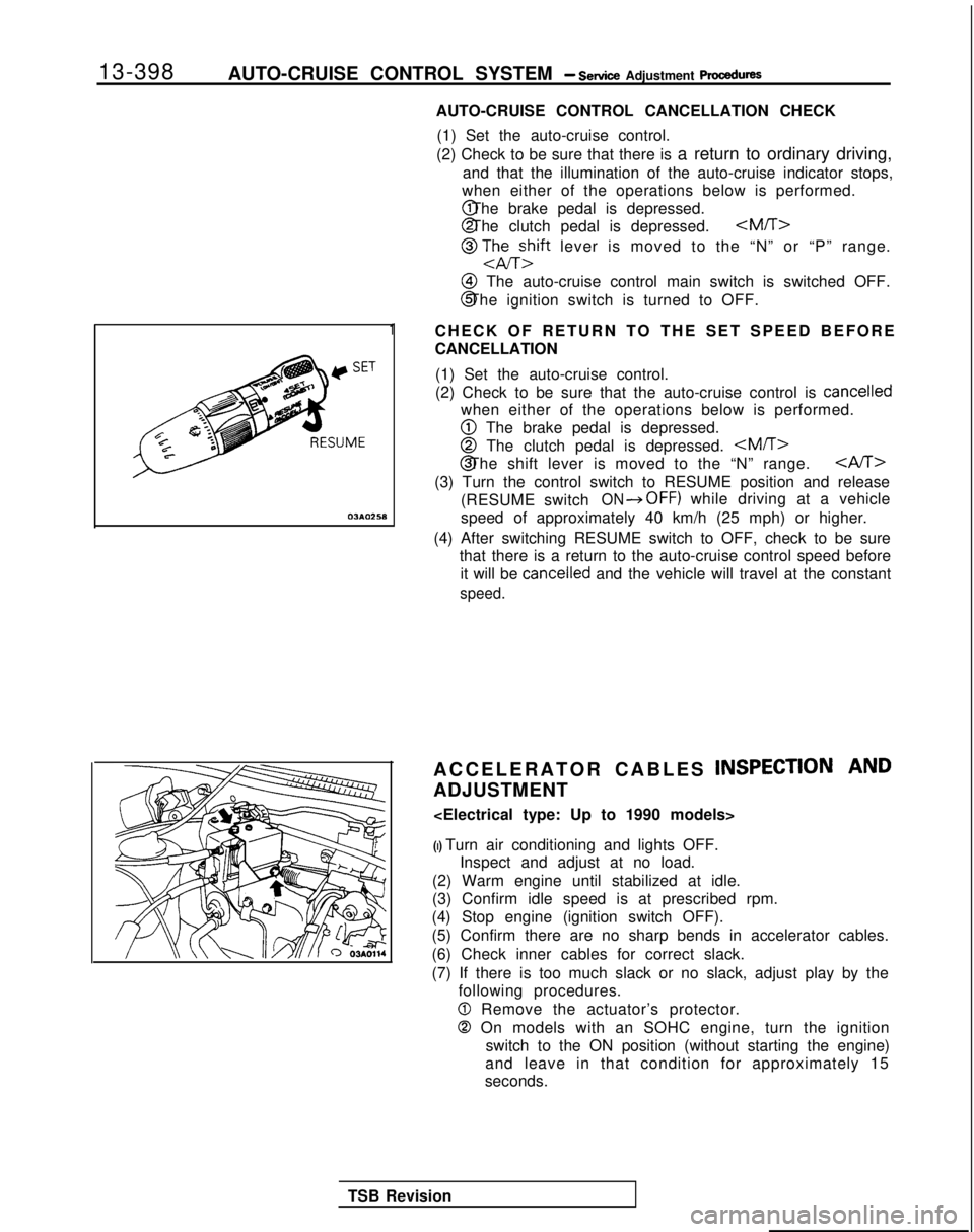
(3) Turn the control switch to RESUME position and release
(RESUME switch
ON*OFF) while driving at a vehicle
speed of approximately 40 km/h (25 mph) or higher.
(4) After switching RESUME switch to OFF, check to be sure that there is a return to the auto-cruise control speed before
it will be
cancelled and the vehicle will travel at the constant
speed.
ACCELERATOR CABLES INSPECTION AND
ADJUSTMENT
(I) Turn air conditioning and lights OFF. Inspect and adjust at no load.
(2) Warm engine until stabilized at idle.
(3) Confirm idle speed is at prescribed rpm.
(4) Stop engine (ignition switch OFF).
(5) Confirm there are no sharp bends in accelerator cables.
(6) Check inner cables for correct slack.
(7) If there is too much slack or no slack, adjust play by the following procedures.
0 Remove the actuator’s protector.
0 On models with an SOHC engine, turn the ignition
switch to the ON position (without starting the engine)
and leave in that condition for approximately 15
seconds.
TSB Revision
Page 554 of 1273
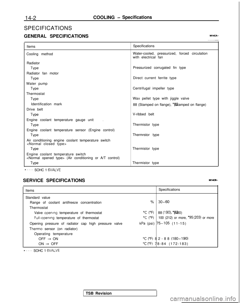
14-2
COOLING- Specifications
SPECIFICATIONS
GENERAL SPECIFICATIONS
MlICA-
Items
Cooling method Specifications
Water-cooled, pressurized, forced circulation
with electrical fan
Radiator Type
Radiator fan motor Type
Water pump Type
Thermostat Type
Identification mark
Drive belt Type
.Engine coolant temperature gauge unit
Type
Engine coolant temperature sensor (Engine control) Type
Air conditioning engine coolant temperature switch
Engine coolant temperature switch
* . . .SOHC 1 GVALVE
Pressurized corrugated fin type
Direct current ferrite type
Centrifugal impeller type
Wax pellet type with jiggle valve 88 (Stamped on flange), *82 (Stamped on flange)
V-ribbed belt
Thermistor type
Thermrstor type
Thermistor type
Thermistor type
SERVICE SPECIFICATIONS
MlOCB-
Items
Standard value Range of coolant antifreeze concentration
Thermostat Valve opening
temperature of thermostat Full-opening
temperature of thermostat
Opening pressure of radiator cap high pressure valve Therm0
sensor (on radiator)
Operating temperature OFF
+ ON
ON
+ OFF
* . . .SOHC 1 GVALVE
Specifications
% 30-60
“C (“F)88 (IgO), *82 (180)
T (OF)100 (212) or more, *95 (203) or more
kPa (psi) 75-105 (11-15
)
“C (“F) 82-88 (180-190)
“C (“F) 78-84 (172-183
)
TSB Revision
Page 555 of 1273
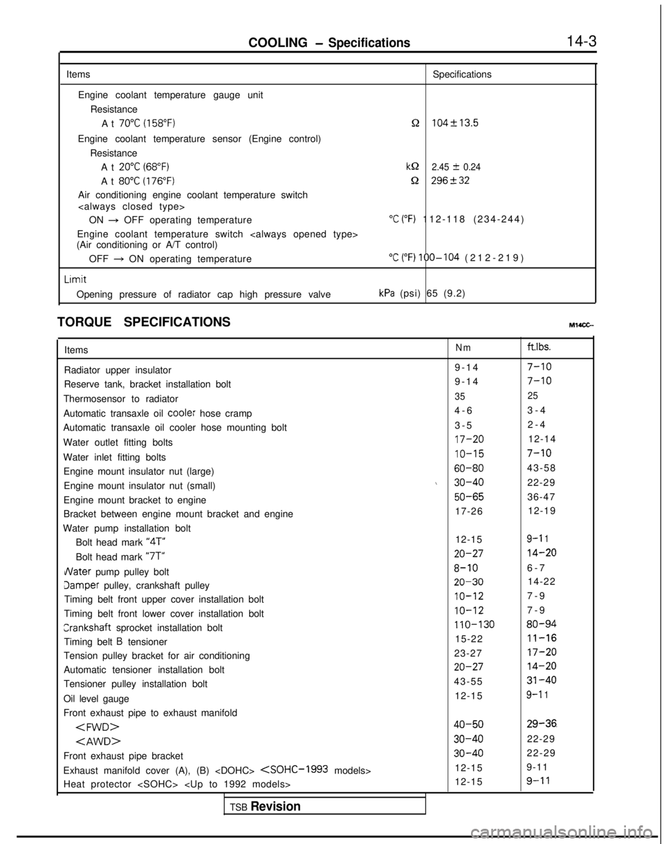
COOLING- Specifications14-3
Items Specifications
Engine coolant temperature gauge unit ResistanceAt
70°C (158°F)n 104f13.5
Engine coolant temperature sensor (Engine control) ResistanceAt
20°C (68°F)kQ 2.45 f 0.24
At 80°C (176°F)Q 296+32
Air conditioning engine coolant temperature switch
ON
+ OFF operating temperature“C (“F) 112-118 (234-244
)
Engine coolant temperature switch
(Air conditioning or A/T control)
OFF
+ ON operating temperature“C (“F) 100-104 (212-219
)
Limit
Opening pressure of radiator cap high pressure valvekPa (psi) 65 (9.2)
TORQUE SPECIFICATIONS
MWCG-
ItemsNm ft.lbs.
Radiator upper insulator 9-14
7-10
Reserve tank, bracket installation bolt9-1
4
7-10
Thermosensor to radiator35
25
Automatic transaxle oil coole: hose cramp 4-
6
3-4
Automatic transaxle oil cooler hose mounting bolt 3-5
2-4
Water outlet fitting bolts
17-2012-14
Water inlet fitting bolts
IO-157-10
Engine mount insulator nut (large)60-8043-58
Engine mount insulator nut (small)
\ 30-4022-29
Engine mount bracket to engine
50-6536-47
Bracket between engine mount bracket and engine 17-26
12-19
Water pump installation bolt Bolt head mark “4T”
12-15
9-l 1
Bolt head mark “7T”20-2714-20
dater pump pulley bolt8-106-
7
Jamper pulley, crankshaft pulley20-3014-22
Timing belt front upper cover installation bolt
IO-127-
9
Timing belt front lower cover installation bolt
IO-127-
9
Crankshaft
sprocket installation bolt
110-13080-94
Timing belt B tensioner 15-2211-16
Tension pulley bracket for air conditioning
23-2717-20
Automatic tensioner installation bolt20-2714-20
Tensioner pulley installation bolt43-5531-40
Oil level gauge 12-159-l 1
Front exhaust pipe to exhaust manifold
Front exhaust pipe bracket
30-4022-29
Exhaust manifold cover (A), (B)
9-11
Heat protector
TSB Revision
Page 556 of 1273

14-4COOLING-Specifications
Items
Exhaust manifold to cylinder head
< 1993 models>
Engine hanger to engine bracket
Oxygen sensor
Water inlet pipe installation bolt Transaxle side
Engine block side
< 1993 models>
Engine coolant temperature gauge unit
Engine coolant temperature sensor (Engine control)
Air conditioning engine coolant temperature switch
Engine coolant temperature switch
(Air conditioning or A/T control) Rocker cover installation bolt
Exhaust manifold to turbocharger
Eye bolt (oil pipe)
Air outlet fitting installation bolt
Water pipe
B
Front exhaust pipe to turbocharger
Eye bolt (water pipe)
Water pipe
B clamp
Oil return pipe
Water hose installation bolt
Nater hose to turbocharger
Ixhaust pipe support bracket
Exhaust pipe support bracket to front exhaust pipe Nm ft.lbs.
15-2011-14
25-3018-22
27-3320-23
25-3018-22
12-15 9-11
40-5029-36
43-55
31-40
IO-157-10
12-15 9-11
IO-127-
9
20-4014-29
30-4022-29
IO-148-10
5-
7
4-5
55-65
40-47
14-19IO-14
9-1
4
7-10
40-5029-36
40-6029-43
35-5025-36
IO-127-
9
8-106-
7
12-15 9-11
IO-127-
9
8-106-
7
30-4222-30
30-4022-29
LUBRICANT Ml4CD-
Item
Engine coolant
Specified lubricant
High quality ethylene glycol
antifreeze coolant Quantity
6.5
dm3(6.9 qts.)
SEALANT
M14CE- Items
Specified sealant
Engine coolant temperature sensor (Engine control) 3M
nut locking Part No.4171
or equivalent
Air conditioning engine coolant temperature switch
(Air conditioning or A/T control)
Engine coolant temperature gauge unit 3M
ATD Part No.8660
or equivalent
TSB Revision
Page 559 of 1273
COOLING -Troubleshootina14-7
L
ICSk-iNIq
ci
'ION:H(IG2)
W&FUS$BLE
AUTOCOMPRESSOR
CONTROL UNIT
A-29
'RADIATORFAN MOTOR43 RELAYCHI)cu
A-29
RESISTOR
> 'Mf AToR
m ON:SSC
OFF -p(165'F)
OFF:?8’C(172’F)$5m6‘5I%
66.
B-22-4 m
?
"A
OFF-ON:
102’
C0 KX35-AC-H0612-NY
I(GY) ;
2 "1"1
;-'SX!D%% BRELAY(L0) 0? -
N
d
0-
A-24
2
f
A-15
I
/OFFGE3
1
0N:lBOOkPa(256DS
II 0FF:lSOOkPs
2
(213PSl)
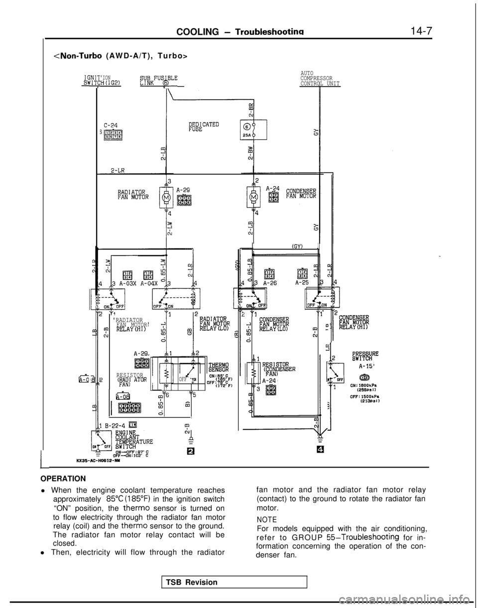
OPERATION l When the engine coolant temperature reaches approximately
85°C (185°F) in the ignition switch
“ON” position, the
therm0 sensor is turned on
to flow electricity through the radiator fan motor relay (coil) and the
therm0 sensor to the ground.
The radiator fan motor relay contact will be
closed.
l Then, electricity will flow through the radiator fan motor and the radiator fan motor relay
(contact) to the ground to rotate the radiator fan
motor.
NOTE
For models equipped with the air conditioning,
refer to GROUP
55-Troubleshooting for in-
formation concerning the operation of the con-
denser fan.
TSB Revision
Page 561 of 1273
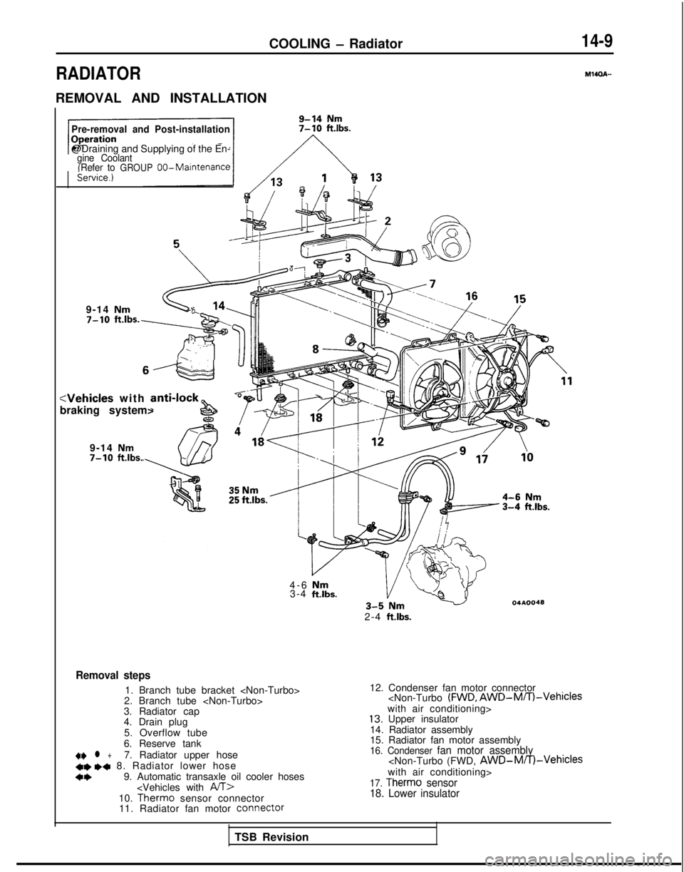
COOLING - Radiator
RADIATOR
REMOVAL AND INSTALLATION
14-9
M14OA-
Pre-removal and Post-installation
@Draining and Supplying of the En-gine Coolant
(Refer toGROUP 00-Maintenancekervice.)
9-14 Nm
(j/-&j
:Vehicles with anti-lock&
braking system>
9-14
Nm7-10 ft.lbs.
4-6 Nm3-4 ftlbs.04AOO48
2-4 ft.lbs.
Removal steps
1. Branch tube bracket
2. Branch tube
3. Radiator cap
4. Drain plug
5. Overflow tube
6. Reserve tank
41) l +7. Radiator upper hose+e ,+ 8. Radiator lower hose
a+9. Automatic transaxle oil cooler hoses
sensor connector
11. Radiator fan motor COnneCtOr12. Condenser fan motor connector
14. Radiator assembly
15. Radiator fan motor assembly
16. Condenser fan motor assembly
18. Lower insulator
TSB Revision
Page 567 of 1273
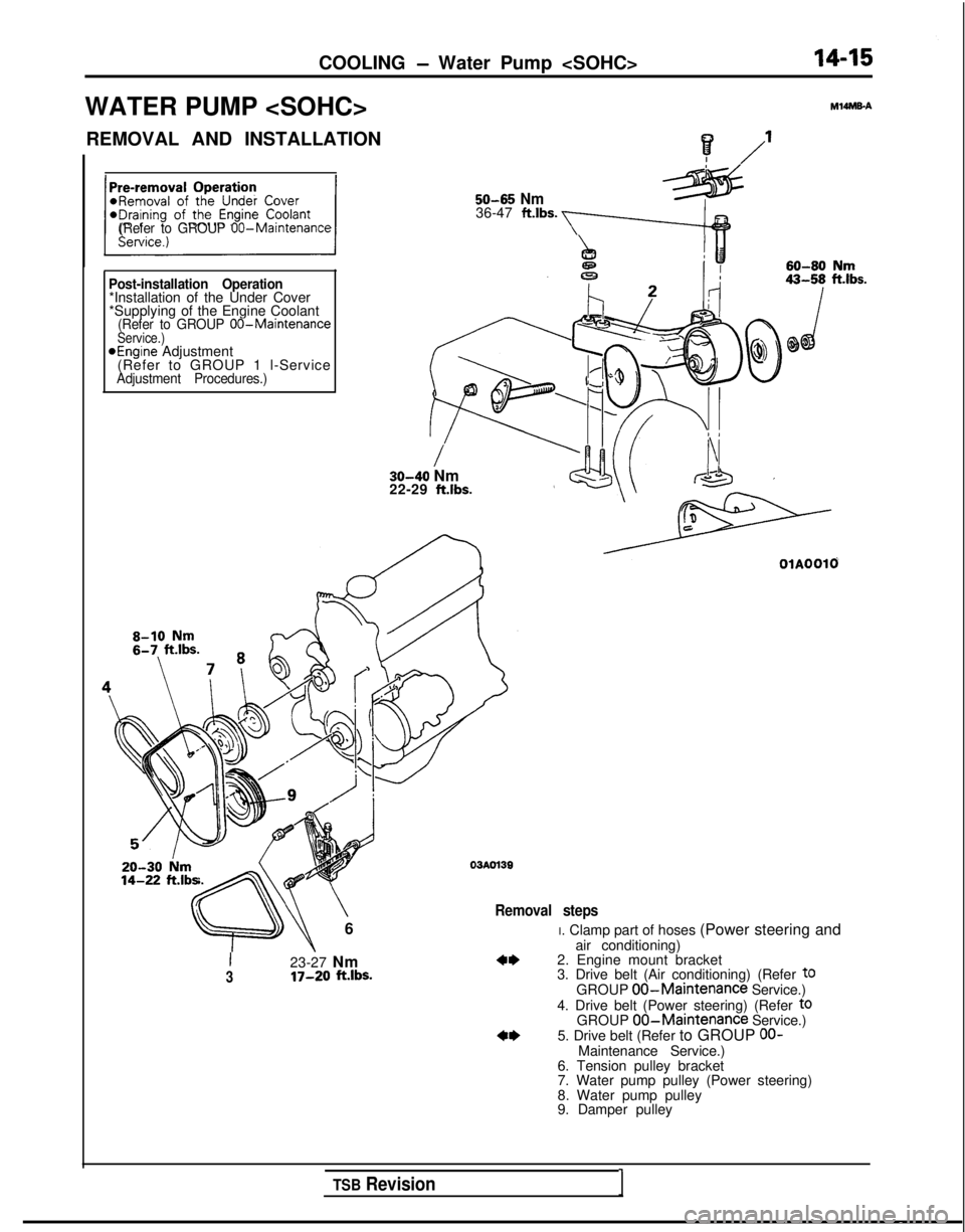
COOLING - Water Pump
WATER PUMP
M14MEA
? /’I
50-65 Nm36-47 ft.lbs. a(Refer to GROUP 00-Maintenance
Post-installation Operation*Installation of the Under Cover
*Supplying of the Engine Coolant
(Refer to GROUP 00-MaintenanceService.)aEngine Adjustment
(Refer to GROUP 1 l-Service
Adjustment Procedures.)
/30-40 Nm
22-29 ft.lbs. 14-22
ft.lb=
\
6
03AOl39
Removal steps
I23-27 Nm3IT-20 ft.lbs.
OlAOOlO
I. Clamp part of hoses (Power steering and
air conditioning)
2. Engine mount bracket
3. Drive belt (Air conditioning) (Refer
t0GROUP 00-Maintenance Service.)
4. Drive belt (Power steering) (Refer toGROUP 00-Maintenance Service.)
5. Drive belt (Refer to GROUP OO-Maintenance Service.)
6. Tension pulley bracket
7. Water pump pulley (Power steering)
8. Water pump pulley
9. Damper pulley
TSB Revision1