belt MITSUBISHI GALANT 1989 Service Manual PDF
[x] Cancel search | Manufacturer: MITSUBISHI, Model Year: 1989, Model line: GALANT, Model: MITSUBISHI GALANT 1989Pages: 1273, PDF Size: 37.62 MB
Page 557 of 1273
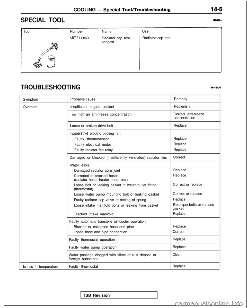
COOLING - Special TooVTroubleshooting
SPECIAL TOOL
1 Tool
Number
Name1 Use
MIT21 0863Radiator cap test Radiator cap test
TROUBLESHOOTINGM14EAAI
Symptom
Overheat Probable cause
Insufficient engine coolant
Too high an anti-freeze concentration Remedy
Replenish
Correct anti-freeze
concentration
Loose or broken drive belt
Replace Inoperative
electric cooling fan
Faulty thermosensor Replace
Faulty electrical motor
Replace
Faulty radiator fan relayReplace
Damaged or blocked (insufficiently ventilated) radiator fins Correct
Water leaks Damaged radiator core joint
Replace
Corroded or cracked hosesReplace
(radiator hose, heater hose, etc.)
Loose bolt or leaking gasket in water outlet fitting
(thermostat)
Loose water pump mounting bolt or leaking gasket
Faulty radiator cap valve or setting of spring
Loose intake manifold bolts or leaking from gasket
Cracked intake manifold
Faulty automatic transaxle oil cooler operation Blocked or collapsed hose and pipe
Loose hose and pipe connection
Faulty thermostat operation
Faulty water pump operation
Water passage clogged with slime or rust deposit or
foreign substance Correct or replace
Correct or replace
Replace
Retorque bolts or replace
gasket
Replace
Replace
Correct
Replace
Replace
Clean
Jo rise in temperature Faulty thermostatReplace
TSB Revision
Page 567 of 1273
COOLING - Water Pump
WATER PUMP
M14MEA
? /’I
50-65 Nm36-47 ft.lbs. a(Refer to GROUP 00-Maintenance
Post-installation Operation*Installation of the Under Cover
*Supplying of the Engine Coolant
(Refer to GROUP 00-MaintenanceService.)aEngine Adjustment
(Refer to GROUP 1 l-Service
Adjustment Procedures.)
/30-40 Nm
22-29 ft.lbs. 14-22
ft.lb=
\
6
03AOl39
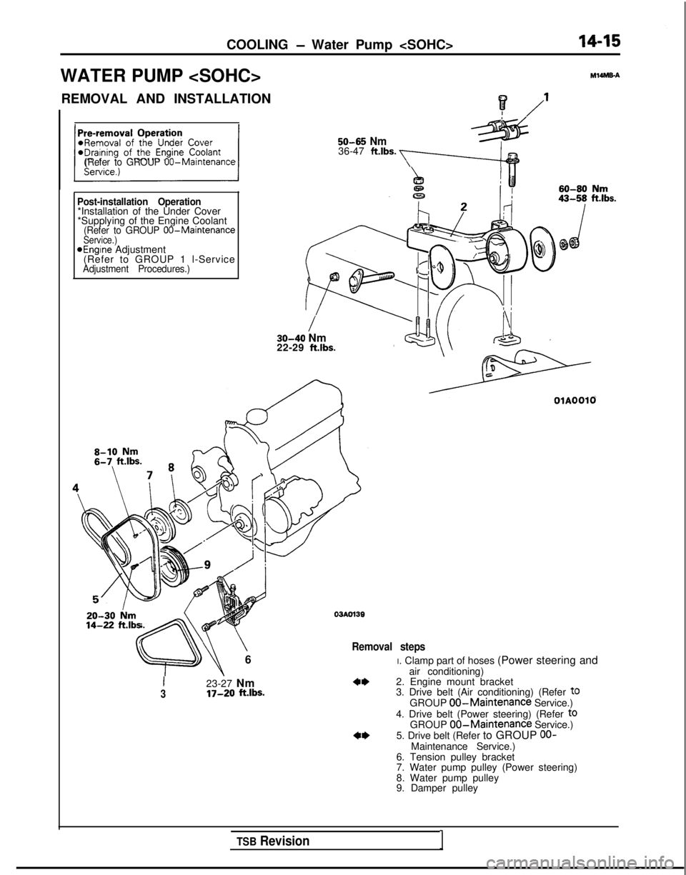
Removal steps
I23-27 Nm3IT-20 ft.lbs.
OlAOOlO
I. Clamp part of hoses (Power steering and
air conditioning)
2. Engine mount bracket
3. Drive belt (Air conditioning) (Refer
t0GROUP 00-Maintenance Service.)
4. Drive belt (Power steering) (Refer toGROUP 00-Maintenance Service.)
5. Drive belt (Refer to GROUP OO-Maintenance Service.)
6. Tension pulley bracket
7. Water pump pulley (Power steering)
8. Water pump pulley
9. Damper pulley
TSB Revision1
Page 568 of 1273
14-16
COOLING - Water Pump
5-7 N
m
/
4-5
ftlbs.
1420-27 Nm
I14-20
ftlbs.
24 ’
\ ‘G\@;&
\“7”f=-is .
In23
ii-16 ftlbs.
i2-15 Nm9- 11 ft.lbs.
03AOWO
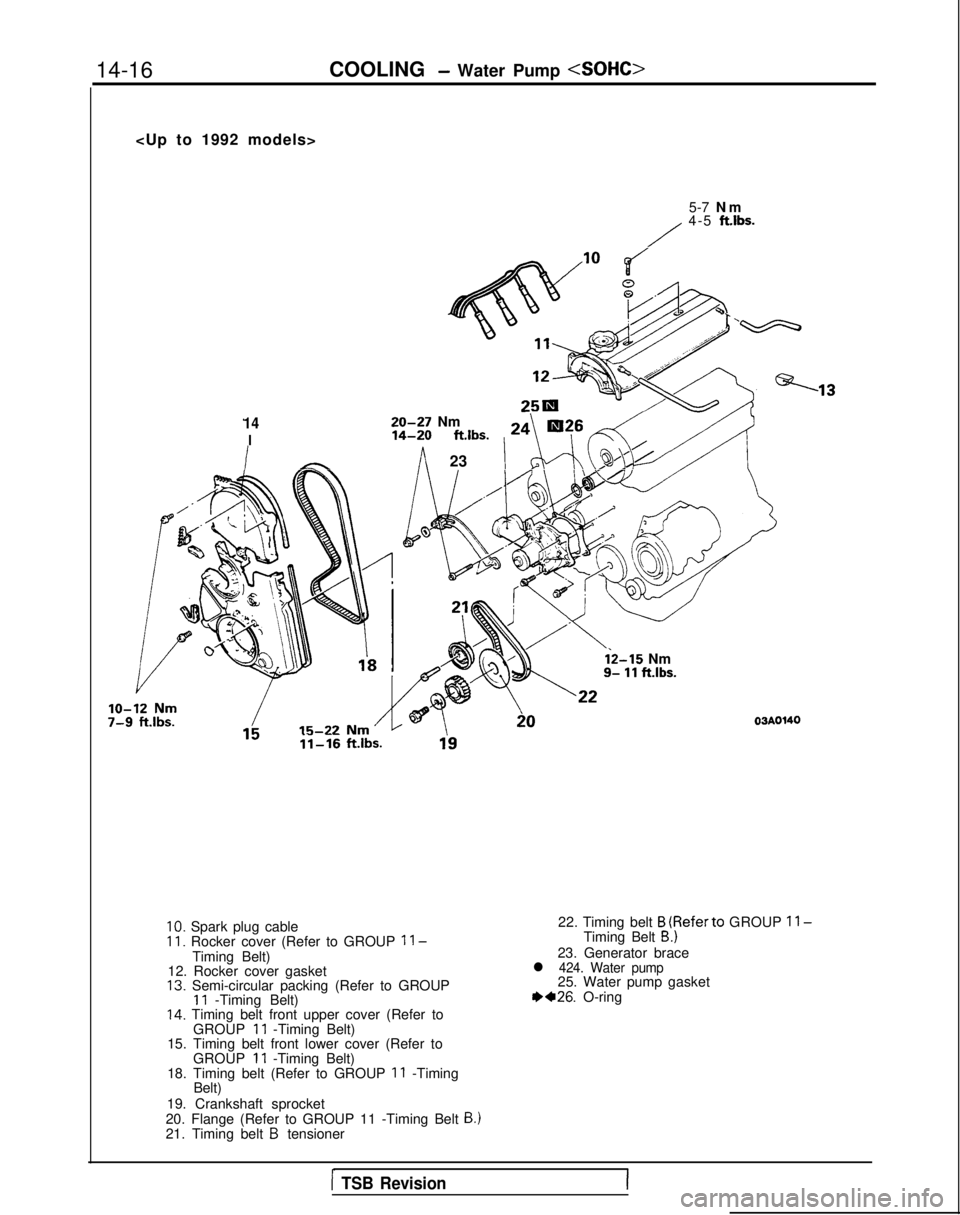
10. Spark plug cableII. Rocker cover (Refer to GROUP ll-Timing Belt)
12. Rocker cover gasket
13. Semi-circular packing (Refer to GROUP11 -Timing Belt)14. Timing belt front upper cover (Refer to
GROUP 11 -Timing Belt) 22. Timing belt
B (Referto GROUP ll-Timing Belt B.)
23. Generator bracel 424. Water pump25. Water pump gasket 1)+26.
O-ring
15. Timing belt front lower cover (Refer to GROUP
11 -Timing Belt)
18. Timing belt (Refer to GROUP 11 -Timing
Belt)
19. Crankshaft sprocket
20. Flange (Refer to GROUP 11 -Timing Belt
B.)21. Timing belt B tensioner
1 TSB Revision
Page 569 of 1273

COOLING - Water Pump
10-7-
9
Cl993 models>
43-55 Nm31-40 ftlbs.
\
20-27 Nm14-20 ftlbs.
3-3.5 NmI
2.2-2.5 ftlbs.
y
12 Nm ftlbs.
i,4-2Oft.l;~
Nrn’x@<,I 1-16 ft.lbs.,
OlAO675
I110-130 Nm80-94 ft.lbs.
11. Rocker cover (Refer to GROUP
11 -Timing Belt.)
12. Rocker cover gasket
14. Timing belt front upper cover (Refer to
GROUP
11 -Timing Belt.)
15. Timing belt front lower cover (Refer to GROUP
11 -Timing Belt.)
16. Automatic tensioner (Refer to GROUP
11 -Timing Belt.)17. Tension pulley
18. Timing belt (Refer to GROUP 11 -Timing
Belt.)
20. Flange (Refer to GROUP 11 -Timing Belt
B.121. Timing belt B tensioner22. Timing belt B (Refer to GROUP11 -Timing Belt B.)23. Generator brace+424. Water pump
25. Water pump gasket
++26. O-ring
19. Crankshaft sprocket
1 TSB Revision
Page 570 of 1273
14-18COOLING - Water Pump
Quality canvas Core wire
\\Adhesive rubber
\Rib rubberlCOO29
W
ater pump
J--iLi+
O-ring
W
ater pipe
I I
SERVICE POINTS OF REMOVALMl4MCAK
2. REMOVAL OF ENGINE MOUNT BRACKET
(1) Place a wooden block at the oil pan part of the engine, and
then jack up the vehicle.
Caution
Jack up carefully,
so as not to apply a load to each part.
(2) Remove the engine mount bracket.
5. REMOVAL OF DRIVE BELT Before removing the V-ribbed belt, loosen the water pump
pulley installation bolt.
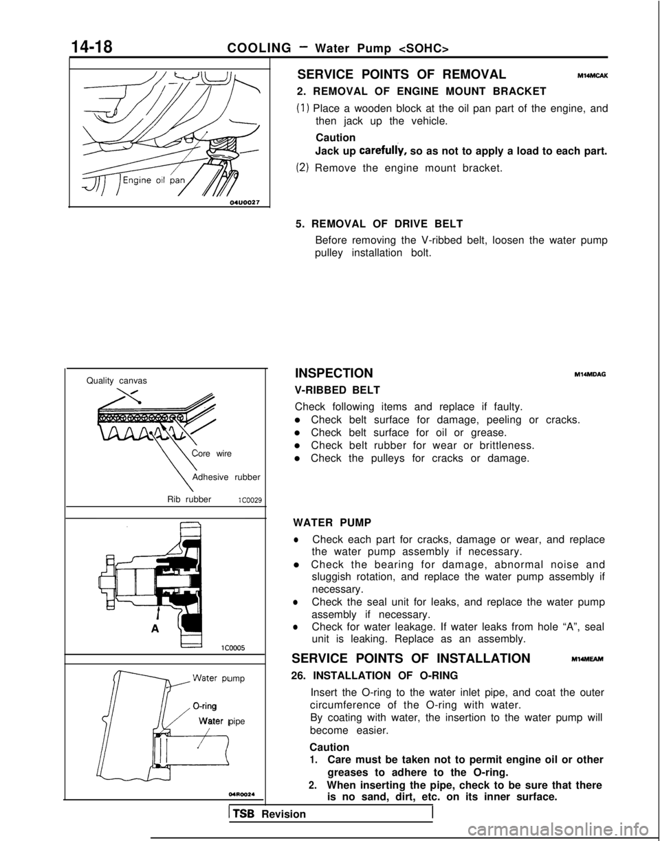
INSPECTION
V-RIBBED BELT
M14MDAG
Check following items and replace if faulty.
l Check belt surface for damage, peeling or cracks.
l Check belt surface for oil or grease.
l Check belt rubber for wear or brittleness.
l Check the pulleys for cracks or damage.
WATER PUMP
lCheck each part for cracks, damage or wear, and replace
the water pump assembly if necessary.
l Check the bearing for damage, abnormal noise and sluggish rotation, and replace the water pump assembly if
necessary.
lCheck the seal unit for leaks, and replace the water pump
assembly if necessary.
lCheck for water leakage. If water leaks from hole “A”, seal
unit is leaking. Replace as an assembly.
SERVICE POINTS OF INSTALLATION
Ml4MEAm
26. INSTALLATION OF O-RING Insert the O-ring to the water inlet pipe, and coat the outer
circumference of the O-ring with water. By coating with water, the insertion to the water pump will
become easier.
Caution
1.Care must be taken not to permit engine oil or other
greases to adhere to the O-ring.
2.When inserting the pipe, check to be sure that there is no sand, dirt, etc. on its inner surface.
1 TSB Revision
Page 572 of 1273
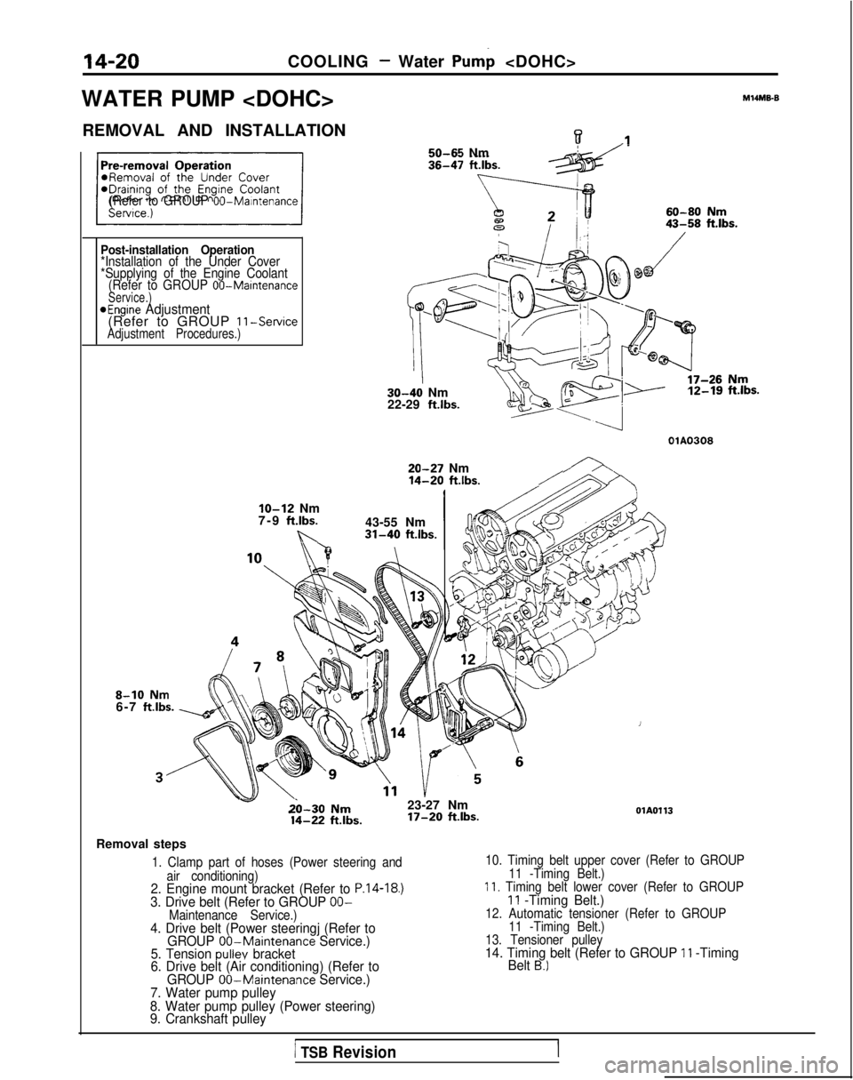
14-20COOLING - Water Pump
WATER PUMP
M14ME6
REMOVAL AND INSTALLATIONw.I50-65 Nm
(Refer to GROUP 00-Maintenance
Post-installation Operation*Installation of the Under Cover
*Supplying of the Engine Coolant (Refer to GROUP
00-MaintenanceService.)aEngine Adjustment(Refer to GROUP 11-ServiceAdjustment Procedures.)
30-40 Nm
22-29 ft.lbs. 12-19
ft.lbs.
OlA0308
20-27 Nm14-20 ft.lbs./
8-10 Nm6-7 ftlbs.
IO-12 Nm
7-9 ft.lbs.
b..
43-55 Nm31-40 ft.lbs.
v&l-30 Nm23-27 Nm 14-22
ftlbs. 17-20
ft.lbs.OlA0113
Removal steps
1. Clamp part of hoses (Power steering and
air conditioning)
2. Engine mount bracket (Refer to P.14-18.)3. Drive belt (Refer to GROUP OO-Maintenance Service.)4. Drive belt (Power steeringj (Refer to GROUP 00-Maintenance Service.)
5. Tension pullev bracket
6. Drive belt (Air conditioning) (Refer to
10. Timing belt upper cover (Refer to GROUP
11 -Timing Belt.)
11. Timing belt lower cover (Refer to GROUP11 -Timing Belt.)12. Automatic tensioner (Refer to GROUP11 -Timing Belt.)
13. Tensioner pulley
14. Timing belt (Refer to GROUP 11 -Timing
Belt B.)
GROUP 00-Maintenance Service.)
7. Water pump pulley
8. Water pump pulley (Power steering)
9. Crankshaft pulley
1 TSB RevisionI
Page 573 of 1273

COOLING- Water Pump
15. Crankshaft sprocket
15. Crankshaft sprocket16. Flange (Refer to GROUP 11 -Timing Belt
16. Flange (Refer to GROUP 11 -Timing Belt
B.)B.)17. Timing belt B tensioner
17. Timing belt B tensioner18. Timing belt B (Refer to GROUPII-Timing Belt B.)
19. Generator brace*4 20. Water pump.,.
21. Water pump gasketC.’
22. O-ring (Refer to P.14-18.).‘* .
18. Timing belt B (Refer to GROUPll-Timing Belt B.)
19. Generator brace*4 20. Water pump.,.
21. Water pump gasketC.’
22. O-ring (Refer to P.14-18.).‘* 1
TSB RevisionTSB Revision
20-27 14-20
olAol4
Page 574 of 1273

14-22COOLING - Water Pump
ldeniification mark
Generator brace INSPECTION
V-RIBBED BELT Refer to
P.14-18.
Ml4mDAN
WATER PUMP
0Check each part for cracks, damage or wear, and replace
the water pump assembly if necessary.
l Check the bearing for damage, abnormal noise and
sluggish rotation, and replace the water pump assembly ifnecessary.
l Check the seal unit for leaks, and replace the water pump
assembly if necessary.
l Check for water leakage.
SERVICE POINTS OF INSTALLATION
MMMEAU
20. INSTALLATION OF WATER PUMP
(1) Clean both gasket surfaces of water pump body and cylinder block.
(2) Install new water pump gasket and water pump assembly and tighten the bolts.
No, identification Bolt diameter (d)mark x length (4) mm (in.)NmT”iptK.)
148 x 14 (.31 x ,551
248 x 22 (.31
x ,87112-15 (9-10)
348
x 30 t.31 x 1.18)
478x
65(.31 x2.56)20-27(15-l 9)
5
48 x28(.31
x1.10)12-15
(9-10)
TSB Revision
Page 1261 of 1273
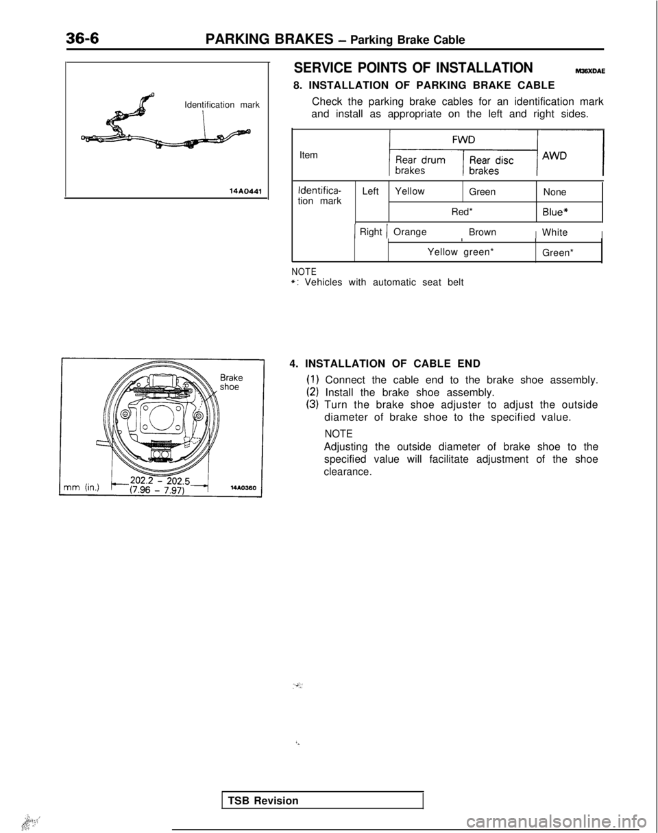
36-6PARKING BRAKES - Parking Brake Cable
Identification mark
14A0441
SERVICE POINTS OF INSTALLATIONWXDAE
8. INSTALLATION OF PARKING BRAKE CABLE Check the parking brake cables for an identification mark
and install as appropriate on the left and right sides.
Item Identifica-
tion mark Left
Yellow
Green None
Red*
Blue*
1 Right 1 Orange BrownIWhiteI I
Yellow green* I
Green*
NOTE*: Vehicles with automatic seat belt
4. INSTALLATION OF CABLE END
(1) Connect the cable end to the brake shoe assembly.
(2) Install the brake shoe assembly.
(3) Turn the brake shoe adjuster to adjust the outside diameter of brake shoe to the specified value.
NOTE
Adjusting the outside diameter of brake shoe to thespecified value will facilitate adjustment of the shoe
clearance. .‘,,
I.**i:,1;q ,.’
TSB Revision
Page 1262 of 1273
ALPHABETICAL INDEX1
A
ABS
Checking by the ABS Warnrng Light................
. 35-68-l
Troubleshooting ...........................
35-l 5-l
ABS POWER RELAY, Chec
k 35-74-l
ACCELERATOR CABLE
Inspection and Adjustment
13-398-l
Inspection and Adjustment
ACCELERATOR SWITCH, Inspection and Adjustment 13-329-I
A/C COMPRESSOR CLUTCH RELAY
On-vehicle Inspection
.............
. 13-285-l
On-vehrcle
Inspection
. 13-83-t
On-vehicle Inspection
. 13-176-l
ACTIVE-ECS ON-BOARD DIAGNOSTIC, Check......
. 338-88-I
ACTIVE-ECS RELAY.......................
. 338-141
-I
ACTIVE-ECS SENSOR....
.
...... ............ 338-138-I
ACTIVE-ECS SYSTEM
Checking by Using Alarm Light
.................
. 338-87-I
Operation Check ........................... 338-90-I
AERO PARTS..
.
........................... 51-18-l
AIR CLEANER...............................
. 15-9-I
AIR CLEANER ELEMENT
Inspection and Replacement
....................
. 15-6-l
Maintenance .......................... 00-39-l
AIR COMPRESSOR..........................
. 338-125-I
AIR CONDITIONING SWITCH
Emission control
...........................
.
17-21 -I
Heater, Air
Conditionrng
and Ventilation .............. 55-29-l
On-vehicle Inspection
On-vehicle Inspection
. 13-83-l
On-vehicle Inspection
. 13-176-l
AIR TUBE..............
.
....................... 338-133-I
ALARM LIGHT, Check. ......................... 338-87-I
ALARM SYSTEM, Theft ..........................
54-165-11
ALIGNMENT
Front Wheel, Adjustment .......................
. 33A-5-l
Rear
Wheel, inspection
. 34-23-l
Rear Wheel, Inspection
. 34-5-l
ANTENNA ......................................
54-153-11
ANTI-LOCK BRAKING SYSTEM, Troubleshooting .........
.
35-15-1
ARM
Lower
. 338-103-I
Lower
.
33A-10-I
Lower
................... 34-28-l
Torsion
.
338-l 19-l
Torsion
...................34-l 5-lTrailing
................. 34-31-l
Upper
.................. 34-28-l
AUDIO
SYSTEM................
.
.................
54-l 12-11
AUTO-CRUISE CONTROL. ..........................
. 13-408-I
AUTO-CRUISE CONTROL INDIVIDUAL PARTS, inspection..
. 13-401-I
AUTO-CRUISE CONTROL SYSTEM...................
. 13-332-l
AUTO-CRUISE CONTROL SYSTEM, Inspection..........
. 13-397-l
AUTOMATIC TRANSAXLE, Maintenance ................. 00-43-I
AXLE
Rear, Maintenance
...............................
. 00-45-I
Torsion
.
338-l 19-l
Torsion
.
......................... 34-15-l
AXLE HUB
Rear
Rear CFWD-Rear
Drum Brakes> ................... 27-6-l
AXLE SHAFT
.
27-17-1
B
BACKLASH. Total, Rear Axle, Check
. 27-15-l
BALL JOINT
Rotation Starting Torque Check ...................... 378-8-I
Tie Rod End, Staning Torque Check .................. 37A-15-l
Tie Rod End, Variation Check ....................... 37A-15-l
BALL JOINT SEALS, Maintenance ..................... 00-45-I
BAR
Stabilizer
. 338-106-I
Stabilizer
. 33A-13-l
Stabilizer
. 34-37-l
BAROMETRIC PRESSURE SENSOR
On-vehicle Inspection
................
. 13-266-l
On-vehicle Inspection
On-vehicle Inspection
. 13-154-l
BASIC IDLE SPEED
Adjustment
...........................
. 13-245-l
Adjustment
Adjustment
. 13-133-l
BATTERY.........................................
.
54-2-11
BATTERY, Flat Remedy.
.............................
. 35-75-l
BEARING
Wheel, Adjustment
. 338-87-I
Wheel, Adjustment
BELT
Drive, Compressor, Adjustment
....................
. 55-17-l
Drive (For Water Pump and Generator), Maintenance ..... 00-41-I
Drive, Tension Adjustment
Drive, Tension Adjustment
Seat..........................................
. 52-39-l
Timing
Timing
. 11-34-l
Timing, Maintenance ............................... 00-40-I
Timing, Tension Adjustment
BLEEDING
Clutch
..........................................
. 21-6-l
4ws...........................................
. 370-4-I
Service Brakes. .................................. 35-57-l
Steering ........................................ 37A-22-l
BLOWER..........................................
. 55-32-l
BOOSTER
Brake
.........................................
. 35-85-l
Brake, Operating Inspection ......................... 35-54-l
BOOST METER, On-vehicle Inspection
BOOTS, Drive Shaft, Maintenance ....................... 00-45-I
BRAKE
Disc, Front
......................................
. 35-94-l
Disc, Rear.....................................
.
35-l 14-l
BRAKE BOOSTER
...................................
. 35-85-l
BRAKE BOOSTER, Operating Inspection .................. 35-54-l
BRAKE DISC
Front, Run-out Check.
.............................
. 35-63-l
Front, Run-out Correction ........................... 35-64-l
Front, Thickness Check ............................. 35-65-l
Rear, Run-out Check ............................... 35-66-l
Rear, Run-out Correction. ........................... 35-66-l
Rear, Thickness Check............................
. 35-66-l
BRAKE DRUM, tnside
Diameter, Check ................... 35-67-l
BRAKE FLUID LEVEL SENSOR, Check...................
. 35-54-l
BRAKE FLUID PRESSURE SWITCH
AWD-ABS (Up to 1991 Models)
....................
.
35-133-l
AWD-ABS
(Up to 1991 models), Check ...............
. 35-75-l
BRAKE HOSES, Maintenance ........................... 06-45-t
BRAKELINE
........................................
35-87-l