brake fluid MITSUBISHI GALANT 1989 Service Repair Manual
[x] Cancel search | Manufacturer: MITSUBISHI, Model Year: 1989, Model line: GALANT, Model: MITSUBISHI GALANT 1989Pages: 1273, PDF Size: 37.62 MB
Page 6 of 1273
00-4GENERAL - How to Use This Manual
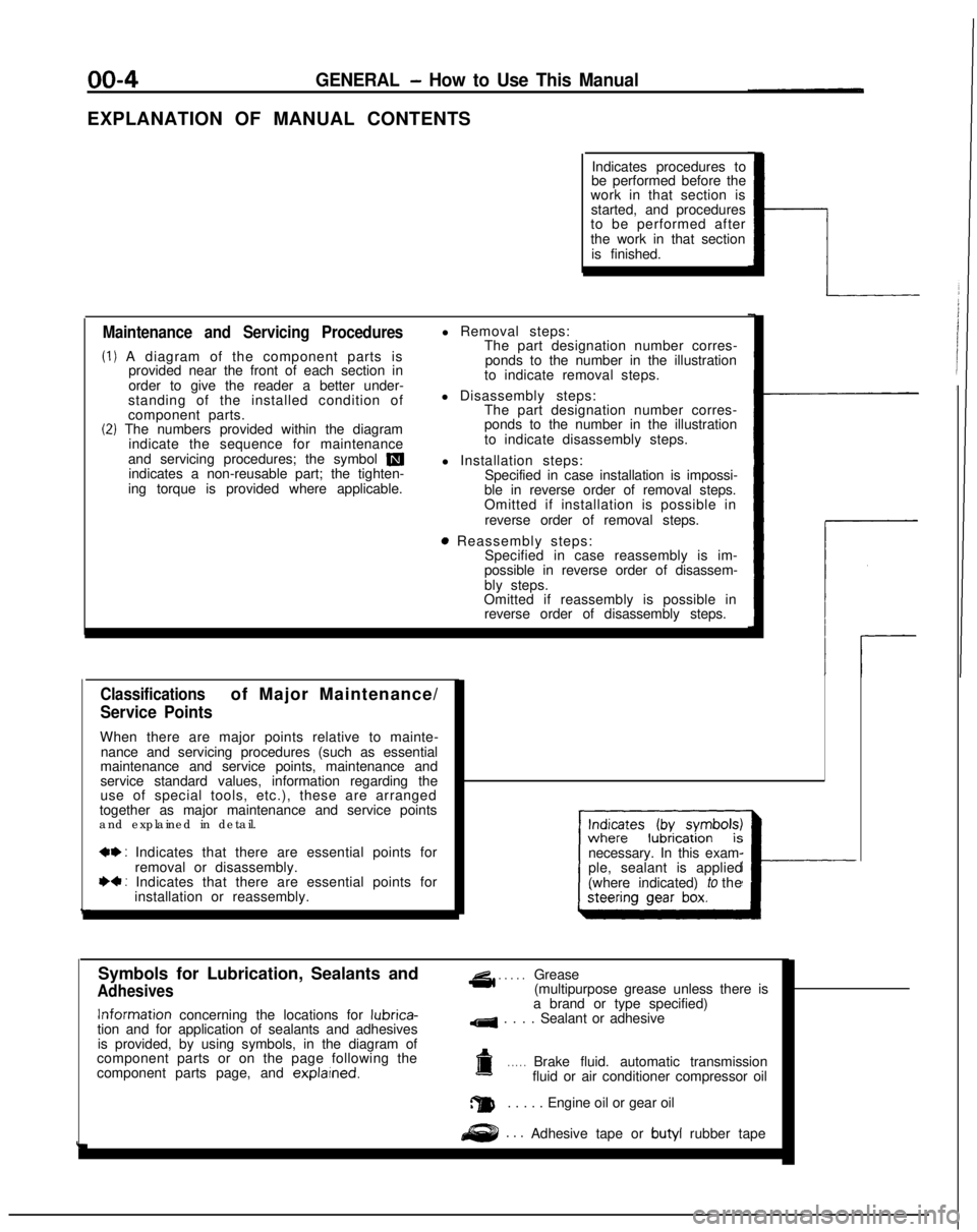
EXPLANATION OF MANUAL CONTENTSIndicates procedures to
be performed before the
work in that section is
started, and procedures
to be performed after
the work in that section
is finished.
Maintenance and Servicing Procedures
(1) A diagram of the component parts is provided near the front of each section in
order to give the reader a better under-
standing of the installed condition of
component parts.
(2) The numbers provided within the diagram indicate the sequence for maintenance
and servicing procedures; the symbol
mindicates a non-reusable part; the tighten-
ing torque is provided where applicable. l Removal steps:
The part designation number corres-
ponds to the number in the illustration
to indicate removal steps.
l Disassembly steps: The part designation number corres-
ponds to the number in the illustration
to indicate disassembly steps.
l Installation steps: Specified in case installation is impossi-
ble in reverse order of removal steps.
Omitted if installation is possible in
reverse order of removal steps.
8 Reassembly steps: Specified in case reassembly is im-
possible in reverse order of disassem-
bly steps.
Omitted if reassembly is possible in reverse order of disassembly steps.
Classificationsof Major Maintenance/
Service Points
When there are major points relative to mainte-
nance and servicing procedures (such as essential
maintenance and service points, maintenance and
service standard values, information regarding the
use of special tools, etc.), these are arranged
together as major maintenance and service points
and explained in detail.
*+ : Indicates that there are essential points for
removal or disassembly.
I)+ : Indicates that there are essential points forinstallation or reassembly. necessary. In this exam-
ple, sealant is applied
(where indicated) to the
I---
Symbols for Lubrication, Sealants and
Adhesives
4 . . . . .Grease
(multipurpose grease unless there is Information
concerning the locations for lubrica-
tion and for application of sealants and adhesives
is provided, by using symbols, in the diagram of
component parts or on the page following the
component parts page, and explarned.
a brand or type specified)
4 . . . . Sealant or adhesive
a. . . . .Brake fluid. automatic transmission
fluid or air conditioner compressor oil
a. . . . . Engine oil or gear oil
. . .Adhesive tape or butyl
rubber tape
Page 32 of 1273
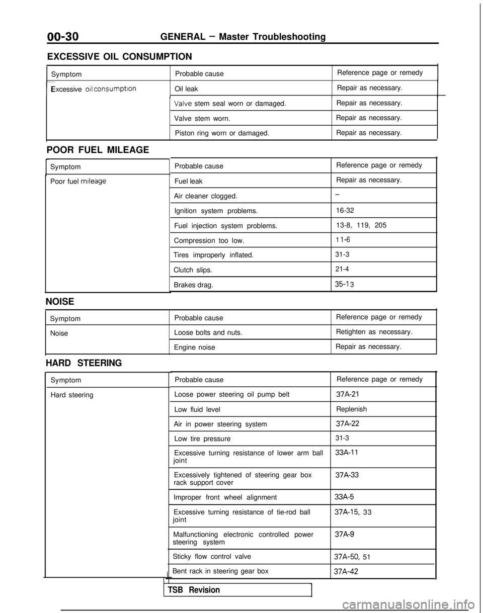
00-30GENERAL - Master Troubleshooting
EXCESSIVE OIL CONSUMPTION Symptom Probable cause Reference page or remedy
1
r-Excessive 011 consumption
Oil leak Repair as necessary.I Valve
stem seal worn or damaged. Repair as necessary.
Valve stem worn. Repair as necessary.
Piston ring worn or damaged. Repair as necessary.
POOR FUEL MILEAGE Symptom
Poor fuel mtleage
Probable cause
Fuel leak
Air cleaner clogged. Ignition system problems.
Fuel injection system problems.
Compression too low.
Tires improperly inflated.
Clutch slips.Brakes drag. Reference page or remedy
Repair as necessary.
-
16-32
13-8, 119, 205
1 l-6
31-3 21-4
35-l 3
NOISE
SymptomNoise Probable cause
Loose bolts and nuts.
Engine noise Reference page or remedy
Retighten as necessary.
Repair as necessary.
HARD STEERING
Symptom
Hard steering Probable cause
Reference page or remedy
Loose power steering oil pump belt
37A-21
Low fluid level Replenish
Air in power steering system
37A-22
Low tire pressure31-3
Excessive turning resistance of lower arm ball33A-11
joint Excessively tightened of steering gear box 37A-33
rack support cover
Improper front wheel alignment
Excessive turning resistance of tie-rod ball
joint
Malfunctioning electronic controlled power
steering system
Sticky flow control valve
Bent rack in steering gear box
J
TSB RevisionI
33A-5
37A-15, 33 37A-9
37A-50,
51 37A-42
Page 37 of 1273
GENERAL -Lubrication and Maintenance/Recommended Lubricants and Lubricant Capacities Table00-35
If premium unleaded gasoltne IS not available,
MATERIALS ADDED TO FUEL
unleaded gasoline having a octane rating of 87 or
91 RON (Research Octane Number) may be used. Indiscriminate use of fuel system cleaning agents
In this case, the performance and fuel consumption should be avoided. Many of these materials
in-
WIII suffer a little degradatron.tended for gum and varnish removal may contain
highly active
solvents or similar ingredients that can
be harmful to gasket and diaphragm materials used
in fuel system component parts.
Gasolines containing alcohol
Some gasolrnes sold at service stations contain
alcohol, although they may not be SC identified. Use
of fuels containing alcohol is not recommended
unless the nature of the blend can be
determrned
as being satisfactory.
Gasohol
- A mixture of 10% ethanol (grain alcohol)
and 90% unleaded gasoline may be used
In your
car. If
driveability problems are experienced as a
result of using gasohol, it IS recommended that the
car be operated on gasoline. Methanol
- Do not use gasolines containing
methanol (wood alcohol). Use of this type of
alcohol can result in vehicle performance deteriora-
tion and damage critical parts in the fuel system
components. Fuel system damage and performance
problems, resulting from the use of gasolines
containing methanol, may not be covered by the
new car warranty.
Gasolines containing MTBE (Methyl Tertiary Butyl
Ether)
Unleaded gasolrne containrng
15% or less MTBE
may be used in your car. (Fuel containing MTBE
over 15% vol. may cause reduced engine per-
formance and produce vapor lock or hard starting.) RECOMMENDED
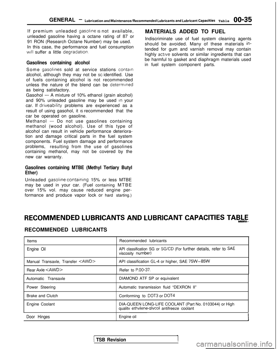
LUBRICANTS AND
LUBRICANT CAPACITIES TAB,&-
RECOMMENDED LUBRICANTS
Items
Engine Oil
Recommended lubricants
API classification SG or SGKD (For further details, refer to SAEviscosity number)
Manual Transaxle, Transfer
Rear Axle
API classification GL-4 or higher, SAE 75W-85W
Refer to P.OO-37.
Automatic Transaxle
Power Steering
Brake and Clutch
Engine Coolant DIAMOND ATF SP or equivalent
Automatic transmission fluid “DEXRON II” Conforming to
DOT3 or DOT4
DIA-QUEEN LONG-LIFE COOLANT (Part No. 0103044) or High
qualitv ethvlene-qlvcol
antifreeze coolant
Door HingesEngine oil
1 TSB Revision
Page 40 of 1273
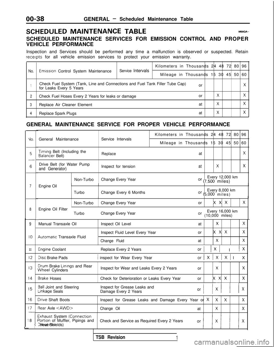
00-38GENERAL- Scheduled Maintenance Table
SCHEDULED MAINTENANCE
TABLEMOOOA-
SCHEDULED MAINTENANCE SERVICES FOR EMISSION CONTROL AND PROPER
VEHICLE PERFORMANCE
Inspection and Services should be performed any time a malfunction is ob\
served or suspected. Retain receipts
for all vehicle emission services to protect your emission warranty.
Kilometers in Thousands 24 48 72 80 96
No.Emwsron Control System MaintenanceService IntervalsMileage in Thousands 15 30 45 50 60
1Check Fuel System (Tank, Line and Connections and Fuel Tank Filler Tube\
Cap) orXfor Leaks Every 5 Years
2Check Fuel Hoses Every 2 Years for leaks or damage orXX
3Replace Air Cleaner ElementatXX
4Replace Spark PlugsatXX
GENERAL MAINTENANCE SERVICE FOR PROPER VEHICLE PERFORMANCE
L
1
1
1
1
1
i
IO.General Maintenance
Service Intervals
7Engine Oil
8
9
IO
III2
I3
14
15
I6
I71
8
L
I
I
I
I
I\
I
II
I
I
;(
Kilometers in Thousands 24 48 72 80 96
Mileage in Thousands 15 30 45 50 60 Timing
Belt (Including the Balancer
Belt)
ReplaceatX
Drive Belt (for Water Pump
Inspect for tensionatXXand Generator)
Non-TurboChange Every Year Every 12,000 kmOr (7,500 miles)
Turbo Change Every 6 Months Every 8,000 km
Or (5.000 miles
)
II
Non-Turbo
Change Every Year or X X XX
Every 16,000 kmOr (10,000 miles)
Engine Oil Filter
TurboChange Every Year
Manual Transaxle Oil 4utomatrc
Transaxle Fluid Inspect Oil Level
at
XX
Inspect Fluid Level Every Yearor X X XX
Change FluidatXX
Engine Coolant
Replace Every 2 YearsOrI 1x1 I IX
Disc Brake Pads1 inspect for Wear Every Yearor/XlXlXl I
X
3rum
Brake Linings
and Rear iNheel
Cylinders Inspect for Wear and Leaks Every 2 Years
or
XX
3rake HosesCheck for Deterioration or Leaks Every Year or X X XX
3all Joint and SteeringInspect for Grease Leaks and-inkage
Seals
Damage Every 2 Years
Or I/ XII x
Irive Shaft Boots Inspect for Grease Leaks and Damage Every Year or XXXX
3ear Axle
Exhaust System (Connectron>ortion of Muffler, Pipings and
Check and Service as Required Every 2 YearsConverter Heat Shields)
TSB Revision1
Page 46 of 1273
GENERAL -Maintenance Service
(1O)Star-t engine and allow to idle for at least two minutes.
Then, with parking brake on, move selector
fever
momentarily to each position, ending in “N” Neutral
position.
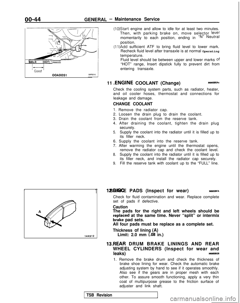
(11)Add sufficient ATF to bring fluid level to lower mark.
Recheck fluid level after transaxle is at normal Operating
temperature. Fluid level should be between upper and lower marks of
“HOT” range, Insert dipstick fully to prevent dirt from
entering transaxle.
OOA0051
11 .ENGINE
COOLANT (Change)MOOSEEAC
Check the cooling system parts, such as radiator, heater,
and oil cooler hoses, thermostat and connections for
leakage and damage.
CHANGE COOLANT
1. Remove the radiator cap.
2. Loosen the drain plug to drain the coolant.
3. Drain the coolant from the reserve tank.
4. After draining the coolant, tighten the drain plug securely.
5.Supply the coolant into the radiator until it is filled up to
its filler neck.
6. Supply the coolant into the reserve tank.
7. After warming the engine until the thermostat opens, remove the radiator cap and check the coolant level.
8.Supply the coolant into the radiator until it is filled up to
its filler neck, and install the radiator cap securely.
9.Fill the reserve tank with coolant up to the “FULL” line.
14K512
1 12.DISC BRAKE PADS (Inspect for wear) MWSBFA
Check for fluid contamination and wear. Replace complete
set of pads if defective.
Caution
The pads for the right and left wheels should be
reDlaced at the same time. Never “split” or intermix
brkke pad sets.
All four pads must be replace as a complete set.
Thickness of lining (A)
Limit: 2.0 mm (.08 in.)
13.REAR DRUM BRAKE LININGS AND REAR
WHEEL CYLINDERS (Inspect for wear and
leaks)MOOSBGB
1. Remove the brake drum and check the thickness of brake shoe lining for wear. Check the automatic brake
adjusting system by hand to see if it operates smoothly.
Also see if the gears are in proper mesh with each
other. To assure smooth functioning, apply a very thin
coat of multipurpose grease to the friction surface of
adjuster and link shaft.
TSB Revision1
Page 47 of 1273
14KO24
OOA0186
GENERAL - Maintenance Service00-45
2.Inspect the wheel cylinder boots for evidence of a brake
fluid leak. Visually check the boots for cuts, tears or heat cracks. (A slight amount of fluid on the boot may
not be a leak, but may be preservative fluid used at
assembly.)
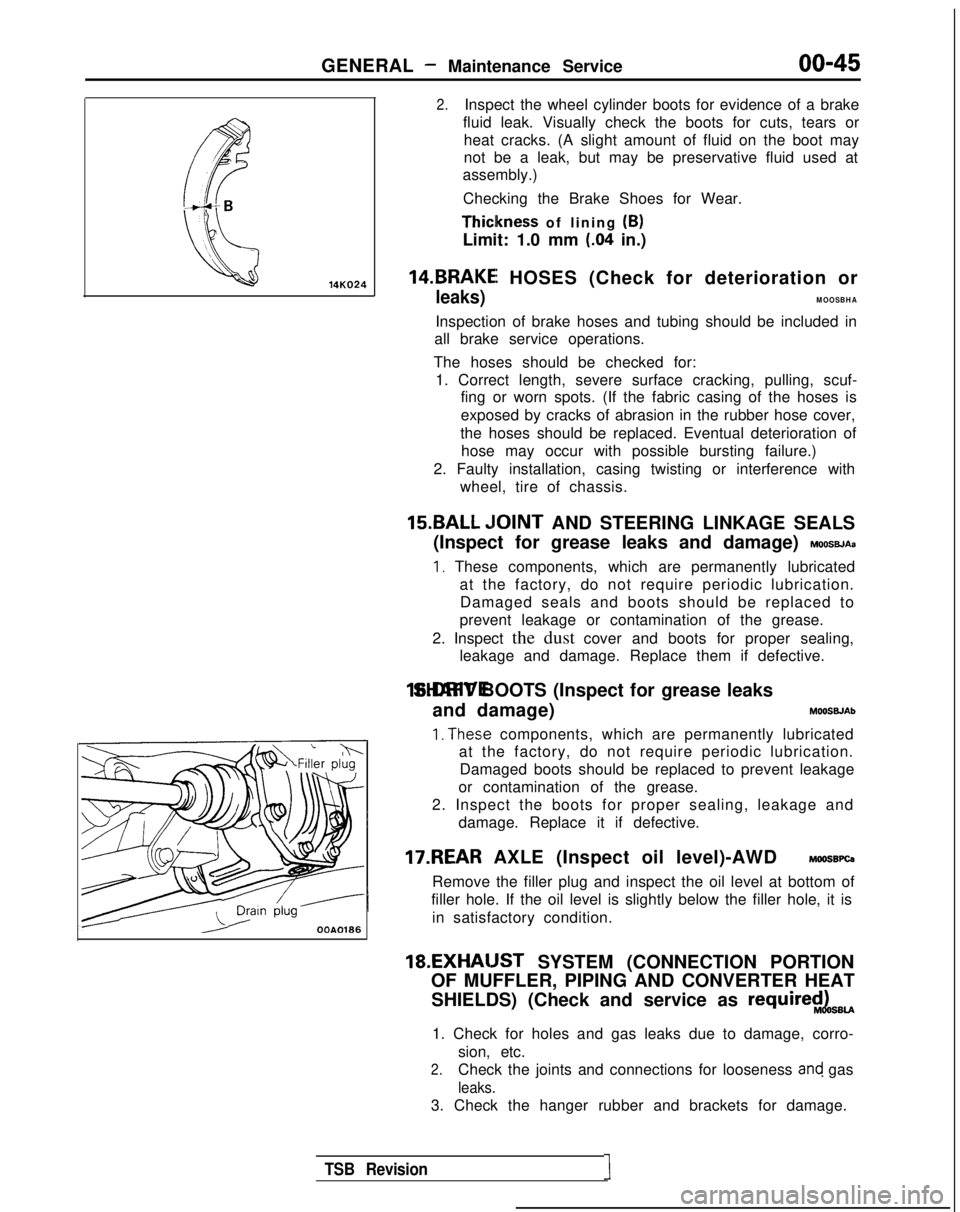
Checking the Brake Shoes for Wear. Thiclkness
of lining (B)
Limit: 1.0 mm
(.04 in.)
14.BRAKEI HOSES (Check for deterioration or
leaks)MOOSBHA
Inspection of brake hoses and tubing should be included in
all brake service operations.
The hoses should be checked for: 1. Correct length, severe surface cracking, pulling, scuf- fing or worn spots. (If the fabric casing of the hoses is
exposed by cracks of abrasion in the rubber hose cover,
the hoses should be replaced. Eventual deterioration of hose may occur with possible bursting failure.)
2. Faulty installation, casing twisting or interference with wheel, tire of chassis.
15.BALL ,IOINT AND STEERING LINKAGE SEALS
(Inspect for grease leaks and damage)
MOOSBJAa
I, These components, which are permanently lubricated at the factory, do not require periodic lubrication.Damaged seals and boots should be replaced to
prevent leakage or contamination of the grease.
2. Inspect the dust cover and boots for proper sealing, leakage and damage. Replace them if defective. 16.DRIVE SHAFT BOOTS (Inspect for grease leaks
and damage) MOOSWAb
1. The.se components, which are permanently lubricated
at the factory, do not require periodic lubrication.
Damaged boots should be replaced to prevent leakage
or contamination of the grease.
2. Inspect the boots for proper sealing, leakage and damage. Replace it if defective.
17.REAR AXLE (Inspect oil level)-AWD MOOSBPQ
Remove the filler plug and inspect the oil level at bottom of
filler hole. If the oil level is slightly below the filler hole, it is
in satisfactory condition. 18.EXHAIJST
SYSTEM (CONNECTION PORTION
OF MUFFLER, PIPING AND CONVERTER HEAT
SHIELDS) (Check and service as
require$LsBU
1. Check for holes and gas leaks due to damage, corro- sion, etc.
2.Check the joints and connections for looseness and gas
leaks.
3. Check the hanger rubber and brackets for damage.
TSB Revision1
Page 656 of 1273
21-6CLUTCH - Service Adjustment Procedures
5.If the clutch pedal free play and the distance between the
clutch pedal and the firewall when the clutch is disengaged
do not agree with the standard values, it is probably the
result of either air in the hydraulic system or a faulty master
cylinder or clutch. Bleed the air, or disassemble and inspect
the master cylinder or clutch.
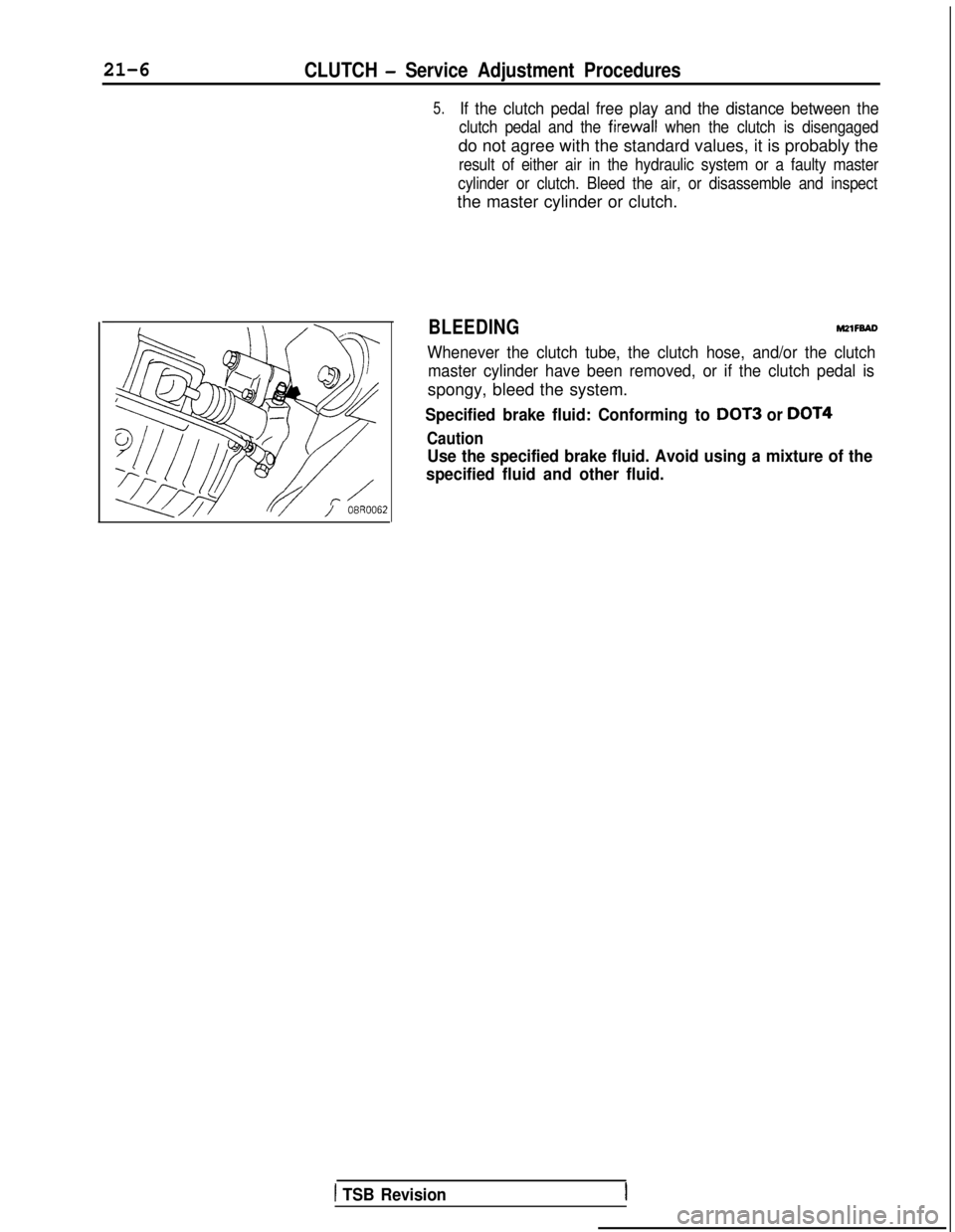
BLEEDINGM2lFBAD
Whenever the clutch tube, the clutch hose, and/or the clutch master cylinder have been removed, or if the clutch pedal is
spongy, bleed the system.
Specified brake fluid: Conforming to DOT3 or DOT4
Caution
Use the specified brake fluid. Avoid using a mixture of the
specified fluid and other fluid.
1 TSB Revision
Page 662 of 1273
21-12CLUTCH - Clutch Master Cylinder
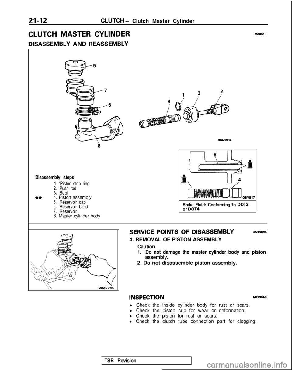
CLUTCH MASTER CYLINDER
DISASSEMBLY AND REASSEMBLY
MZlNA-
Disassembly steps
1. ‘Piston stop ring2.Push rod3.Boot
*I)4. Piston assembly5.Reservoircap6.Reservoirband7.Reservoir8. Master cylinder body
08AOO34
Brake Fluid: Conforming to DOT3or DOT4
SERVICE POINTS OF DISASSEMBLYMZlNBAC
4. REMOVAL OF PISTON ASSEMBLY
Caution
1.Do not damage the master cylinder body and piston
assembly.
2. Do not disassemble piston assembly.
\\08AOOi4
INSPECTIONM21NcAc
l Check the inside cylinder body for rust or scars.
l Check the piston cup for wear or deformation.
l Check the piston for rust or scars.
l Check the clutch tube connection part for clogging.
TSB Revision
Page 728 of 1273
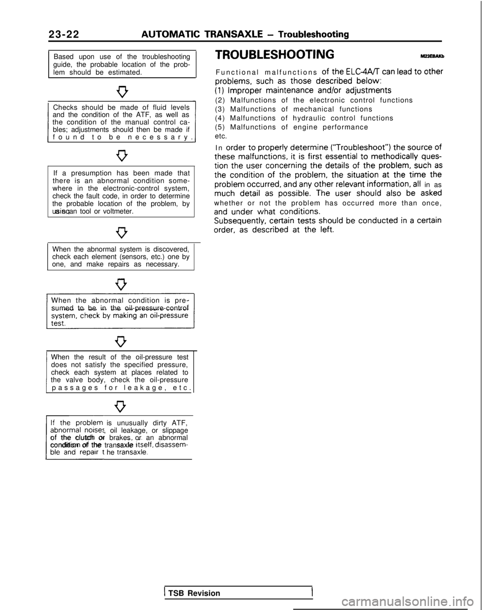
23-22 AUTOMATIC
TRANSAXLE
- Troubleshooting
Based upon use of the troubleshooting
guide, the probable location of the prob-
lem should be estimated.
Checks should be made of fluid levels
and the condition of the ATF, as well as
1 found to be necessary
.
the condition of the manual control ca-
bles; adjustments should then be made if
If a presumption has been made that
there is an abnormal condition some-
where in the electronic-control system,
check the fault code, in order to determine
the probable location of the problem, by using a scan tool or voltmeter.
When the abnormal system is discovered,
check each element (sensors, etc.) one by
one, and make repairs as necessary.
When the abnormal condition is pre- sumed to be in the oil-pressure-control
When the result of the oil-pressure test does not satisfy the specified pressure,
1 passages for leakage, etc
.
check each system at places related to
the valve body, check the oil-pressure
If the problem is unusually dirty ATF,
abnormal noises, oil leakage, or slippage
L##t he traniaxle.1
of the clutch or brakes or an abnormal
condition of the transaxle Itself,
disassem-
TROUBLESHOOTING
Functional malfunctions of the ELGWT can lead to other
problems,
such
as those described
below:
(1) Improper
maintenance
and/or
adjustments
(2) Malfunctions of the electronic control functions
(3) Malfunctions of mechanical functions
(4) Malfunctions of hydraulic control functions
(5) Malfunctions of engine performance
etc.
In order
to properly
determine (“Troubleshoot”)
the
source
of
these
malfunctions,
it is first essential
to methodically ques-
tion
the
user
concerning
the details
of the problem,
such as
the
condition of
the
problem,
the
situation at
the
time the
problem
occurred,
and any other relevant
information, all in as much detail
as possible.
The user
should
also be asked
whether or not the problem has occurred more than once,
and under
what conditions. Subsequently,
certain
tests should
be conducted in a certain
order,
as described
at
the
left.
1 TSB Revision
Page 732 of 1273
23-26AUTOMATIC TRANSAXLE - Troubleshooting
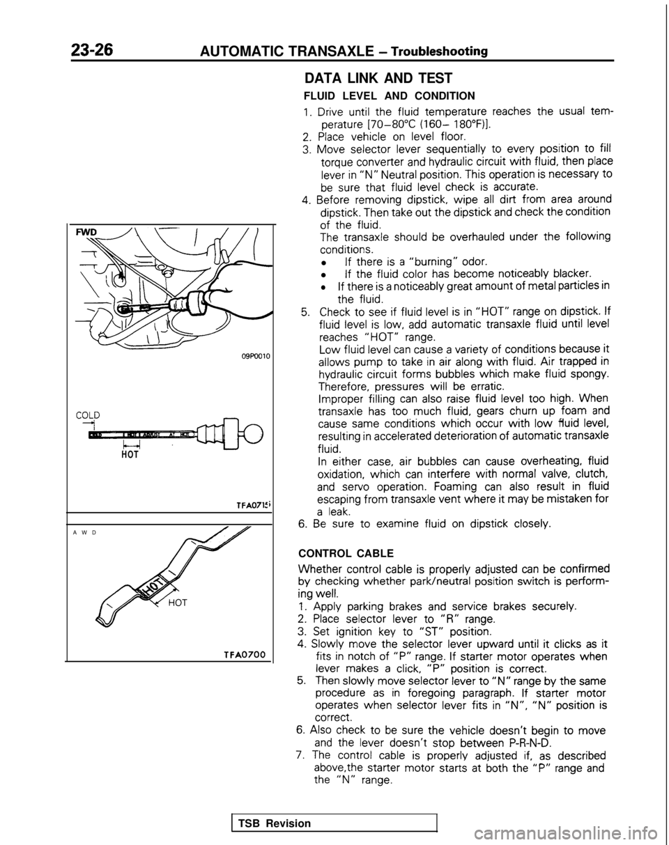
HOT
TFA0715
AW
D
TFA0700
DATA LINK AND TEST
FLUID LEVEL AND CONDITION
1. Drive until the
fluid
temperature
reaches the
usual tem-
perature
[70-80°C (160- 18O”F)l.
2. Place
vehicle
on level floor.
3. Move
selector
lever sequentially
to
every
position
to fill
torque
converter
and hydraulic circuit
with fluid,
then
place
lever in “N” Neutral position.
This operation is necessary
t0
be sure that fluid
level check is accurate.
4. Before
removing
dipstick,
wipe all dirt from area around
dipstick.
Then take out
the
dipstick
and check the
condition
of the
fluid.
The
transaxle
should be overhauled under the following
conditions.
l If there
is a “burning” odor.
l If the
fluid
color
has become
noticeably
blacker.
lIf there
is a noticeably
great
amount
of metal particles in
the
fluid.
5.Check to
see if fluid
level is in “HOT” range on dipstick.
If
fluid
level is low, add automatic
transaxle
fluid
until level
reaches “HOT” range.
Low
fluid
level can cause a variety of
conditions
because it
allows
pump
to
take
in air along with fluid. Air trapped in
hydraulic circuit
forms
bubbles
which
make fluid
spongy.
Therefore,
pressures
will be erratic. Improper filling
can also raise fluid level too
high. When
transaxle
has too
much fluid,
gears churn up foam and
cause same
conditions
which occur with low fluid
level, resulting
in accelerated deterioration
of
automatic
transaxle
fluid.
In
either
case, air bubbles
can cause overheating,
fluid
oxidation,
which can interfere
with normal valve, clutch,
and
servo
operation.
Foaming can also result
in fluid
escaping
from
transaxle
vent where it
may be mistaken
for
a leak.
6. Be
sure to
examine
fluid
on dipstick
closely.
CONTROL CABLE
Whether control
cable is properly
adjusted
can be confirmed
by
checking
whether park/neutral
position
switch is perform-
ing
well.
1.
Apply
parking brakes and service
brakes securely.
2. Place
selector
lever
to
“R” range.
3. Set ignition
key to
“ST” position.
4.
Slowly
move
the
selector
lever
upward
until it
clicks as it
fits in
notch of “P” range. If starter
motor
operates
when
lever makes a click, “P”
position
is correct.
5.Then slowly
move
selector
lever to “N” range by
the
same
procedure as in foregoing
paragraph. If starter
motor
operates
when selector
lever
fits in ‘IN”, “N” position
is correct.
6.
Also check to be sure the
vehicle
doesn’t
begin to move
and
the
lever
doesn’t
stop
between
P-R-N-D.
7. The control
cable is properly
adjusted if, as described
above,the
starter
motor
starts
at both the
“P” range and the
“N” range.
TSB Revision