fuel MITSUBISHI GALANT 1989 Service Repair Manual
[x] Cancel search | Manufacturer: MITSUBISHI, Model Year: 1989, Model line: GALANT, Model: MITSUBISHI GALANT 1989Pages: 1273, PDF Size: 37.62 MB
Page 1 of 1273
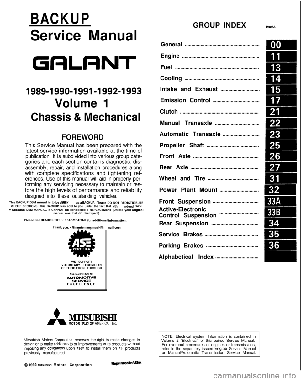
BACKUP
Service Manual
GRLRNT
1989-1990-1991-1992-1993
Volume 1
Chassis & Mechanical
FOREWORD
This Service Manual has been prepared with thelatest service information available at the time of
publication. It is subdivided into various group cate-
gories and each section contains diagnostic, dis-
assembly, repair, and installation procedures along
with complete specifications and tightening ref-
erences. Use of this manual will aid in properly per-
forming any servicing necessary to maintain or res-
tore the high levels of performance and reliability
designed into these outstanding vehicles.
This BACKUP DSM manual is to be used DNLY as
a SACKUP. please DIJ NOT REDISTRIBUTEWHOLE SECTIONS. This BACKUP was sold to you under the fact that you do indeed
DWNa GENUINE DSM MANUAL. It CANNOT BE considered a REPLACEMENT (Unless your
original
manual was lost or
destroyed.) Please
See
README.TXT
or
README.HTML
for additional
information.
1kyou.
- Gjmpiemym_ay&?h
@
A
.
.”
WE SUPPORT
VOLUNTARY TECHNICIAN
CERTIFICATION THROUGH
Nallonal lnsrltule forAU~~~v3~;VPCT:VE
EXCELLENCE naiLcorn
MITSUBISHIMOTOR SALES OF AMERICA. Inc.
Mltsublshl Motors Corporat!on reserves the right to make changes indesign or to make additions to or Improvements In Its products
wlthout~mposng any obllgatlons upon Itself to install them on its productspreviously manufactured
0 1992 Mitsubishi Motors CorporationRcprintedinUSA
GROUP INDEXMOOAA-
General.........................................................
Engine...........................................................
Fuel................................................................
Cooling.........................................................
Intake and Exhaust..............................
Emission Control....................................
Clutch............................................................
Manual Transaxle..................................
Automatic Transaxle............................
Propeller Shaft........................................
Front Axle..................................................
Rear Axle....................................................
Wheel and Tire.......................................
Power Plant Mount..............................
Front Suspension...................................
Active-Electronic
Control Suspension..............................m
A
Rear Suspension....................................&
Service Brakes.........................................
Parking Brakes........................................
Alphabetical Index.................................
NOTE: Electrical system Information is contained in
Volume 2 “Electrical” of this paired Service Manual.
For overhaul procedures of engines or transmissions,
refer to the separately issued Engine
Service Manual
or Manual/Automatic Transmission Service Manual.
Page 3 of 1273
00-l
GENERAL
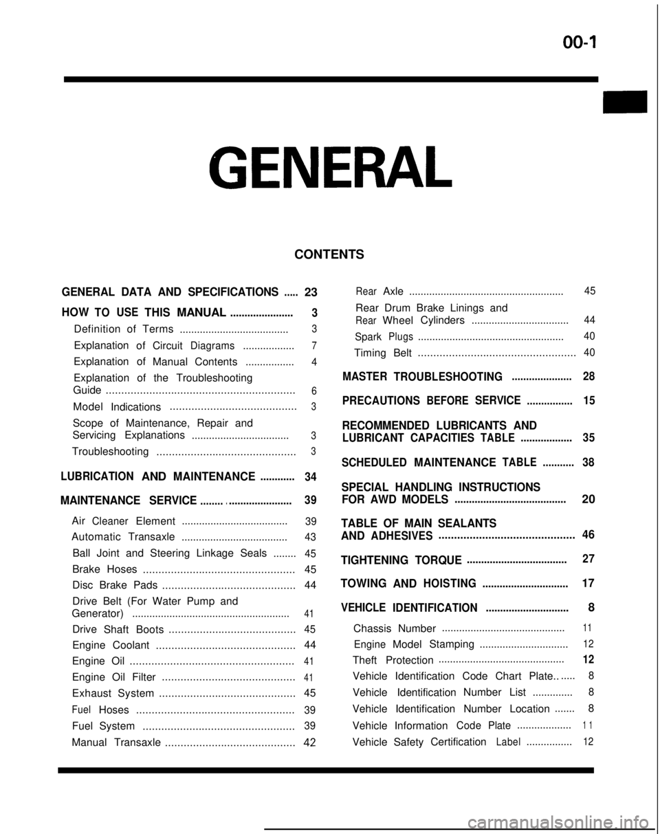
CONTENTS
GENERAL DATA AND SPECIFICATIONS.....23
HOWTOUSETHISMANUAL......................
3
Definition of Terms ......................................3
ExplanationofCircuitDiagrams..................7
Explanation of
ManualContents .................4
Explanation of the Troubleshooting
Guide .............................................................
6
Model
Indications .........................................3
Scope of Maintenance, Repair and
Servicing Explanations
..................................
3
Troubleshooting .............................................3
LUBRICATIONANDMAINTENANCE............
34
MAINTENANCE SERVICE............................... 39
AirCleanerElement
.....................................39
Automatic
Transaxle
.....................................43
Ball Joint and Steering Linkage Seals ........45
Brake Hoses................................................. 45
Disc Brake Pads ........................................... 44
Drive Belt (For Water Pump and
Generator) .......................................................
41
Drive
Shaft Boots .........................................45
Engine Coolant
............................................. 44
Engine Oil .....................................................
41
Engine Oil Filter ...........................................41
Exhaust System
............................................ 45
FuelHoses
...................................................39
Fuel System
.................................................39
Manual Transaxle ..........................................42
RearAxle......................................................45
Rear Drum Brake Linings and
RearWheel Cylinders
..................................44
Spark
Plugs...................................................40
Timing Belt...................................................40
MASTER
TROUBLESHOOTING.....................28
PRECAUTIONS
BEFORESERVICE................15
RECOMMENDED LUBRICANTS AND
LUBRICANT CAPACITIESTABLE..................35
SCHEDULED
MAINTENANCETABLE ...........38
SPECIAL HANDLING INSTRUCTIONS
FOR AWD MODELS
.......................................20
TABLE OF MAIN SEALANTS
AND
ADHESIVES ............................................46
TIGHTENING TORQUE
................................... 27
TOWING
ANDHOISTING ..............................17
VEHICLE
IDENTIFICATION .............................8
Chassis Number ...........................................
11
EngineModel
Stamping
...............................12
Theft Protection ............................................12
Vehicle Identification Code Chart Plate.......
8
Vehicle Identification Number List
..............8
Vehicle Identification Number Location .......
8
Vehicle Information
CodePlate...................1 1
Vehicle SafetyCertificationLabel................12
Page 5 of 1273
GENERAL - How to Use This Manual00-3
HOW
TO USE THIS MANUALMOOBMTO
SCOPE OF MAINTENANCE, REPAIR AND
DEFINITION OF TERMS
SERVICING EXPLANATIONS STANDARD VALUE
This manual provides explanations, etc. concerning procedures for the inspection, maintenance, repair
and servicing of the subject model. Unless other-
wise specified, each service procedure covers all models. Procedures covering specific models are
identified by the model codes, or similar designation
(engine type, transaxle type, etc.). A description of
these designations is covered in this unit under “VEHICLE IDENTIFICATION”.
SERVICE ADJUSTMENT PROCEDURES
“Service Adjustment Procedures” are procedures
for performing inspections and adjustments of
particularly important locations with regard to the
construction and for maintenance and servicing, but
other inspections (for looseness, play, cracking,
damage, etc.) must also be performed.
SERVICE PROCEDURES
The service steps are arranged in numerical order and attentions to be paid in performing vehicleservice are described in detail in SERVICE POINTS.
TROUBLESHOOTING
Troubleshootinqs are classified into master trou-
bleshooting and group troubleshooting and located
as follows:
The master troubleshooting is prepared when the trouble symptom relates to two or more groups and
given in MASTER TROUBLESHOOTING.
The group troubleshooting guide is prepared for causes of problems related to that individual group
only; a troubleshooting guide is prepared for each
appropriate group. Indicates the value used as the standard for judging
the quality of a part or assembly on inspectian or the
value to which the part or assembly is corrected and
adjusted. It is given by tolerance.
LIMIT
Shows the standard for judging the quality of a part
or assembly on inspection and means the maximum
or minimum value within which the part or assembly must be kept functionally or in strength. It is a value
established outside the range of standard value.
REFERENCE VALUE
Indicates the adjustment value prior to starting the
work (presented in order to facilitate assembly and adjustment procedures, and so they can be
com- pleted
in a shorter time).
CAUTION
Indicates the presentation of information particularly
vital to the worker during the performance of maintenance and servicing procedures in order to
avoid the possibility of injury to the worker; or
damage to component parts, or a reduction of
component or vehicle function or performance, etc.
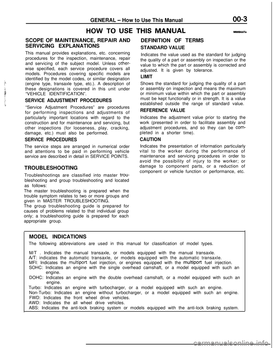
MODEL INDICATIONS
The following abbreviations are used in this manual for classification o\
f model types.
M/T . Indicates the manual transaxle, or models equipped with the manual\
transaxle.
A/T: indicates the automatic transaxle, or models equipped with the automati\
c transaxle.
MFI: Indicates the multiport
fuel injection, or engines equipped with the
multiport fuel injection.
SOHC: Indicates an engine with the single overhead camshaft, or a model \
equipped with such an engine.
DOHC: Indicates an engine with the double overhead camshaft, or a model \
equipped with such an engine.
Turbo: Indicates an engine with turbocharger, or a model equipped with s\
uch an engine. Non-Turbo: Indicates an engine without turbocharger, or a model equipped\
with such an engine.FWD: Indicates the front wheel drive vehicles.
AWD: Indicates the all wheel drive vehicles. ABS: Indicates the anti-lock braking system or models equipped with the \
anti-lock braking system.
Page 20 of 1273
00-l 8GENERAL - Towing and Hoisting
SAFETY PRECAUTIONS
The following precautions should be taken when towing thevehicle.
1.DO NOT LIFT OR TOW THE VEHICLE BY ATTACHING TO
OR WRAPPING AROUND THE BUMPER.
2. Any loose or protruding parts of damaged vehicle such as hoods, doors, fenders, trim, etc., should be secured prior to
moving the vehicle.
3.Operator should refrain from going under a vehicle while it
is lifted by the towing equipment, unless the vehicle in
adequately supported by satefy stands.
4. Never allow passengers to ride in a towed vehicle. 5. State and local rules and regulations must be followed when towing a vehicle.
Refer to the section “Special Handling Instructions for AWD
Models”.
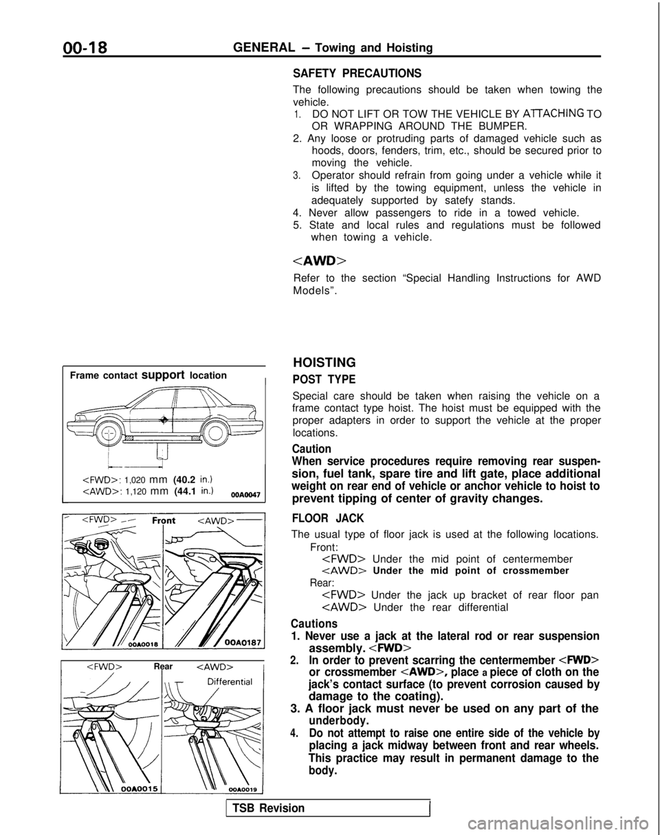
Frame contact support location
I
HOISTING
POST TYPE
Special care should be taken when raising the vehicle on a
frame contact type hoist. The hoist must be equipped with the
proper adapters in order to support the vehicle at the proper
locations.
Caution
When service procedures require removing rear suspen-
sion, fuel tank, spare tire and lift gate, place additional
weight on rear end of vehicle or anchor vehicle to hoist to
prevent tipping of center of gravity changes.
FLOOR JACK
The usual type of floor jack is used at the following locations.
Front:
tAWD> Under the mid point of crossmember
Rear:
Cautions
1. Never use a jack at the lateral rod or rear suspension
assembly.
2.In order to prevent scarring the centermember
or crossmember
place a piece of cloth on the
jack’s contact surface (to prevent corrosion caused by
damage to the coating).
3. A floor jack must never be used on any part of the
underbody.
4.Do not attempt to raise one entire side of the vehicle by
placing a jack midway between front and rear wheels.
This practice may result in permanent damage to the
body.
TSB RevisionI
Page 26 of 1273
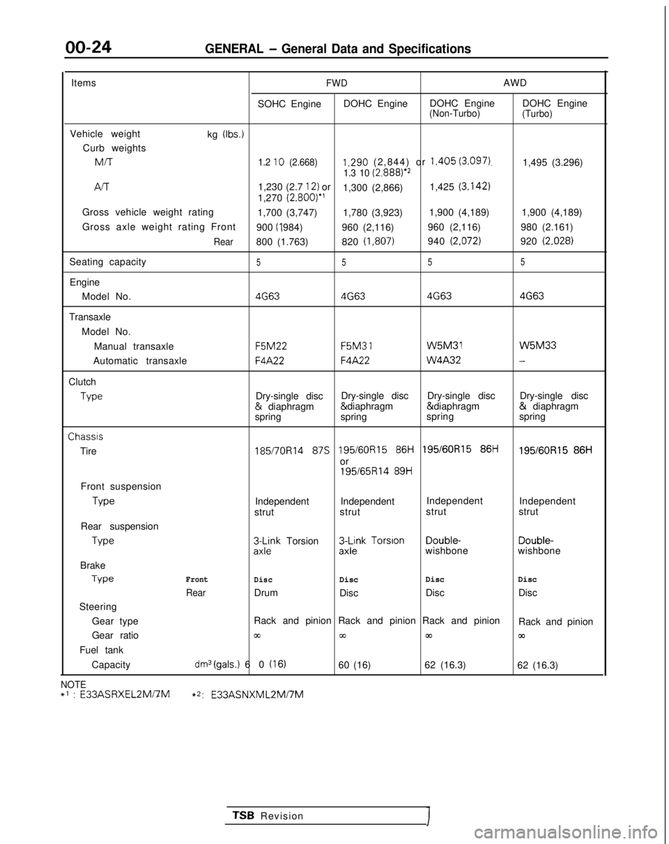
00-24GENERAL - General Data and Specifications
ItemsFWDAWD
SOHC Engine DOHC Engine DOHC Engine DOHC Engine
(Non-Turbo)
(Turbo)
Vehicle weight
kg (Ibs.)
Curb weightsMIT
1.2 10 (2.668)1.290 (2,844) or 1.405 (3.097).1,495 (3.296)1.3 10 (2.8881e2
/-v-r1,230 (2.7 12) or
1,300 (2,866) 1,425 (3.142)
1,270
(2.800)”
Gross vehicle weight rating 1,700 (3,747) 1,780 (3,923)1,900 (4,189)
1,900 (4,189)
Gross axle weight rating Front 900 (I ,984)
960 (2,116) 960 (2,116)
980 (2.161)
Rear800 (1.763)820 (1,807)940 (2.072)920 (2.028)
Seating capacity5 55 5
Engine
Model No.
4G634G63 4G634G63
Transaxle
Model No.Manual transaxle F5M22 F5M3
1 W5M31 W5M33
Automatic transaxle
F4A22F4A22 W4A32-
Clutch
Type
Dry-single disc
Dry-single disc
Dry-single disc Dry-single disc &
diaphragm & diaphragm & diaphragm &
diaphragm
spring spring spring
springChassis
Tire
185/7OR14 87s 195/60R15 86i-i 195/60R15 86ti195/60R15 86H
or
195/65R14 89H
Front suspension Type
Independent Independent
Independent
Independent
strut strut strut
strut
Rear suspension Type
3L$k Torsion3$k Torsion Double-
Double-
wishbone wishbone
Brake Type
Front
DiscDisc Disc
Disc
RearDrum
Disc Disc
Disc
Steering
Gear type Rack and pinion Rack and pinion Rack and pinion
Rack and pinion
Gear ratio
cc00m03
Fuel tank
Capacity
dm3(gals.) 60 (16)60 (16) 62 (16.3)
62 (16.3)
NOTE+’ : E33ASRXEL2Mi7M~2:
E33ASNXML2Mi7M
TSB RevisionI
Page 28 of 1273
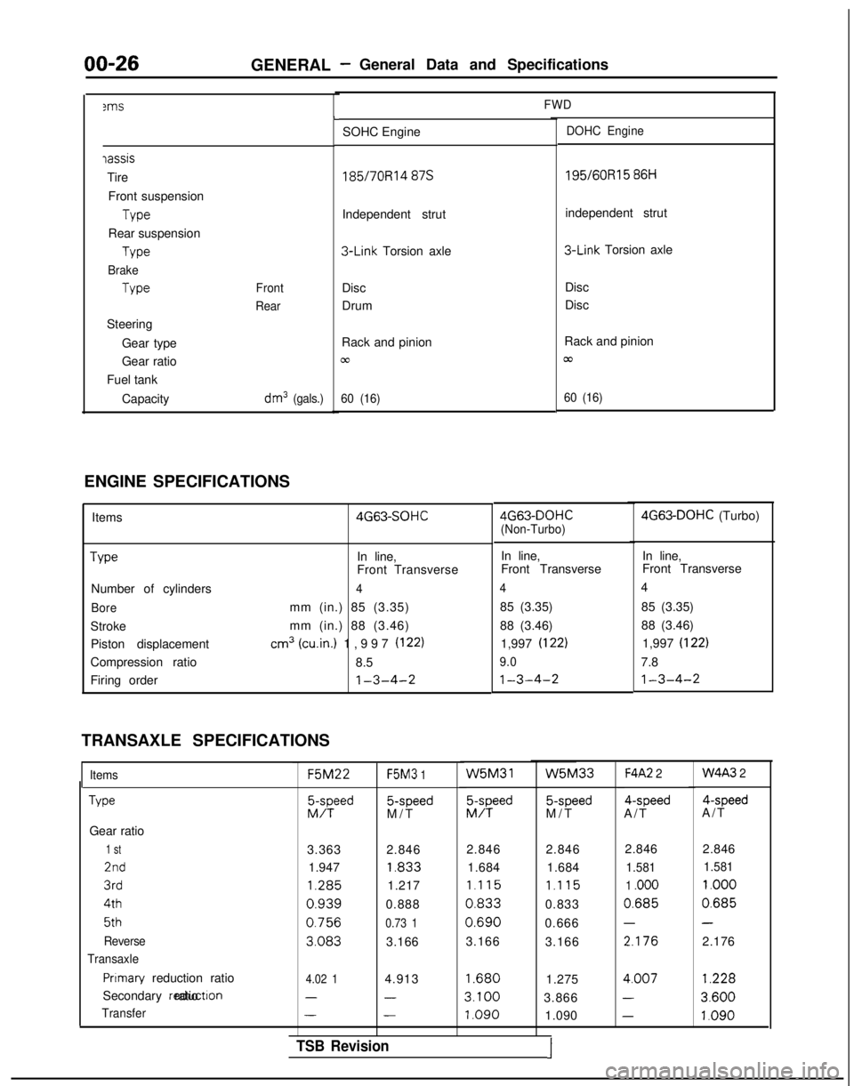
00-263ms
GENERAL -General Data and Specifications
FWD
iassis
Tire
Front suspension Type
Rear suspension Type
Brake
Type
Steering Gear type
Gear ratio
Fuel tank
Capacity
Front
Rear
dm3 (gals.)
L
SOHC EngineDOHC Engine
185/7ORl4 87s 195/60R15
86H
Independent strut independent strut 3-Link
Torsion axle 3-Link
Torsion axle
Disc
Drum Disc
Disc
Rack and pinion
cc
60 (16)
Rack and pinion
/cu
60 (16)
ENGINE SPECIFICATIONS Items Type
Number of cylinders
Bore
StrokePiston displacement
Compression ratio
Firing order 4G63-SOHC
In line,
Front Transverse
4
mm (in.) 85 (3.35)
mm (in.) 88 (3.46)
cm3 (win.) 1,997 (122)
8.5
1-3-4-2
TRANSAXLE SPECIFICATIONS
Items
Type
Gear ratio
1 st
2nd
3rd 4th
5th
Reverse
Transaxle
Pnmary reduction ratio
Secondary reductron ratio
Transfer F5M22
F5M3
1 5-speed
M/T W5M31
EFd
5-speed
M/T
F4A2 2 4-speed
A/T 4-speed
A/T
3.363 2.846 2.846 2.846
1.947 1.833
1.684 1.684 1.285
1.217
1.115 1.115
0.9390.8880.8330.833
0.7560.73 10.6900.666
3.0833.166
3.166
3.166 2.846 2.846
1.581
1.581
1 .ooo 1.000
0.6850.685
--
2.1762.176
4.02 14.9131.6801.2754.007
1.228
---3.1003.8663.600
---1.0901.090
1.0904G63-DOHC
(Non-Turbo) 4G63-DOHC
(Turbo)
In line, In line,
Front Transverse Front Transverse
44
85 (3.35) 85 (3.35)
88 (3.46) 88 (3.46)
1,997 (I
22)1,997 (I 22)
9.0
7.8
1-3-4-21-3-4-2
W5M33W4A3 2
TSB Revision1
Page 30 of 1273
00-28GENERAL - Tightening Torque/Master Troubleshooting
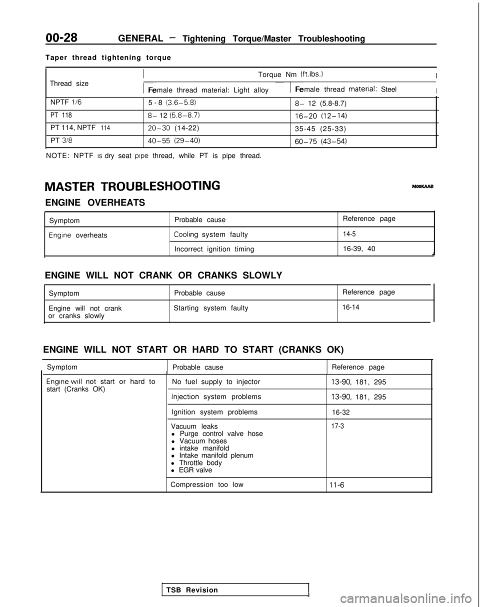
Taper thread tightening torque
Thread size
ITorque Nm (ftlbs.)I
r~Female thread material: Light alloy1-Female thread material: SteelI
NPTF II65-8 (3.6-5.8)
PT 1188- 12 (5.8-8.7)
PT 114, NPTF11420-30 (14-22)
PT
31840-55 (29-40)
NOTE: NPTF IS dry seat pope thread, while PT is pipe thread.
8- 12 (5.8-8.7)
16-20 (12-14)
35-45 (25-33)
60-75 (43-54)
MASTER TROUBLESHOOTING hlooKAAB
ENGINE OVERHEATS Symptom
Engine overheats Probable cause
Reference pageCoolrng system faulty14-5
Incorrect ignition timing
16-39, 40
ENGINE WILL NOT CRANK OR CRANKS SLOWLY Symptom Probable cause
Engine will not crank Starting system faulty
or cranks slowly Reference page
16-14
ENGINE WILL NOT START OR HARD TO START (CRANKS OK)
Symptom Probable cause Reference page
Engrne WIII not start or hard to
start (Cranks OK) No fuel supply to injector Injection
system problems
Ignition system problems
Vacuum leaks l Purge control valve hose
l Vacuum hoses
l intake manifold
l Intake manifold plenum
l Throttle body
l EGR valve13-90, 181, 295
13-90, 181, 295
16-32
17-3
Compression too low11-6
TSB Revision
Page 31 of 1273
GENERAL - Master Troubleshooting00-29
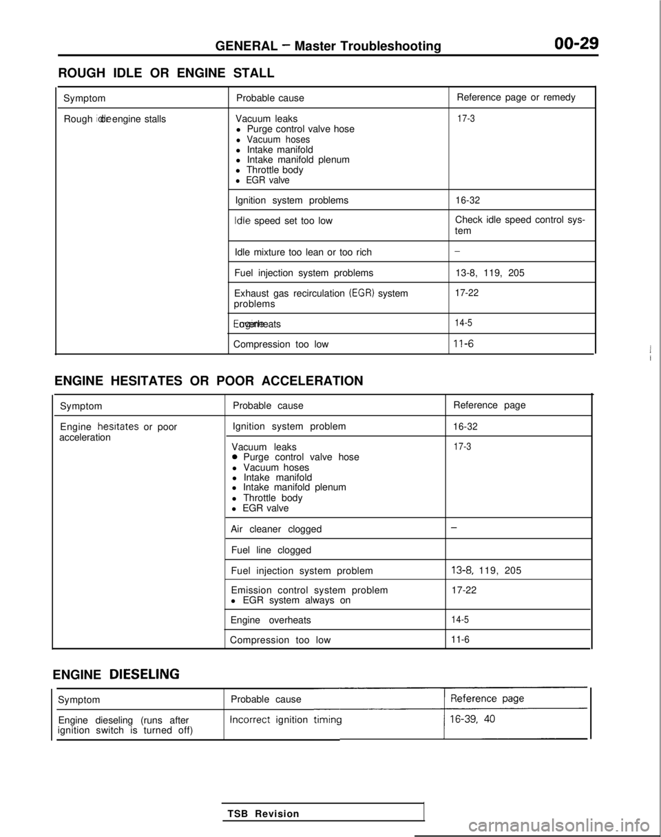
ROUGH IDLE OR ENGINE STALL
SymptomRough idle or engine stalls
Probable cause
Vacuum leaks l Purge control valve hose
l Vacuum hosesl Intake manifold
l Intake manifold plenum
l Throttle body
l EGR valve
Ignition system problems Idle
speed set too low Reference page or remedy
17-3
16-32
Check idle speed control sys-
tem
Idle mixture too lean or too rich
Fuel injection system problems
Exhaust gas recirculation
(EGR) system
problems Engine overheats
Compression too low
-
13-8, 119, 205
17-22
14-5
11-6
ENGINE HESITATES OR POOR ACCELERATION
Symptom
Engine hesrtates
or poor
acceleration Probable cause
Ignition system problem
Vacuum leaks
0 Purge control valve hose
l Vacuum hoses
l Intake manifold
l Intake manifold plenum
l Throttle body
l EGR valve Reference page
16-32
17-3
Air cleaner clogged
Fuel line clogged
Fuel injection system problem
Emission control system problem
l EGR system always on
Engine overheats
Compression too low-
13-8, 119, 205
17-22
14-5
11-6
ENGINE DIESELING
Probable cause Incorrect
ignition
timincc
TSB Revision
Symptom
Engine dieseling (runs after
ignition switch is turned off)
Page 32 of 1273
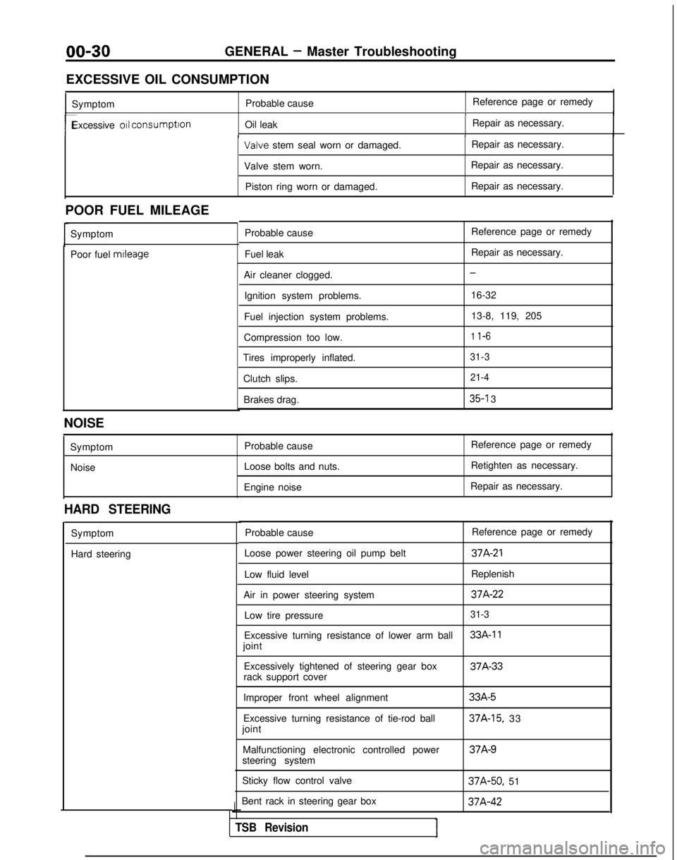
00-30GENERAL - Master Troubleshooting
EXCESSIVE OIL CONSUMPTION Symptom Probable cause Reference page or remedy
1
r-Excessive 011 consumption
Oil leak Repair as necessary.I Valve
stem seal worn or damaged. Repair as necessary.
Valve stem worn. Repair as necessary.
Piston ring worn or damaged. Repair as necessary.
POOR FUEL MILEAGE Symptom
Poor fuel mtleage
Probable cause
Fuel leak
Air cleaner clogged. Ignition system problems.
Fuel injection system problems.
Compression too low.
Tires improperly inflated.
Clutch slips.Brakes drag. Reference page or remedy
Repair as necessary.
-
16-32
13-8, 119, 205
1 l-6
31-3 21-4
35-l 3
NOISE
SymptomNoise Probable cause
Loose bolts and nuts.
Engine noise Reference page or remedy
Retighten as necessary.
Repair as necessary.
HARD STEERING
Symptom
Hard steering Probable cause
Reference page or remedy
Loose power steering oil pump belt
37A-21
Low fluid level Replenish
Air in power steering system
37A-22
Low tire pressure31-3
Excessive turning resistance of lower arm ball33A-11
joint Excessively tightened of steering gear box 37A-33
rack support cover
Improper front wheel alignment
Excessive turning resistance of tie-rod ball
joint
Malfunctioning electronic controlled power
steering system
Sticky flow control valve
Bent rack in steering gear box
J
TSB RevisionI
33A-5
37A-15, 33 37A-9
37A-50,
51 37A-42
Page 36 of 1273
00-34GENERAL- Lubrication and Maintenance
LUBRICATION AND
MAINTE-
NANCEMOOPA-
Maintenance and lubrication service recommenda-
tions have been compiled to provide maximum protection for the vehicle owner’s investment
against all reasonable types of driving conditions. Since these conditions vary with the individual
vehicle owner’s driving habits, the area in which the
vehicle is operated and the type of driving to which
the vehicle is subjected, it is necessary to prescribe lubrication and maintenance service on a time
frequency as well as mileage interval basis.
Oils, lubricants and greases are classified and
graded according to standards recommended by the Society of Automotive Engineers (SAE), the Amer-
ican Petroleum Institute (API) and the National
Lubricating Grease Institute (NLGI).
MAINTENANCE SCHEDULES Information for service maintenance is provided
under “SCHEDULED MAINTENANCE TABLE”.
Three schedules are provided; one for “Required Maintenance”, one for “General Maintenance” and
one for “Severe Usage Service”.
The item numbers used in the “SCHEDULED MAINTENANCE TABLE” correspond to th
e
“MAINTENANCE SERVICE” section numbers.
SEVERE SERVICE
Vehicles operating under severe service conditions
will require more frequent service. Component service information
isIncluded i
n
appropriate units for vehicles operating under one or
more of the following conditrons:
1.Trailer towing or police, taxi, or
commerciai
type
operation
2. Operation of Vehicle (1) Short-trip operation at freezing temperature(engine not thoroughly warmed up)
(2) More than 50% operation in heavy city traffic during hot weather above
32°C (90°F)
(3) Extensive idling
(4) Driving in sandy areas
(5) Driving in salty areas
(6) Driving in dusty conditions
ENGINE OIL
The SAE grade number indicates the viscosity of engine oils, for example, SAE 30, which is a single
grade oil. Engine oils are also identified by a dual number, for example, SAE 1
OW-30, which Indicates
a multigrade oil.
The API classification system defines oil perform- ance in terms of engine usage. Only engine oil
designed “For Service SG” or “For Service
SGKD”,
when available, should be used. These oils contain
sufficient chemical additives to provide maximum
engine protection. Both the SAE grade and the API
designation can be found on the container.
Caution
Test results submitted to EPA have shown that
laboratory animals develop skin cancer after
prolonged contact with used engine oil. Accor-
dingly, the potential exists for humans to de-
velop a number of skin disorders, including
cancer, from such exposure to used engine oil.
Care should be taken, therefore, when changing engine oil, to minimize the amount and length of
exposure time to used engine oil on your skin.
Protective clothing and gloves, that cannot be
penetrated by oil, should be worn. The skin
should be thoroughly washed with soap and
water, or use waterless hand cleaner, to remove
any used engine oil. Do not use gasoline,
thinners, or solvents.
GEAR LUBRICANTS
The SAE grade number also indicates the viscosity of Multi-Purpose Gear Lubricants.
The API classfication
system defines gear lubricants
in terms of usage. Typically gear lubricants conform-
ing to API
GL-4 or GL-5 with a viscosity of SAE 75W-85W
are recommended for manual transaxle.
LUBRICANTS
- GREASES
Semi-solid lubricants, bear the
NLGI designation and
are further classified as grades 0, 1, 2, 3 etc.
Whenever “Chassis Lubricant” is specified,
Multi-
Purpose Grease, NLGI grade 2 should be used.
FUEL USAGE STATEMENT
Your vehicle must use unleaded gasoline only.
This vehicle has a fuel filler tube especially designed
to accept only the smaller-diameter unleaded gaso- line
dispensrng nozzle.
Caution
Using leaded gasoline in your vehicle will damage
the catalytic converter, and affect the warranty
coverage validity.
All vehicles except those with DOHC engines
Your vehicle is designed to operate on unleaded
gasoline having a minimum octane rating of 87 or
91 RON (Research Octane Number).
Vehicles equipped with DOHC engines
Your vehicle is designed to operate on premiumunleaded gasoline having a minimum
octane rating
of 91 or 95 RON (Research Octane Number).
TSB Revision