gas type MITSUBISHI GALANT 1989 Service Repair Manual
[x] Cancel search | Manufacturer: MITSUBISHI, Model Year: 1989, Model line: GALANT, Model: MITSUBISHI GALANT 1989Pages: 1273, PDF Size: 37.62 MB
Page 36 of 1273
00-34GENERAL- Lubrication and Maintenance
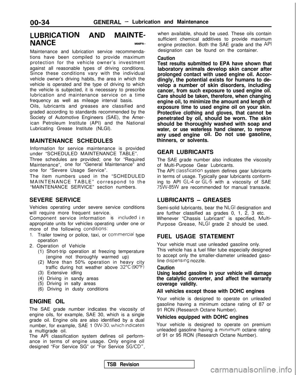
LUBRICATION AND
MAINTE-
NANCEMOOPA-
Maintenance and lubrication service recommenda-
tions have been compiled to provide maximum protection for the vehicle owner’s investment
against all reasonable types of driving conditions. Since these conditions vary with the individual
vehicle owner’s driving habits, the area in which the
vehicle is operated and the type of driving to which
the vehicle is subjected, it is necessary to prescribe lubrication and maintenance service on a time
frequency as well as mileage interval basis.
Oils, lubricants and greases are classified and
graded according to standards recommended by the Society of Automotive Engineers (SAE), the Amer-
ican Petroleum Institute (API) and the National
Lubricating Grease Institute (NLGI).
MAINTENANCE SCHEDULES Information for service maintenance is provided
under “SCHEDULED MAINTENANCE TABLE”.
Three schedules are provided; one for “Required Maintenance”, one for “General Maintenance” and
one for “Severe Usage Service”.
The item numbers used in the “SCHEDULED MAINTENANCE TABLE” correspond to th
e
“MAINTENANCE SERVICE” section numbers.
SEVERE SERVICE
Vehicles operating under severe service conditions
will require more frequent service. Component service information
isIncluded i
n
appropriate units for vehicles operating under one or
more of the following conditrons:
1.Trailer towing or police, taxi, or
commerciai
type
operation
2. Operation of Vehicle (1) Short-trip operation at freezing temperature(engine not thoroughly warmed up)
(2) More than 50% operation in heavy city traffic during hot weather above
32°C (90°F)
(3) Extensive idling
(4) Driving in sandy areas
(5) Driving in salty areas
(6) Driving in dusty conditions
ENGINE OIL
The SAE grade number indicates the viscosity of engine oils, for example, SAE 30, which is a single
grade oil. Engine oils are also identified by a dual number, for example, SAE 1
OW-30, which Indicates
a multigrade oil.
The API classification system defines oil perform- ance in terms of engine usage. Only engine oil
designed “For Service SG” or “For Service
SGKD”,
when available, should be used. These oils contain
sufficient chemical additives to provide maximum
engine protection. Both the SAE grade and the API
designation can be found on the container.
Caution
Test results submitted to EPA have shown that
laboratory animals develop skin cancer after
prolonged contact with used engine oil. Accor-
dingly, the potential exists for humans to de-
velop a number of skin disorders, including
cancer, from such exposure to used engine oil.
Care should be taken, therefore, when changing engine oil, to minimize the amount and length of
exposure time to used engine oil on your skin.
Protective clothing and gloves, that cannot be
penetrated by oil, should be worn. The skin
should be thoroughly washed with soap and
water, or use waterless hand cleaner, to remove
any used engine oil. Do not use gasoline,
thinners, or solvents.
GEAR LUBRICANTS
The SAE grade number also indicates the viscosity of Multi-Purpose Gear Lubricants.
The API classfication
system defines gear lubricants
in terms of usage. Typically gear lubricants conform-
ing to API
GL-4 or GL-5 with a viscosity of SAE 75W-85W
are recommended for manual transaxle.
LUBRICANTS
- GREASES
Semi-solid lubricants, bear the
NLGI designation and
are further classified as grades 0, 1, 2, 3 etc.
Whenever “Chassis Lubricant” is specified,
Multi-
Purpose Grease, NLGI grade 2 should be used.
FUEL USAGE STATEMENT
Your vehicle must use unleaded gasoline only.
This vehicle has a fuel filler tube especially designed
to accept only the smaller-diameter unleaded gaso- line
dispensrng nozzle.
Caution
Using leaded gasoline in your vehicle will damage
the catalytic converter, and affect the warranty
coverage validity.
All vehicles except those with DOHC engines
Your vehicle is designed to operate on unleaded
gasoline having a minimum octane rating of 87 or
91 RON (Research Octane Number).
Vehicles equipped with DOHC engines
Your vehicle is designed to operate on premiumunleaded gasoline having a minimum
octane rating
of 91 or 95 RON (Research Octane Number).
TSB Revision
Page 37 of 1273
GENERAL -Lubrication and Maintenance/Recommended Lubricants and Lubricant Capacities Table00-35
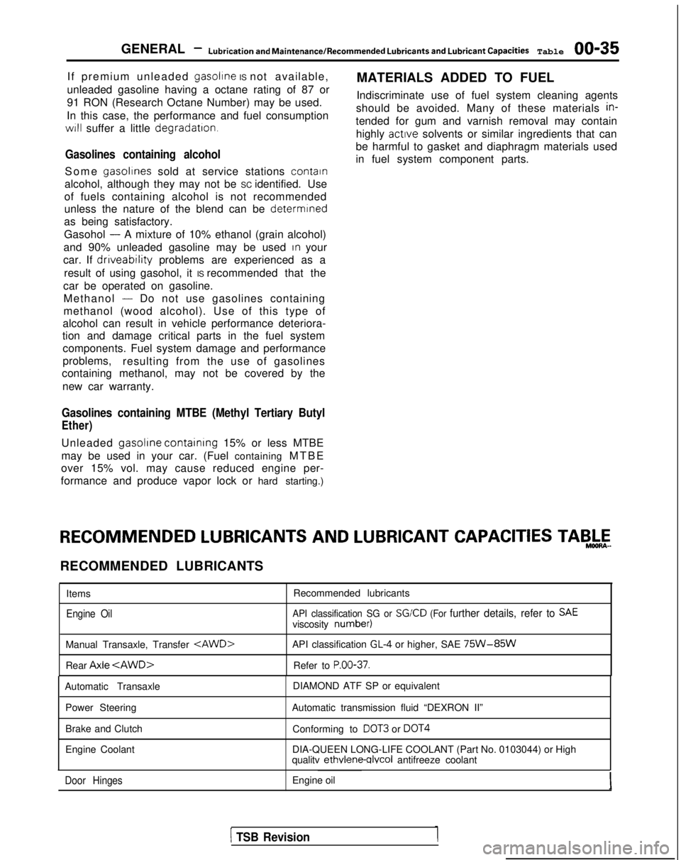
If premium unleaded gasoltne IS not available,
MATERIALS ADDED TO FUEL
unleaded gasoline having a octane rating of 87 or
91 RON (Research Octane Number) may be used. Indiscriminate use of fuel system cleaning agents
In this case, the performance and fuel consumption should be avoided. Many of these materials
in-
WIII suffer a little degradatron.tended for gum and varnish removal may contain
highly active
solvents or similar ingredients that can
be harmful to gasket and diaphragm materials used
in fuel system component parts.
Gasolines containing alcohol
Some gasolrnes sold at service stations contain
alcohol, although they may not be SC identified. Use
of fuels containing alcohol is not recommended
unless the nature of the blend can be
determrned
as being satisfactory.
Gasohol
- A mixture of 10% ethanol (grain alcohol)
and 90% unleaded gasoline may be used
In your
car. If
driveability problems are experienced as a
result of using gasohol, it IS recommended that the
car be operated on gasoline. Methanol
- Do not use gasolines containing
methanol (wood alcohol). Use of this type of
alcohol can result in vehicle performance deteriora-
tion and damage critical parts in the fuel system
components. Fuel system damage and performance
problems, resulting from the use of gasolines
containing methanol, may not be covered by the
new car warranty.
Gasolines containing MTBE (Methyl Tertiary Butyl
Ether)
Unleaded gasolrne containrng
15% or less MTBE
may be used in your car. (Fuel containing MTBE
over 15% vol. may cause reduced engine per-
formance and produce vapor lock or hard starting.) RECOMMENDED
LUBRICANTS AND
LUBRICANT CAPACITIES TAB,&-
RECOMMENDED LUBRICANTS
Items
Engine Oil
Recommended lubricants
API classification SG or SGKD (For further details, refer to SAEviscosity number)
Manual Transaxle, Transfer
Rear Axle
API classification GL-4 or higher, SAE 75W-85W
Refer to P.OO-37.
Automatic Transaxle
Power Steering
Brake and Clutch
Engine Coolant DIAMOND ATF SP or equivalent
Automatic transmission fluid “DEXRON II” Conforming to
DOT3 or DOT4
DIA-QUEEN LONG-LIFE COOLANT (Part No. 0103044) or High
qualitv ethvlene-qlvcol
antifreeze coolant
Door HingesEngine oil
1 TSB Revision
Page 207 of 1273
FUEL SYSTEM
(1) Improper adjustment of the basic idling speed.
(2) Deposits adhering to the ttirottle valve.
(3) Air being taken into the intake manifold due to a gasket leak, etc.
OPERATION
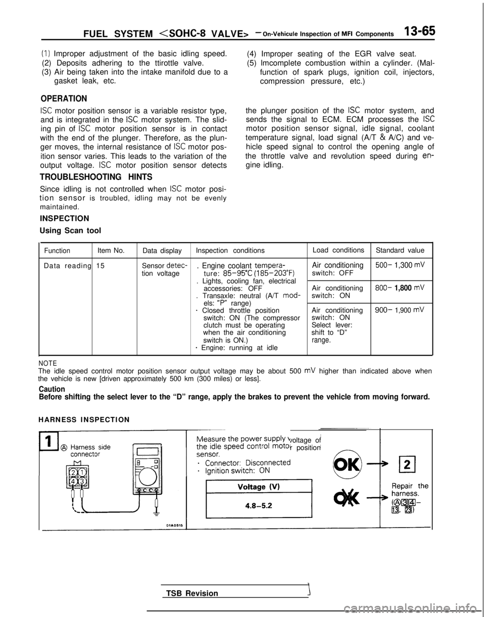
ISC motor position sensor is a variable resistor type,
and is integrated in the
ISC motor system. The slid-
ing pin of
ISC motor position sensor is in contact
with the end of the plunger. Therefore, as the plun- ger moves, the internal resistance of
ISC motor pos-
ition sensor varies. This leads to the variation of the (4) Improper seating of the EGR valve seat.
(5) lmcomplete combustion within a cylinder. (Mal-
function of spark plugs, ignition coil, injectors,
compression pressure, etc.)
the plunger position of the
ISC motor system, and
sends the signal to ECM. ECM processes the
ISC
motor position sensor signal, idle signal, coolant
temperature signal, load signal (A/T &
A/C) and ve-
hicle speed signal to control the opening angle of
the throttle valve and revolution speed during
en-
output voltage. ISC motor position sensor detects gine idling.
TROUBLESHOOTING HINTS
Since idling is not controlled when ISC motor posi-
tion sensor is troubled, idling may not be evenly
maintained.
INSPECTION
Using Scan tool
FunctionItem No. Data display Inspection conditions Load conditions
Standard value
Data reading 15 Sensor detec-
. Engine coolant tempera-
Air conditioning 500- 1,300 mV
tion voltage
ture: 85-95’C (185-203°F)
switch: OFF
. Lights, cooling fan, electrical accessories: OFF Air conditioning 800-
1,800 mV. Transaxle: neutral (A/T
mod-
switch: ON
els: “P”
range)
1 Closed throttle position Air conditioning900- 1,900 mVswitch: ON (The compressorswitch: ON
clutch must be operating Select lever:
when the air conditioning shift to “D”
switch is ON.)
range.* Engine: running at idle
NOTEThe idle speed control motor position sensor output voltage may be about\
500 mV higher than indicated above when
the vehicle is new [driven approximately 500 km (300 miles) or less].
CautionBefore shifting the select lever to the “D” range, apply the brake\
s to prevent the vehicle from moving forward.
HARNESS INSPECTION
Measure the power supply voltage of
the idle speed control motor position
ei;;;it;;sco$ected
__...._ -.-
TSB Revision
Page 227 of 1273
FUEL SYSTEnrll (SOHC-8 VALVE> -On-Vehicule
Inspection of MFI Components13-85
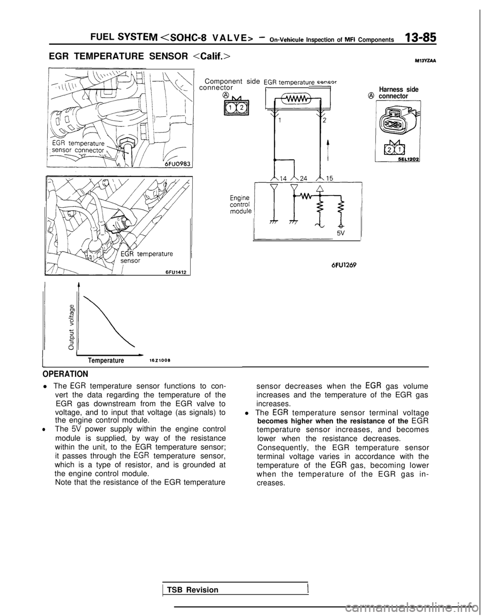
EGR TEMPERATURE SENSOR
\+\+I connectorComponent side EGR temperaturn r-n~nrrHarness side@
connector 6FlJ1412
1
IwTemperaturelEzlooB
OPERATION
l The EGR temperature sensor functions to con-
vert the data regarding the temperature of the EGR gas downstream from the EGR valve to
voltage, and to input that voltage (as signals) to
the engine control module.
lThe 5V power supply within the engine control
module is supplied, by way of the resistance
within the unit, to the EGR temperature sensor; it passes through the
EGR temperature sensor,
which is a type of resistor, and is grounded at
the engine control module. Note that the resistance of the EGR temperature
6FU1269
sensor decreases when the EGR gas volume
increases and the temperature of the EGR gas
increases.
l The EGR temperature sensor terminal voltage
becomes higher when the resistance of the EGR
temperature sensor increases, and becomes
lower when the resistance decreases.
Consequently, the EGR temperature sensor
terminal voltage varies in accordance with the
temperature of the
EGR gas, becoming lower
when the temperature of the EGR gas in-
creases.
TSB RevisionI
Page 431 of 1273
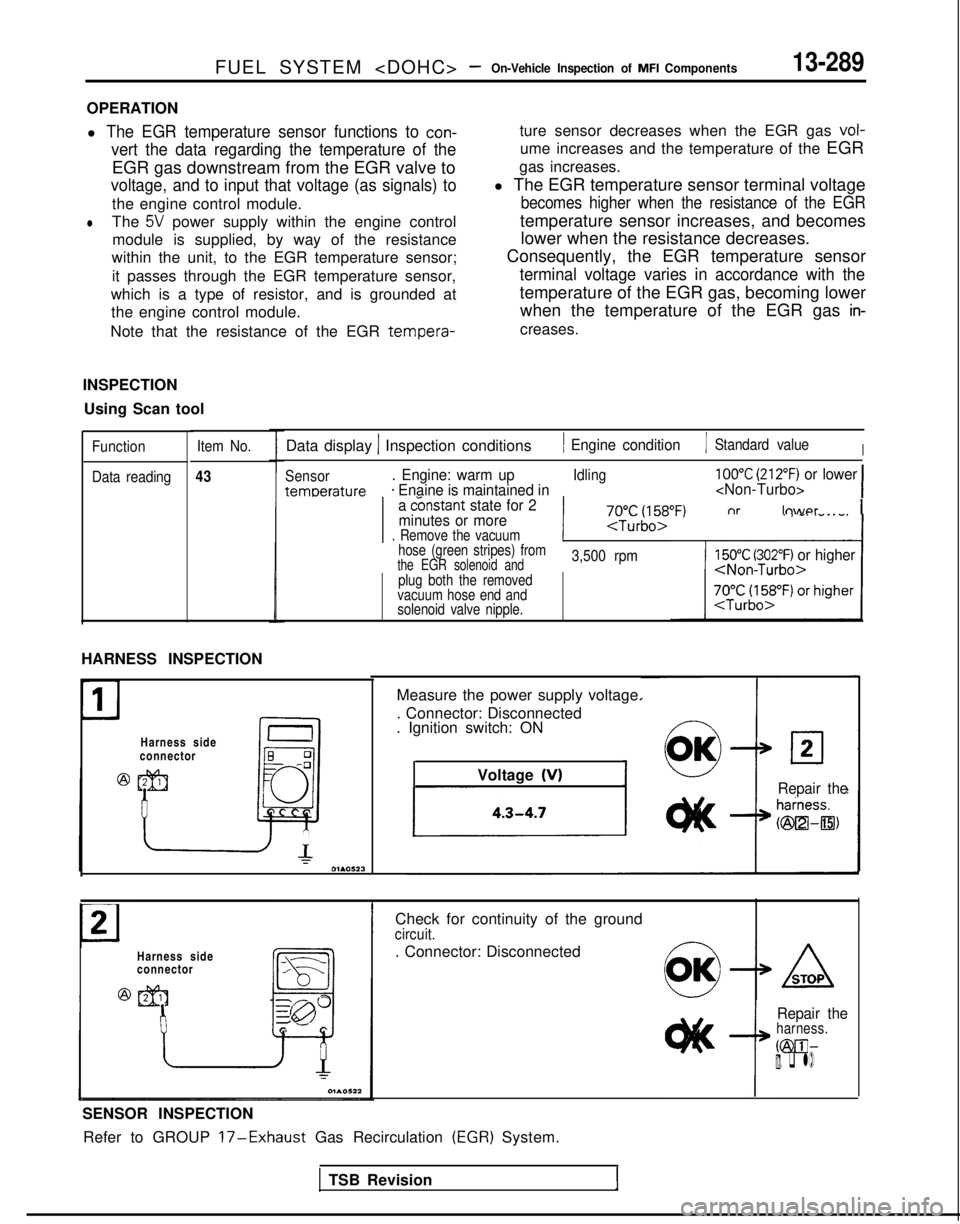
FUEL SYSTEM
OPERATION
l The EGR temperature sensor functions to con-
vert the data regarding the temperature of the
EGR gas downstream from the EGR valve to
voltage, and to input that voltage (as signals) to
the engine control module.
lThe 5V power supply within the engine control
module is supplied, by way of the resistance
within the unit, to the EGR temperature sensor;
it passes through the EGR temperature sensor,
which is a type of resistor, and is grounded at the engine control module.
Note that the resistance of the EGR tempera-
ture sensor decreases when the EGR gas vol-
ume increases and the temperature of the EGR
gas increases.
l The EGR temperature sensor terminal voltage
becomes higher when the resistance of the EGR
temperature sensor increases, and becomes lower when the resistance decreases.
Consequently, the EGR temperature sensor
terminal voltage varies in accordance with the
temperature of the EGR gas, becoming lower when the temperature of the EGR gas
in-
creases.
INSPECTION Using Scan tool
Function Item No.
Data reading
43
Data display 1 Inspection conditions1 Engine condition1 Standard valueI
Sensor. Engine: warm upIdling100°C (212°F) or lower
temoerature* Enaine is maintained in
minutes or more
. Remove the vacuum
11 7J$lfifiF~ nr lower 1
hose (green stripes) fromthe EGR solenoid and3,500 rpm150°C (302°F) or higher/hlnn-Turbo>plug both the removed
vacuum hose end and
solenoid valve nipple.
HARNESS INSPECTION
Harness side
connector Measure the power supply voltage.
. Connector: Disconnected
. Ignition switch: ON
Voltage
(V)Repair the
Harness side
connector Check for continuity of the ground
circuit.
. Connector: Disconnected
SENSOR INSPECTION Refer to GROUP
l7-Exhaust Gas Recirculation (EGR) System.
Repair theharness.
@El-IIll. q l)
TSB Revision
Page 452 of 1273
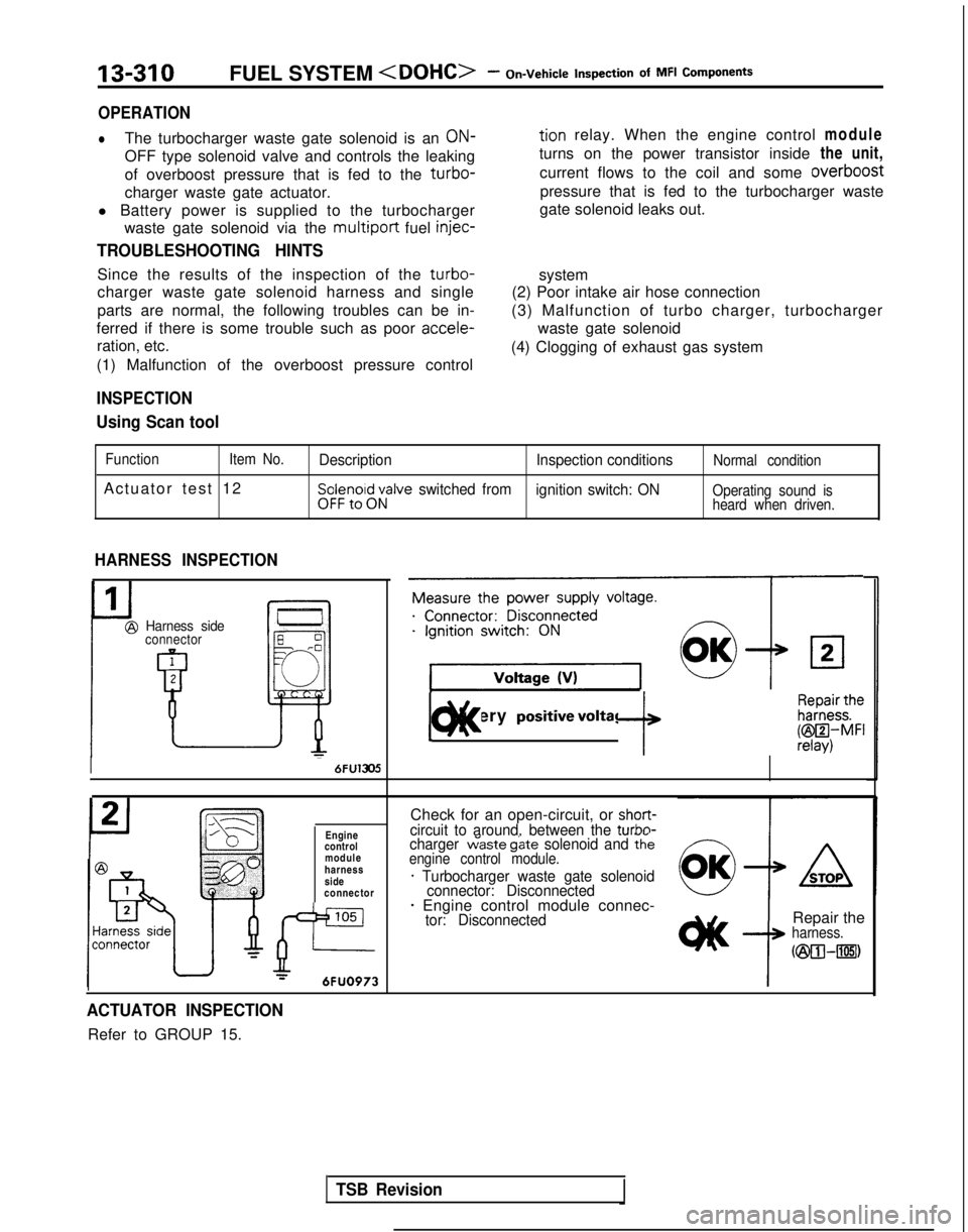
13-310FUEL SYSTEM
of MFI Components
OPERATION
lThe turbocharger waste gate solenoid is an ON-tion relay. When the engine control
module
OFF type solenoid valve and controls the leaking turns on the power transistor inside
the unit,
of overboost pressure that is fed to the
turbo-current flows to the coil and some overboost
charger waste gate actuator. pressure that is fed to the turbocharger waste
l Battery power is supplied to the turbocharger gate solenoid leaks out.
waste gate solenoid via the
multiport fuel injec-
TROUBLESHOOTING HINTS
Since the results of the inspection of the turbo-
charger waste gate solenoid harness and single
parts are normal, the following troubles can be in-
ferred if there is some trouble such as poor accele-
ration, etc.
(1) Malfunction of the overboost pressure control system
(2) Poor intake air hose connection
(3) Malfunction of turbo charger, turbocharger waste gate solenoid
(4) Clogging of exhaust gas system
INSPECTION
Using Scan tool
Function Item No.
Actuator test 12
Description Inspection conditionsNormal condition
Sp:$r?,oi$;;alve switched from
ignition switch: ONOperating sound is
heard when driven.
HARNESS INSPECTION
Harness sideconnector
1
@
uI 6FU1305
Engine
control
module
harness
side
connector
105
JP--r6FUO973
Measure the power supply voltage.
9
1 Battery positivevoltage ]c)ll< f k&f$i
Check for an open-circuit, or short-circuit to around, between the turbn-charger w’aste g&e solenoid and thkengine control module.
* Turbocharger waste gate solenoid
connector: Disconnected
* Engine control module connec-tor: DisconnectedRepair theharness.
C@O--rn)
ACTUATOR INSPECTION
Refer to GROUP 15.
TSB Revision
Page 584 of 1273
14-32COOLING -Engine Coolant Temperature Gauge Unit, Engine Coolant
Temperature Sensor and Engine Coolant Temperature Switch
/
Sensor
J
046003
3
04GOO32
9FUO156
---
--I ‘Oi
l
QQQQQQ2cmn99
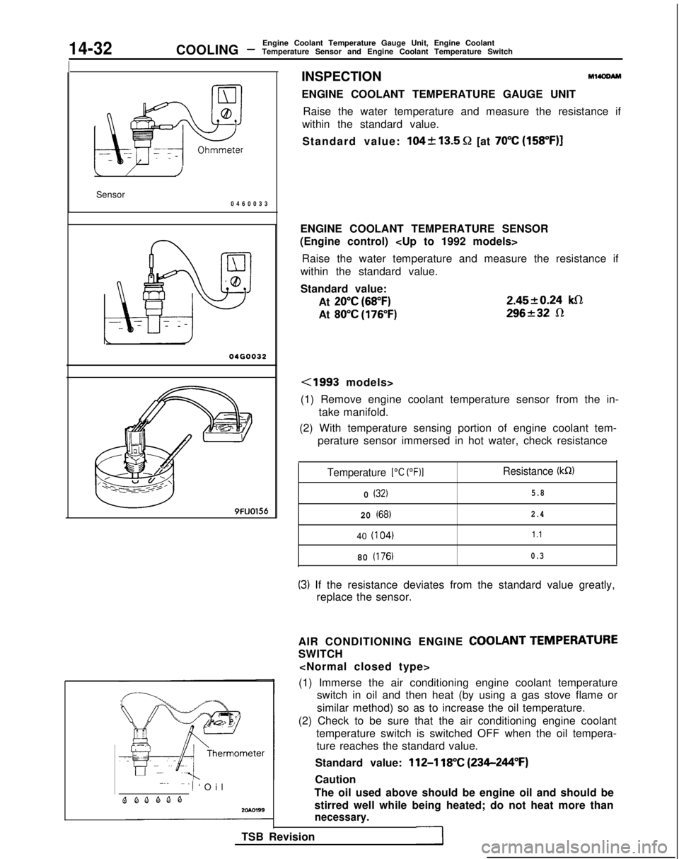
INSPECTIONM14OOAM
ENGINE COOLANT TEMPERATURE GAUGE UNIT
Raise the water temperature and measure the resistance if
within the standard value.
Standard value:
104k13.5 Q [at 70°C (158”F)]
ENGINE COOLANT TEMPERATURE SENSOR
(Engine control)
Raise the water temperature and measure the resistance if
within the standard value.
Standard value:
At
20°C (68°F)
At 80°C (176°F) 2.4520.24
klR
296232 R
<1993 models>
(1) Remove engine coolant temperature sensor from the in- take manifold.
(2) With temperature sensing portion of engine coolant tem- perature sensor immersed in hot water, check resistance
Temperature 1°C (OF)1Resistance (kR)
0 (32)5.8
20 (68)2.4
40
(I
04)1.1
80 (176)0.3
(3) If the resistance deviates from the standard value greatly,
replace the sensor.
AIR CONDITIONING ENGINE
COOLANT TEMPERATURE
SWITCH
(1) Immerse the air conditioning engine coolant temperature switch in oil and then heat (by using a gas stove flame or
similar method) so as to increase the oil temperature.
(2) Check to be sure that the air conditioning engine coolant temperature switch is switched OFF when the oil tempera-ture reaches the standard value.
Standard value:
112-l 18°C (234-244°F)
Caution
The oil used above should be engine oil and should be
stirred well while being heated; do not heat more than
necessary.
TSB Revision
Page 585 of 1273
COOLING -Engine Coolant Temperature Gauge Unit, Engine Coolant
Temperature Sensor and Engine Coolant Temperature Switch14-33
20R0586
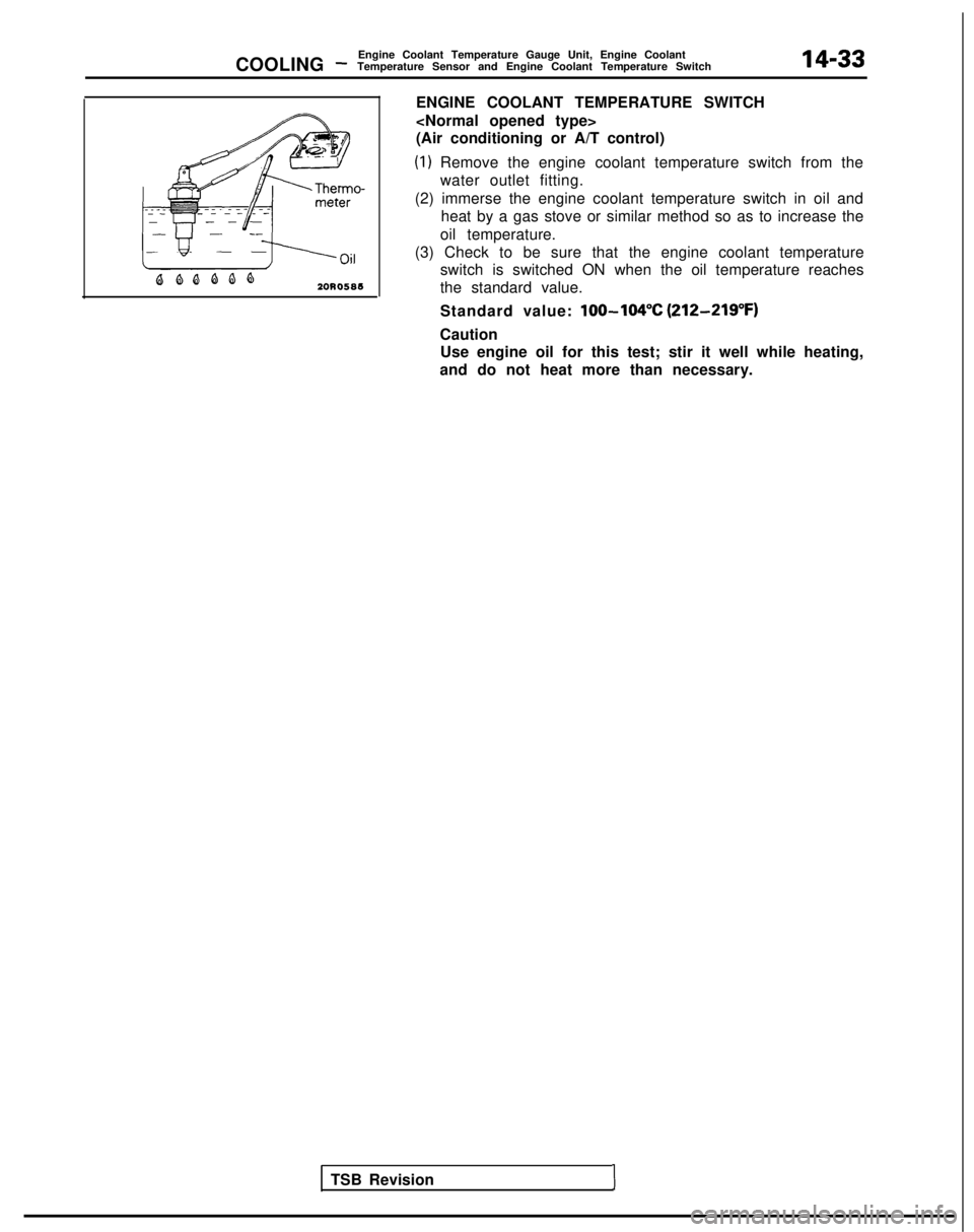
ENGINE COOLANT TEMPERATURE SWITCH
(Air conditioning or A/T control)
(1) Remove the engine coolant temperature switch from the
water outlet fitting.
(2) immerse the engine coolant temperature switch in oil and heat by a gas stove or similar method so as to increase the
oil temperature.
(3) Check to be sure that the engine coolant temperature switch is switched ON when the oil temperature reaches
the standard value.
Standard value:
lOO-104% (212-219°F)
CautionUse engine oil for this test; stir it well while heating,
and do not heat more than necessary.
TSB Revision
1
Page 588 of 1273
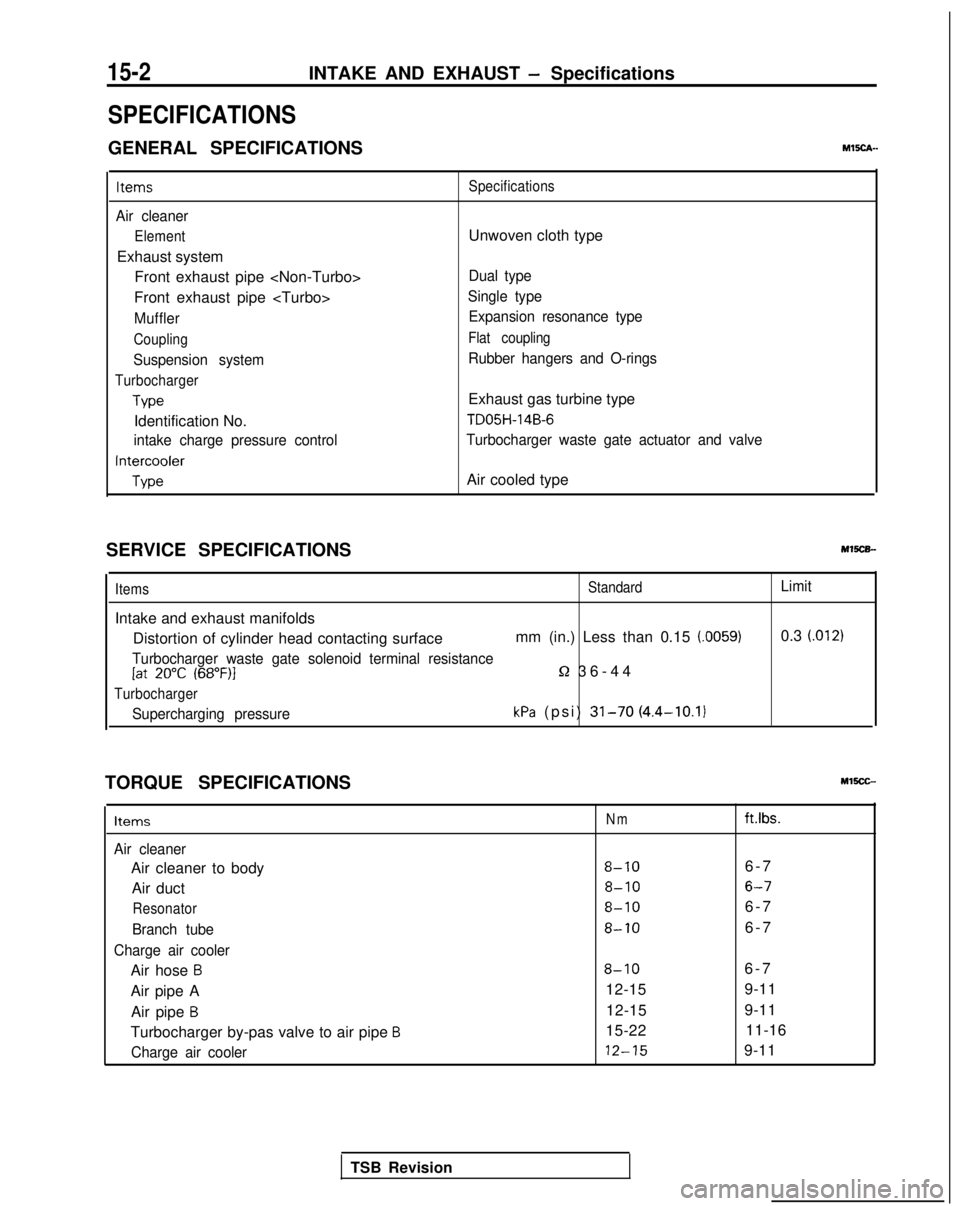
15-2INTAKE AND EXHAUST - Specifications
SPECIFICATIONS
GENERAL SPECIFICATIONSMEch-
Items
Air cleaner
Element
Exhaust systemFront exhaust pipe
Front exhaust pipe
Muffler
Coupling
Suspension system
Turbocharger
Type
Identification No.
intake charge pressure control
Intercooler
Type Specifications
Unwoven cloth type
Dual type
Single type Expansion resonance type
Flat coupling
Rubber hangers and O-rings
Exhaust gas turbine type
TD05H-14B-6
Turbocharger waste gate actuator and valve
Air cooled type
SERVICE SPECIFICATIONS
Items
Intake and exhaust manifolds
StandardLimit
Distortion of cylinder head contacting surface mm (in.) Less than 0.15 (0059)0.3 (.012)
Turbocharger waste gate solenoid terminal resistance[at 20°C (68”F)l5-2 36-4
4
Turbocharger
Supercharging pressurekPa (psi) 31-70 (4.4-10.1)
TORQUE SPECIFICATIONS
Items
Air cleaner
Air cleaner to body
Air duct
Resonator
Branch tube
Charge air cooler
Air hose B
Air pipe A Air pipe
B
Turbocharger by-pas valve to air pipe B
Charge air cooler
Nmft.lbs.
8-106-
7
8-106-7
8-106-
7
8-106-
7
8-106-
7
12-15 9-11
12-15 9-11
15-22 11-16 12-15
9-11
TSB Revision
Page 622 of 1273
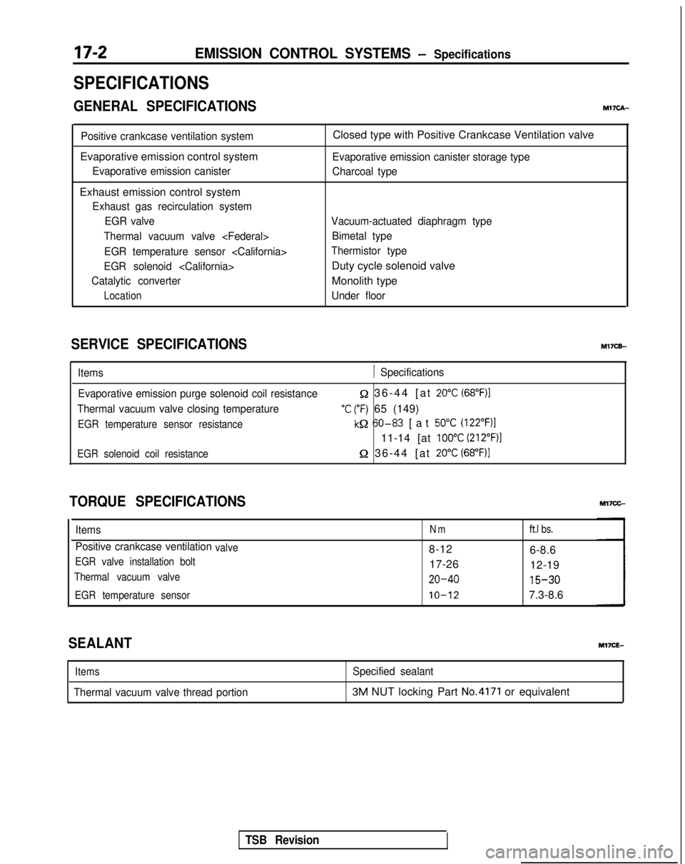
17-2EMISSION CONTROL SYSTEMS - Specifications
SPECIFICATIONS
GENERAL SPECIFICATIONSMl’IcA-
Positive crankcase ventilation system
Evaporative emission control system
Evaporative emission canister
Exhaust emission control system
Exhaust gas recirculation systemEGR valve
Thermal vacuum valve
EGR temperature sensor
EGR solenoid
Catalytic converter
Location
Closed type with Positive Crankcase Ventilation valve
Evaporative emission canister storage type
Charcoal type
Vacuum-actuated diaphragm type Bimetal type
Thermistor type
Duty cycle solenoid valve
Monolith type
Under floor
SERVICE SPECIFICATIONS M17CB-
Items1 Specifications
Evaporative emission purge solenoid coil resistance
Thermal vacuum valve closing temperature
EGR temperature sensor resistance
Q 36-44 [at 20°C (68”F)I
‘C (“F) 65 (149)
kQ 60-83
[at 50°C (122”F)l
11-14 [at 100°C (212”F)l
EGR solenoid coil resistance52 36-44 [at 20°C (68°F))
TORQUE SPECIFICATIONS
ItemsNmft.1 bs.
Positive crankcase ventilationvalve8-12
6-8.6
EGR valve installation bolt17-2612-19
Thermal vacuum valve20-40 15-30
EGR temperature sensorIO-127.3-8.6
SEALANT
Items
Thermal vacuum valve thread portion
Specified sealant3M NUT locking Part No.4171 or equivalent
TSB Revision