jump start MITSUBISHI GALANT 1989 Service Repair Manual
[x] Cancel search | Manufacturer: MITSUBISHI, Model Year: 1989, Model line: GALANT, Model: MITSUBISHI GALANT 1989Pages: 1273, PDF Size: 37.62 MB
Page 245 of 1273
FUEL SYSTEM
TSB Revision
---
I g$qfq, tcJ-s6FUO633
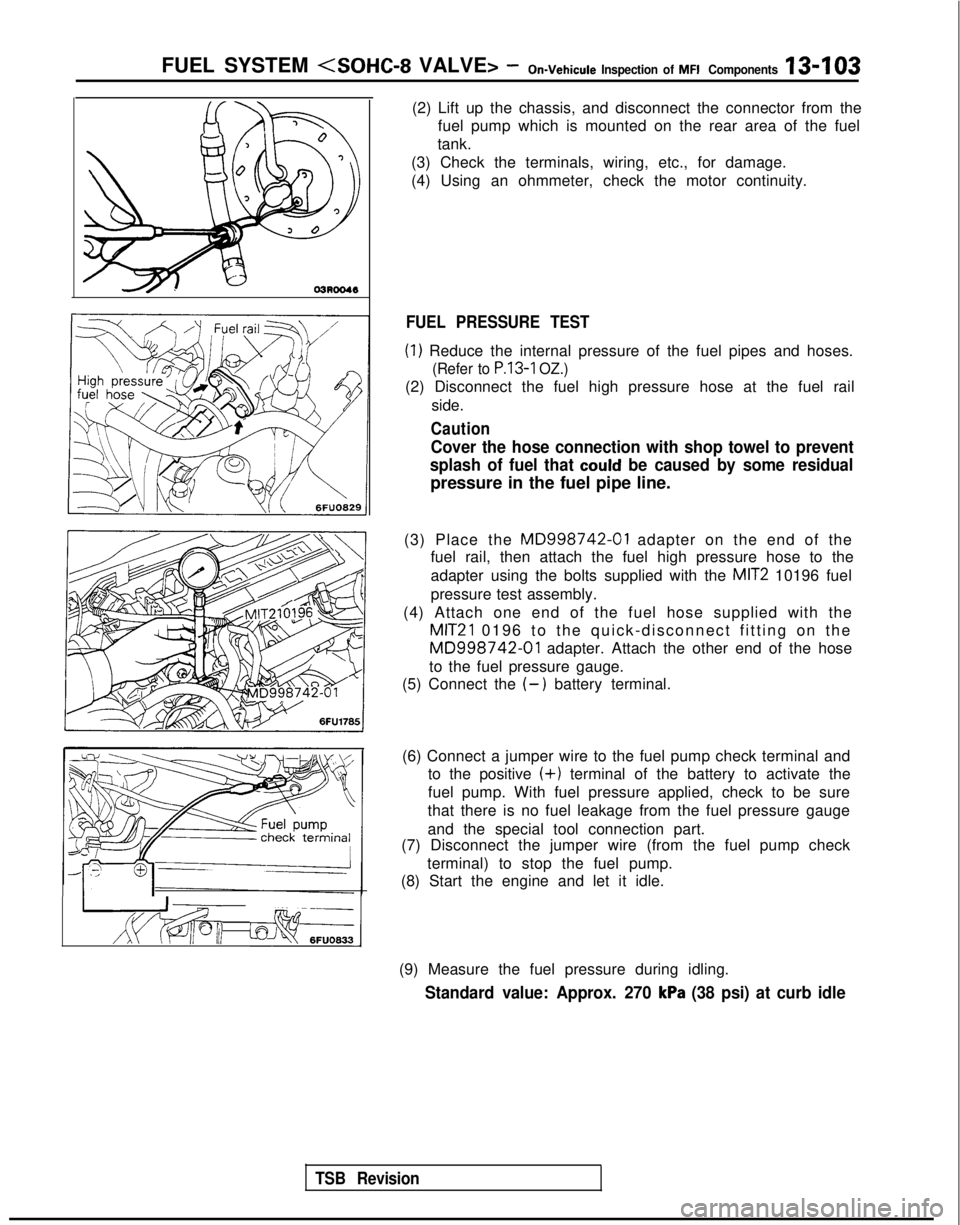
(2) Lift up the chassis, and disconnect the connector from the
fuel pump which is mounted on the rear area of the fuel
tank.
(3) Check the terminals, wiring, etc., for damage.
(4) Using an ohmmeter, check the motor continuity.
FUEL PRESSURE TEST
(1) Reduce the internal pressure of the fuel pipes and hoses.
(Refer to P.13-1 OZ.)
(2) Disconnect the fuel high pressure hose at the fuel rail
side.
Caution
Cover the hose connection with shop towel to prevent
splash of fuel that
could be caused by some residual
pressure in the fuel pipe line.
(3) Place the
MD998742-01 adapter on the end of the
fuel rail, then attach the fuel high pressure hose to the
adapter using the bolts supplied with the
MIT2 10196 fuel
pressure test assembly.
(4) Attach one end of the fuel hose supplied with the
MIT21 0196 to the quick-disconnect fitting on the
MD998742-01 adapter. Attach the other end of the hose
to the fuel pressure gauge.
(5) Connect the
(-) battery terminal.
(6) Connect a jumper wire to the fuel pump check terminal and to the positive
(+) terminal of the battery to activate the
fuel pump. With fuel pressure applied, check to be sure
that there is no fuel leakage from the fuel pressure gauge
and the special tool connection part.
(7) Disconnect the jumper wire (from the fuel pump check
terminal) to stop the fuel pump.
(8) Start the engine and let it idle.
(9) Measure the fuel pressure during idling.
Standard value: Approx. 270 kPa (38 psi) at curb idle
Page 277 of 1273
FUEL SYSTEM
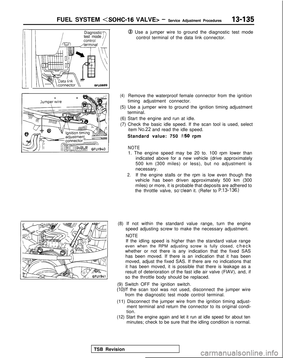
Diagnostictest mode@ Use a jumper wire to ground the diagnostic test mode
control terminal of the data link connector.
TSB Revision
(4)Remove the waterproof female connector from the ignition
timing adjustment connector.
(5) Use a jumper wire to ground the ignition timing adjustment terminal.
(6) Start the engine and run at idle.
(7) Check the basic idle speed. If the scan tool is used, select item
No.22 and read the idle speed.
Standard value: 750
*50 rpm
NOTE
1. The engine speed may be 20 to. 100 rpm lower than indicated above for a new vehicle (drive approximately
500 km (300 miles) or less), but no adjustment is
necessary.
2.If the engine stalls or the rpm is low even though the
vehicle has been driven approximately 500 km (300 miles) or more, it is probable that deposits are adhered to
the throttle valve, so’clean
it. (Refer to
P.13-136.)
(8) If not within the standard value range, turn the engine
speed adjusting screw to make the necessary adjustment.
NOTE
If the idling speed is higher than the standard value range
even when the RPM adjusting screw is fully closed, chec
k
whether or not there is any indication that the fixed SAS has been moved. If there is an indication that it has been
moved, adjust the fixed SAS. If there are no indications that
it has been moved, it is possible that there is leakage as a
result of deterioration of the fast idle air valve (FIAV), and, if
so the throttle body should be replaced.
(9) Switch OFF the ignition switch. (lO)lf
the scan tool was not used, disconnect the jumper wire
from the diagnostic test mode control terminal.
(11) Disconnect the jumper wire from the ignition timing adjust- ment terminal and return the connector to its original condi-
tion.
(12) Start the engine again and let it run at idle speed for about ten\
minutes; check to be sure that the idling condition is normal.
Page 278 of 1273
13-136FUEL SYSTEM
TPS connector
7FUO629
THROTTLE BODY (THROTTLE VALVE AREA)
CLEANINGMl3Rcv
(1)Start the engine and warm it up until the engine coolant is
heated to
80°C (176°F) or higher and then stop the engine.
(2)Remove the air intake hose from the throttle body.
(3)Plug the bypass passage inlet of the throttle body.
Caution
Do not allow cleaning solvent to enter the bypass
passage.
(4)Spray cleaning solvent into the valve through the throttle
body intake port and leave it for about 5 minutes.
(5)Start the engine, race it several times and idle it for about 1 minute. If the idling speed becomes unstable (or if the
engine stalls) due to the bypass passage being plugged,
slightly open the throttle valve to keep the engine
running.
(6)If the throttle valve deposits are not removed, repeat steps
(4) and (5).
(7)Unplug the bypass passage inlet.
(8)Attach the air intake hose.
(9)Use the scan tool to erase the diagnostic trouble code.
(10) Adjust the basic idle speed. (Refer to
P.13-134.)
NOTE
If the engrne hunts when idling after adjustment of the basic
idle speed, remove the
@ cable from the battery for 10
seconds or more, and then run the engine at idle again.
CLOSED THROTTLE POSITION SWITCH AND
THROTTLE POSITION SENSOR ADJUSTMEy,zIFF
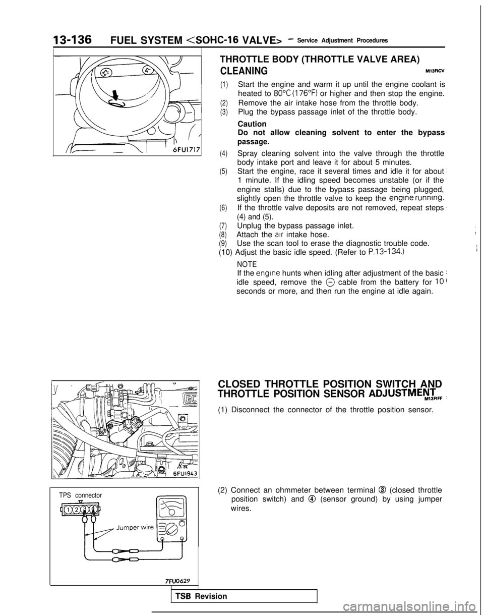
(1) Disconnect the connector of the throttle position sensor.
(2) Connect an ohmmeter between terminal
@I (closed throttle
position switch) and
@ (sensor ground) by using jumper
wires.
TSB Revision
Page 389 of 1273
FUEL SYSTEM
NOTE
For rpm, one-half of the actual engine rpm is indicated,
so the actual engine rpm in two times the indicated
value shown by the tachometer.
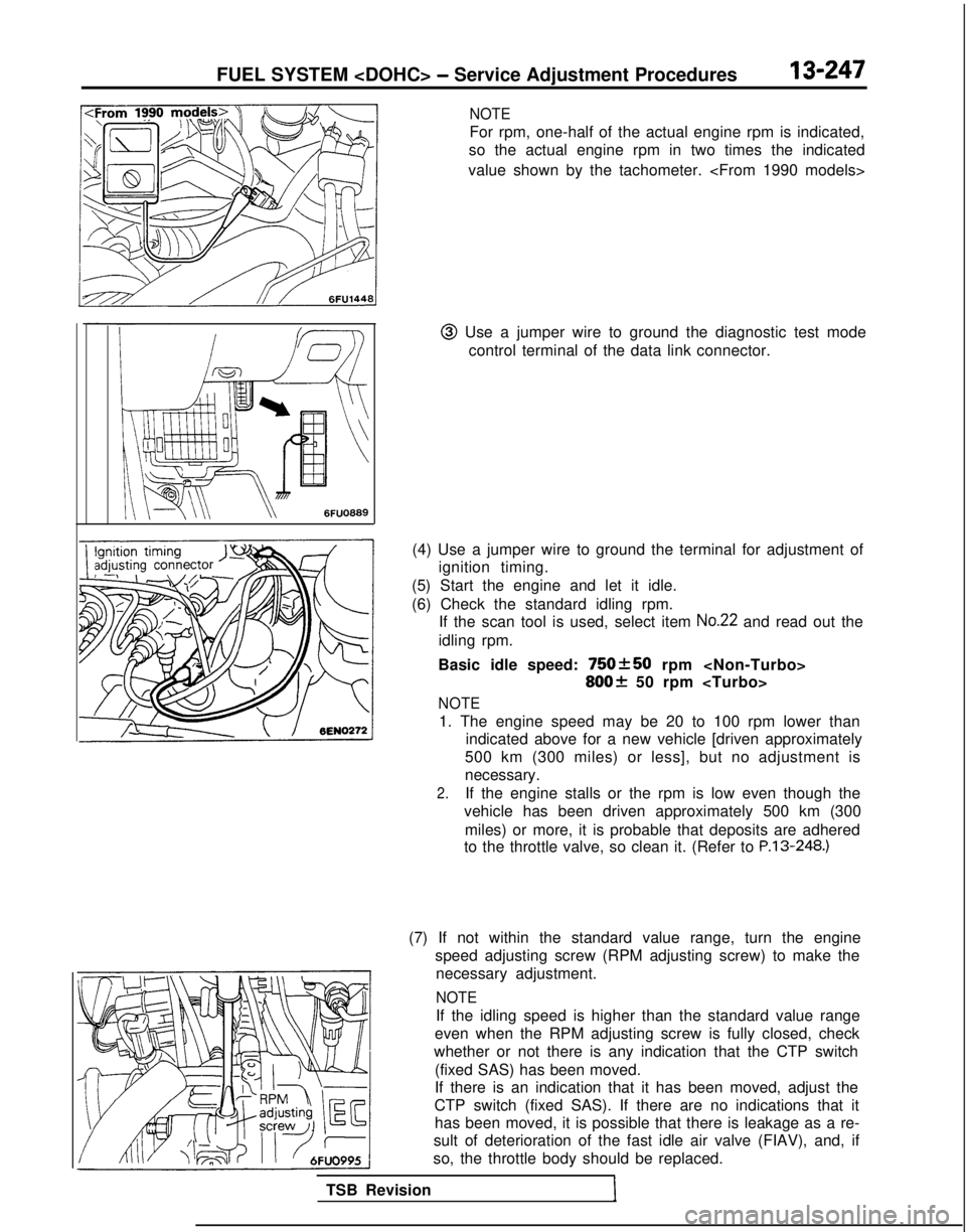
@I Use a jumper wire to ground the diagnostic test mode control terminal of the data link connector.
(4) Use a jumper wire to ground the terminal for adjustment of ignition timing.
(5) Start the engine and let it idle.
(6) Check the standard idling rpm. If the scan tool is used, select item
No.22 and read out the
idling rpm.
Basic idle speed:
750+50 rpm
800f 50 rpm
NOTE
1. The engine speed may be 20 to 100 rpm lower than indicated above for a new vehicle [driven approximately
500 km (300 miles) or less], but no adjustment is
necessary.
2.If the engine stalls or the rpm is low even though the
vehicle has been driven approximately 500 km (300
miles) or more, it is probable that deposits are adhered
to the throttle valve, so clean it. (Refer to P.13-248.)
TSB Revision
1
(7) If not within the standard value range, turn the engine speed adjusting screw (RPM adjusting screw) to make thenecessary adjustment.
NOTE
If the idling speed is higher than the standard value range
even when the RPM adjusting screw is fully closed, check
whether or not there is any indication that the CTP switch
(fixed SAS) has been moved.
If there is an indication that it has been moved, adjust the
CTP switch (fixed SAS). If there are no indications that it has been moved, it is possible that there is leakage as a re-
sult of deterioration of the fast idle air valve (FIAV), and, if
so, the throttle body should be replaced.
Page 390 of 1273
13-248FUEL SYSTEM
(8) Switch OFF the ignition switch.
(9) If the scan tool was not used, disconnect the jumper wire from the diagnostic test mode control terminal. (10)Disconnect
the jumper wire from the terminal for adjust-
ment of ignition timing, and return the connector to its
original condition.
(11
)Start the engine again and let it run at idle speed for about
ten minutes; check to be sure that the idling condition is
normal.
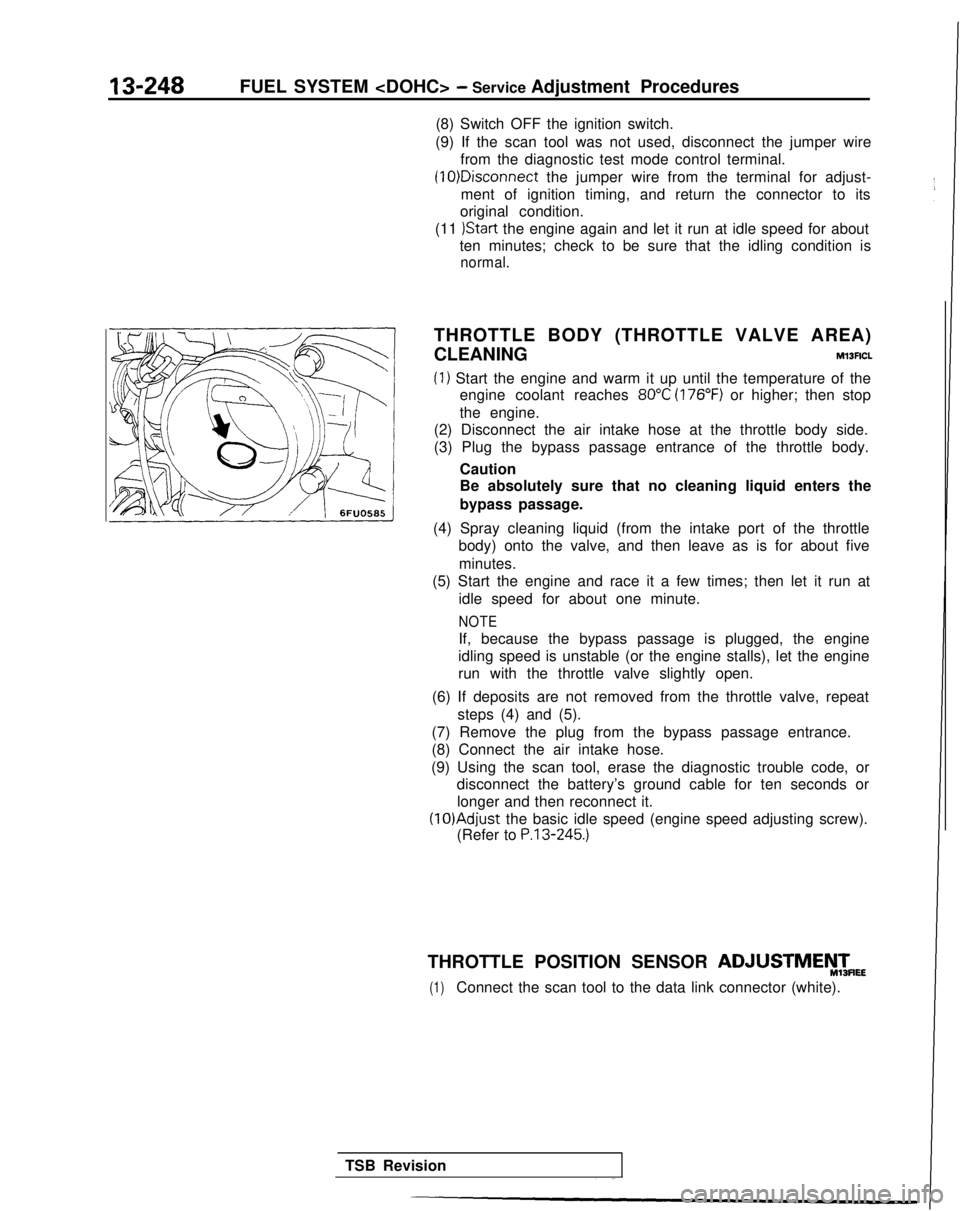
THROTTLE BODY (THROTTLE VALVE AREA)
CLEANING
Ml3ACL
(1) Start the engine and warm it up until the temperature of the engine coolant reaches
80°C (176°F) or higher; then stop
the engine.
(2) Disconnect the air intake hose at the throttle body side.
(3) Plug the bypass passage entrance of the throttle body.
Caution
Be absolutely sure that no cleaning liquid enters the
bypass passage.
(4) Spray cleaning liquid (from the intake port of the throttle body) onto the valve, and then leave as is for about five
minutes.
(5) Start the engine and race it a few times; then let it run at
idle speed for about one minute.
NOTE
If, because the bypass passage is plugged, the engine
idling speed is unstable (or the engine stalls), let the engine
run with the throttle valve slightly open.
(6) If deposits are not removed from the throttle valve, repeat steps (4) and (5).
(7) Remove the plug from the bypass passage entrance.
(8) Connect the air intake hose.
(9) Using the scan tool, erase the diagnostic trouble code, or disconnect the battery’s ground cable for ten seconds or
longer and then reconnect it. (lO)Adjust
the basic idle speed (engine speed adjusting screw).
(Refer to
P.13-245.)
THROTTLE POSITION SENSOR ADJUSTMEyTmEE
(1)Connect the scan tool to the data link connector (white).
TSB Revision
Page 454 of 1273
13-312FUEL SYSTEM
of
MFI
Components
FUEL PRESSURE TESTMxwXAAe
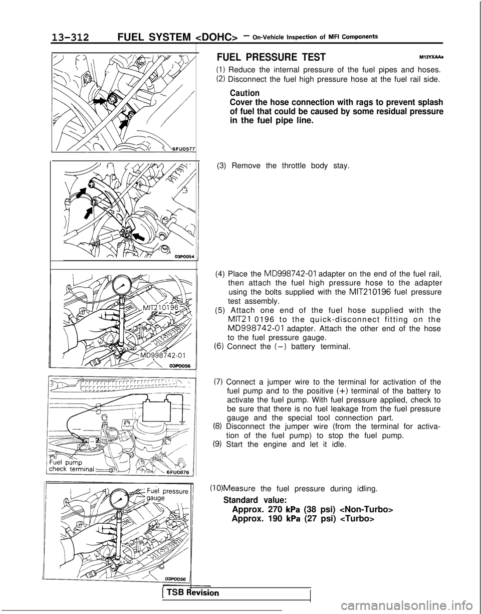
(1) Reduce the internal pressure of the fuel pipes and hoses.
(2) Disconnect the fuel high pressure hose at the fuel rail side.
Caution
Cover the hose connection with rags to prevent splash
of fuel that could be caused by some residual pressure
in the fuel pipe line.
(3) Remove the throttle body stay.
(4) Place the MD998742-01
adapter on the end of the fuel rail,
then attach the fuel high pressure hose to the adapter
using the bolts supplied with the MIT210196
fuel pressure
test assembly.
(5) Attach one end of the fuel hose supplied with the
MIT21 0196 to the quick-disconnect fitting on the
MD998742-01 adapter. Attach the other end of the hose
to the fuel pressure gauge.
(6) Connect the (-) battery terminal.
(7) Connect a jumper wire to the terminal for activation of the fuel pump and to the positive
(+) terminal of the battery to
activate the fuel pump. With fuel pressure applied, check to
be sure that there is no fuel leakage from the fuel pressure
gauge and the special tool connection part.
(8) Disconnect the jumper wire (from the terminal for activa-
tion of the fuel pump) to stop the fuel pump.
(9) Start the engine and let it idle. (10)Measure
the fuel pressure during idling.
Standard value:
Approx. 270 kPa (38 psi)
Approx. 190
kPa (27 psi)
1 TSB Revision