wheel torque MITSUBISHI GALANT 1989 Service Repair Manual
[x] Cancel search | Manufacturer: MITSUBISHI, Model Year: 1989, Model line: GALANT, Model: MITSUBISHI GALANT 1989Pages: 1273, PDF Size: 37.62 MB
Page 3 of 1273
00-l
GENERAL
CONTENTS
GENERAL DATA AND SPECIFICATIONS.....23
HOWTOUSETHISMANUAL......................
3
Definition of Terms ......................................3
ExplanationofCircuitDiagrams..................7
Explanation of
ManualContents .................4
Explanation of the Troubleshooting
Guide .............................................................
6
Model
Indications .........................................3
Scope of Maintenance, Repair and
Servicing Explanations
..................................
3
Troubleshooting .............................................3
LUBRICATIONANDMAINTENANCE............
34
MAINTENANCE SERVICE............................... 39
AirCleanerElement
.....................................39
Automatic
Transaxle
.....................................43
Ball Joint and Steering Linkage Seals ........45
Brake Hoses................................................. 45
Disc Brake Pads ........................................... 44
Drive Belt (For Water Pump and
Generator) .......................................................
41
Drive
Shaft Boots .........................................45
Engine Coolant
............................................. 44
Engine Oil .....................................................
41
Engine Oil Filter ...........................................41
Exhaust System
............................................ 45
FuelHoses
...................................................39
Fuel System
.................................................39
Manual Transaxle ..........................................42
RearAxle......................................................45
Rear Drum Brake Linings and
RearWheel Cylinders
..................................44
Spark
Plugs...................................................40
Timing Belt...................................................40
MASTER
TROUBLESHOOTING.....................28
PRECAUTIONS
BEFORESERVICE................15
RECOMMENDED LUBRICANTS AND
LUBRICANT CAPACITIESTABLE..................35
SCHEDULED
MAINTENANCETABLE ...........38
SPECIAL HANDLING INSTRUCTIONS
FOR AWD MODELS
.......................................20
TABLE OF MAIN SEALANTS
AND
ADHESIVES ............................................46
TIGHTENING TORQUE
................................... 27
TOWING
ANDHOISTING ..............................17
VEHICLE
IDENTIFICATION .............................8
Chassis Number ...........................................
11
EngineModel
Stamping
...............................12
Theft Protection ............................................12
Vehicle Identification Code Chart Plate.......
8
Vehicle Identification Number List
..............8
Vehicle Identification Number Location .......
8
Vehicle Information
CodePlate...................1 1
Vehicle SafetyCertificationLabel................12
Page 765 of 1273
AUTOMATIC TRANSAXLE - Troubleshooting23-59
ring
brake
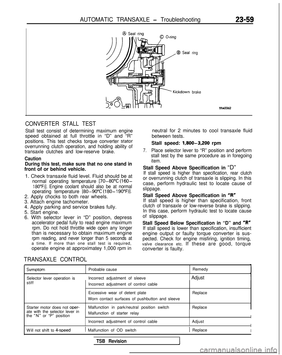
CONVERTER STALL TEST
Stall test consist of determining maximum engine
speed obtained at full throttle in “D” and “R”
positions. This test checks torque converter stator
overrunning clutch operation, and holding ability of
transaxle clutches and low-reserve brake.
Caution
During this test, make sure that no one stand in
front of or behind vehicle.
1. Check transaxle fluid level. Fluid should be at
normal operating temperature [70-80°C (160-
18O”F)j. Engine coolant should also be at normal
operating temperature
[80-90°C (180-19O”F)l.
2. Apply chocks to both rear wheels.
3. Attach engine tachometer.
4. Apply parking and service brakes fully.
5. Start engine.
6. With selector lever in “D” position, depress
accelerator pedal fully to read engine maximum
rpm. Do not hold throttle wide open any longer
than is necessary to obtain maximum engine
rpm reading, and never longer than 5 seconds at
a time. If more than one stall test is required,
operate engine at approximatey 1,000 rpm in
TRANSAXLE CONTROL
neutral for 2 minutes to cool transaxle fluid
between tests.
Stall speed: 1,800-3,200
rpm
7.Place selector lever to “R” position and perform
stall test by the same procedure as in foregoing
item.
Stall Speed Above Specification in “D”
If stall speed is higher than specification, rear clutch
or overrunning clutch of transaxle is slipping. In this
case, perform hydraulic test to locate cause of
slippage.
Stall Speed Above Specification in “I?”
If stall speed is higher than specification, front
clutch of transaxle or low-reverse brake is slipping. In this case, perform hydraulic test to locate cause
of slippage.
Stall Speed Below Specification in “D” and “R”
If stall speed is lower than specification, insufficient
engine output or faulty torque converter is sus-
pected. Check for engine misfiring, ignition timing,
valve clearance etc. If these are good, torque
converter is faulty. Svmotom
Probable cause
Remedy
Selector lever operation is Incorrect adjustment of sleeve
1 Adjust
stiff
Starter motor does not oper-
Incorrect adjustment of control cable
Excessive wear of detent plate
Worn contact surfaces of pushbutton and sleeve
Malfunction in park/neutral position switch Replace
Replace
ate with the selector lever in
the
“N” or “P” position Malfunction of starter relayI
Incorrect adjustment of control cable
AdjustI
W
ill not shift to 4-speed
( Malfunction of OD switch) ReplaceI
TSB Revision
Page 813 of 1273
AUTOMATIC TRANSAXLE - Transaxle Assembly
OSAOl82
Hub
SERVICE POINTS OF REMOVAL MZ3LMU
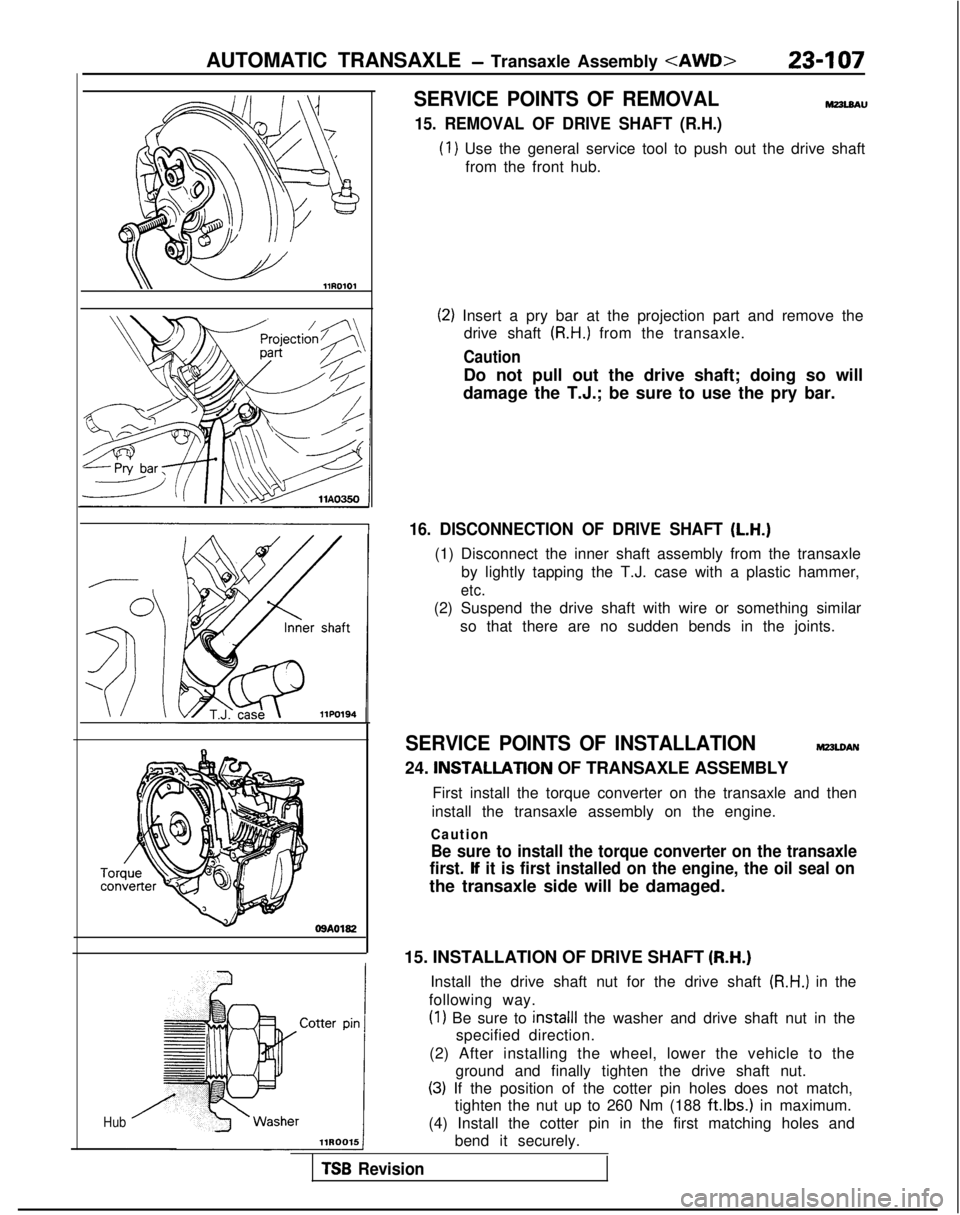
15. REMOVAL OF DRIVE SHAFT (R.H.)
(1) Use the general service tool to push out the drive shaft
from the front hub.
(2) Insert a pry bar at the projection part and remove the drive shaft
(R.H.) from the transaxle.
Caution
Do not pull out the drive shaft; doing so will
damage the T.J.; be sure to use the pry bar.
16. DISCONNECTION OF DRIVE SHAFT (L.H.)
(1) Disconnect the inner shaft assembly from the transaxle
by lightly tapping the T.J. case with a plastic hammer,
etc.
(2) Suspend the drive shaft with wire or something similarso that there are no sudden bends in the joints.
SERVICE POINTS OF INSTALLATIONMZ3LOAN
24. INSTALLAnON OF TRANSAXLE ASSEMBLY
First install the torque converter on the transaxle and then
install the transaxle assembly on the engine.
Caution
Be sure to install the torque converter on the transaxle
first.
lf it is first installed on the engine, the oil seal on
the transaxle side will be damaged.
15. INSTALLATION OF DRIVE SHAFT
(R-H.)
Install the drive shaft nut for the drive shaft (R.H.) in the
following way.
(1) Be sure to install1 the washer and drive shaft nut in the
specified direction.
(2) After installing the wheel, lower the vehicle to the ground and finally tighten the drive shaft nut.
(3) If the position of the cotter pin holes does not match,tighten the nut up to 260 Nm (188
ft.lbs.1 in maximum.
(4) Install the cotter pin in the first matching holes and bend it securely.
TSB Revision
Page 832 of 1273
26-2
SPECIFICATIONS
FRONT AXLE - Specifications
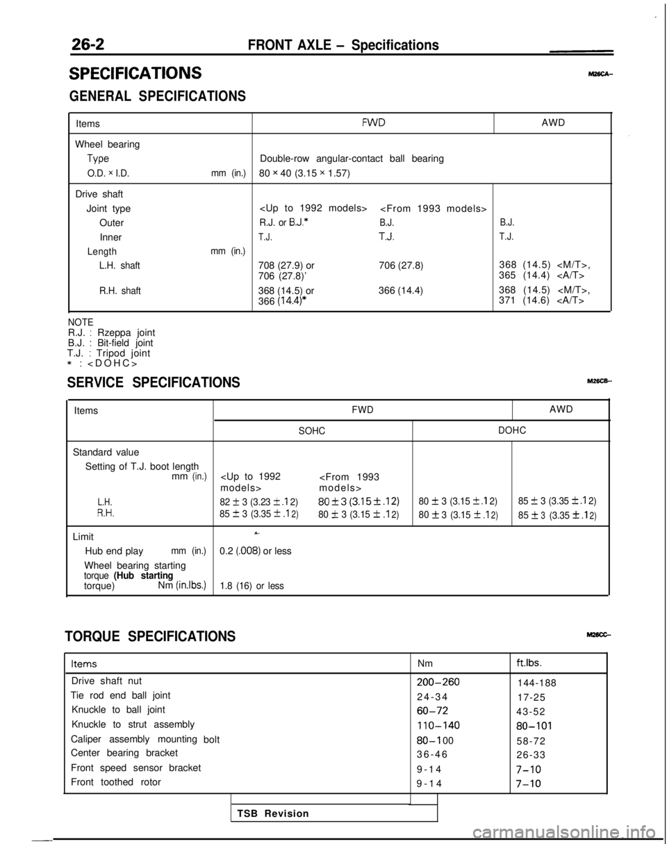
GENERAL SPECIFICATIONS
Items
Wheel bearing Type
O.D. x I.D.
Drive shaft
Joint type Outer
Inner
Length L.H. shaft
R.H. shaft
FWDAWD
Double-row angular-contact ball bearing
mm (in.)80 x 40 (3.15 x 1.57)
R.J. or B.J.*B.J. B.J.
T.J.T.J.T.J.
mm (in.)
708 (27.9) or
706 (27.8)368 (14.5)
706 (27.8)’ 365 (14.4)
368 (14.5) or 366 (14.4)368 (14.5)
366
(14.4)*371 (14.6)
NOTER.J. : Rzeppa joint
B.J. : Bit-field joint
T.J. : Tripod joint *:
>
SERVICE SPECIFICATIONS
ItemsFWDAWD
SOHC
DOHC
Standard value
Setting of T.J. boot length mm
(in.)
L.H.82 + 3 (3.23 k .I 2)80f3 (3.15f.12)80 + 3 (3.15 f .I 2)
85 f 3 (3.35 k .I 2)
R.H.85 III 3 (3.35 +
.I2)80 IL 3 (3.15 f.I2)80f3
(3.15f .I2)85f3(3.3531
.I2)
LimitX.
Hub end playmm (in.)0.2 (.008) or less
Wheel bearing starting
torque (Hub startingtorque) Nm (inlbs.)1.8 (16) or less
TORQUE SPECIFICATIONS
ItemsNmftlbs.
Drive shaft nut200-260144-188
Tie rod end ball joint 24-3
4
17-25
Knuckle to ball joint
60-7243-52
Knuckle to strut assembly
110-14080-101
Caliper assembly mounting bolt80-I 0058-72
Center bearing bracket 36-4
6
26-33
Front speed sensor bracket 9-14
7-10
Front toothed rotor9-1
4
7-10
TSB Revision
-_
Page 839 of 1273
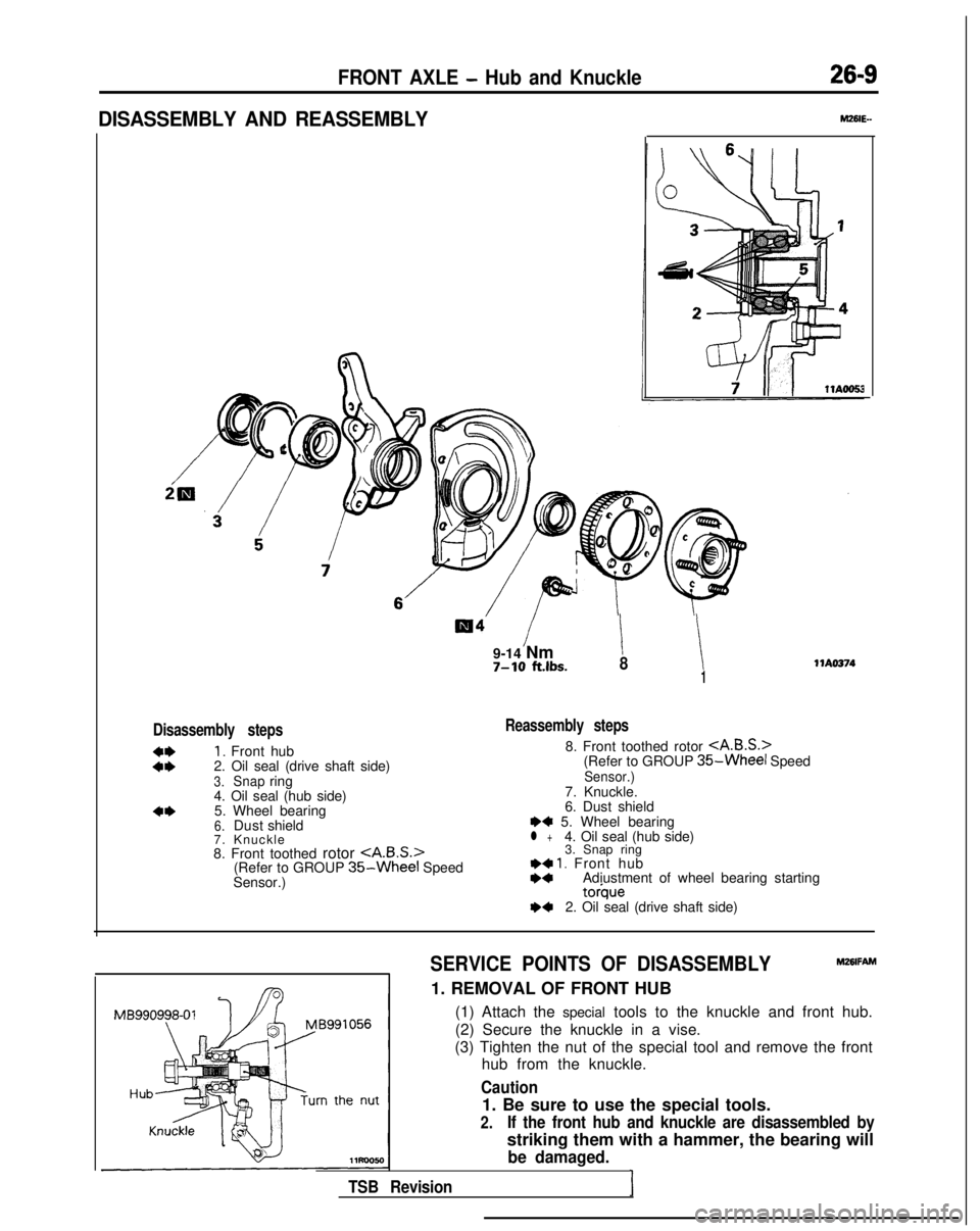
FRONT AXLE - Hub and Knuckle26-9
DISASSEMBLY AND REASSEMBLY
9-14 Nm7-10 ft.lbs.i !81
Disassembly steps
::
I. Front hub
2. Oil seal (drive shaft side)
3.Snapring
4. Oil seal (hub side)
4*5. Wheel bearing6.Dust shield
7. Knuckl
e
8. Front toothed rotor
(Refer to GROUP
35-Wheel Speed
Sensor.)
WA0374
Reassembly steps
8. Front toothed rotor
(Refer to GROUP 35-Wheel SpeedSensor.)7. Knuckle.
6. Dust shield
I)+ 5. Wheel bearingl +4. Oil seal (hub side) 3. Snap ring
I)+ 1. Front hubI)*Adiustment of wheel bearing starting torque
I)+2. Oil seal (drive shaft side)
SERVICE POINTS OF DISASSEMBLY
Mz6lFAM
1. REMOVAL OF FRONT HUB (1) Attach the special tools to the knuckle and front hub.
(2) Secure the knuckle in a vise.
(3) Tighten the nut of the special tool and remove the front hub from the knuckle.
Caution
1. Be sure to use the special tools.
2.If the front hub and knuckle are disassembled by
striking them with a hammer, the bearing will
be damaged.
TSB RevisionI
Page 841 of 1273

FRONT AXLE - Hub and Knuckle26-11
MB990883-0
1
I IUII12A0545
m
MB990847-01
MB990998-07
IMB99099&0 1
SERVICE POINTS OF REASSEMBLYM26lHAL
5. INSTALLATION OF WHEEL BEARING
(1) Fill the wheel bearing with multipurpose grease.
(2) Apply a thin coating of multipurpose grease to the knuckle and bearing contact surfaces.
(3) With the wheel bearing inner
race removed, press-in
the bearing by using the special tools.
(4) Install the wheel bearing inner race to the wheel
bearing.
4. INSTALLATION OF OIL SEAL (HUB SIDE)
(1) Drive the oil seal (hub side) into the knuckle by using
the special tools until it is flush with the knuckle end
surface.
(2) Apply multipurpose grease to the lip of the oil seal and
to the surfaces of the oil seal which contact the front
hub.
1. INSTALLATION OF FRONT HUB
(1) Use the special tool to mount the front hub assembly
onto the knuckle.
(2) Tighten the nut of the special tool to
200-260 Nm
(144- 188 ft.Ibs.).
(3) Rotate the front hub assembly in order to seat the
bearing.
(4) Leave the special tool in place and take the measure-
ments described below.
l ADJUSTMENT OF WHEEL BEARING STARTING
TORQUE
(1) Measure the wheel bearing starting torque (hub starting torque) by using the special tools.
Limit: 1.8 Nm (16
in.lbs.) or less
NOTE
The starting torque must be within the limit and, in addition, the bearing must not feel rough when
rotated.
TSB Revision
Page 861 of 1273
27-1
mnAA-
AXLE SHAFT...................................................17
DIFFERENTIAL CARRIER................................26
DRIVE SHAFT.................................................. 20
SERVICE ADJUSTMENT PROCEDURES.......
15
Gear OilLevelCheck ...................................15
Rear Axle Total Backlash Check.................15
Rear Wheel Bearing End Play Check.........15
Rear Wheel Bearing Rotation Sliding
Resistance Check .........................................16
REAR AXLE HUB
SPECIAL
TOOLS.............................................12
SPECIFICATIONS
.............................................10
GeneralSpecifications..................................10
Lubricants
......................................................11
Sealants
andAdhesives...............................12
Service Specifications...................................10
TorqueSpecifications
...................................11
TROUBLESHOOTING ......................................14
Axle Shaft
Grease leakage
Noise while wheels are rotating
Differential
Bearing noise while driving or coasting
Constant noise
Gear noise while coasting Gear noise while driving
Heat
Noise while turning
Oil leakage
Drive Shaft
Noise
. . . . . . . . . . . . . . . . . . . . . . . . . . . . . . . . . . . . . . . . . . . . . . . . . . . . . . . . .8
REAR AXLE HUB
. . . . . . . . . . . . . . . . . . . . .
SERVICE ADJUSTMENT PROCEDURES . . . . . . .h3
Rear Hub Rotary-Sliding Resistance
(Torque)Adjustment . . . . . . . . . . . . . . . . . . . . . . . . . . . . . . .\
. . . . . .5
Wheel Bearing End Play Adjustment . . . . . . . . . .3
SPECIAL
TOOLS. . . . . . . . . . . . . . . . . . . . . . . . . . . . . . . . . . . . . . . . . . . . .3
SPECIFICATIONS. . . . . . . . . . . . . . . . . . . . . . . . . . . . . . . . . . . . \
. . . . . . . . .2
General Specifications . . . . . . . .
.._.......................2
Service Specifications . .. . . . . . . . . . . . . . . . . . . . . . . . . . . . . . . . .2
Torque Specifications. . . . . . . . . . . . . . . . . . . . . . . . . . . . . . . . . . .2
TROUBLESHOOtING. . . . . . . . . . . . . . . . . . . . . . . . . . . . . . . . . . . . \
. .2
Abnormal Sound
Page 863 of 1273
REAR AXLE
SPECIAL TOOLS
MZ7VA-A
ToolNumber
GENERAL
SERVICE TOOL
NameUse
Bearing and oil sealinstaller setInstallation of outer bearing outer race
Installation of inner bearing outer race Installation of oil seal
M B990938-01Handle
MB990890-01Bushing removerand installer baseInstallation of the drive gear
OPTIONAL: AVAIlABLE FROM O.T.C.
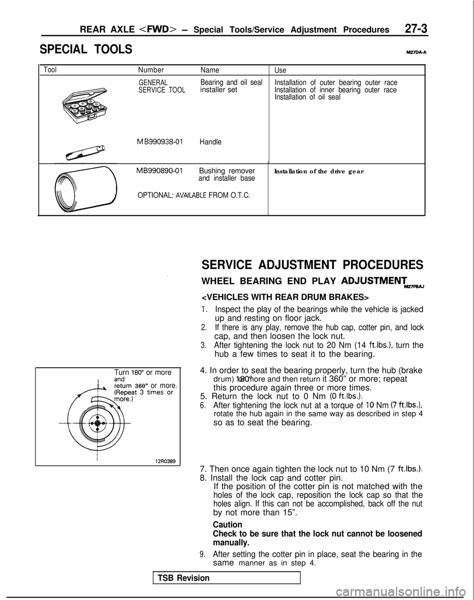
Turn 180” or more
360” or more.
SERVICE ADJUSTMENT PROCEDURES
WHEEL BEARING END PLAY ADJUSTMENTmw
1.Inspect the play of the bearings while the vehicle is jacked
up and resting on floor jack.
2.If there is any play, remove the hub cap, cotter pin, and lock
cap, and then loosen the lock nut.
3.After tightening the lock nut to 20 Nm (14 ft.lbs.1, turn the
hub a few times to seat it to the bearing.
4. In order to seat the bearing properly, turn the hub (brake drum) 180” or more and then return it 360” or more; repeat
this procedure again three or more times.
5. Return the lock nut to 0 Nm
(0 ft.lbs.).
6.After tightening the lock nut at a torque of 10 Nm (7 ft.lbs.1,
rotate the hub again in the same way as described in step 4
so as to seat the bearing.
7. Then once again tighten the lock nut to 10 Nm (7
ft.lbs.).
8. Install the lock cap and cotter pin. If the position of the cotter pin is not matched with the
holes of the lock cap, reposition the lock cap so that the
holes align. If this can not be accomplished, back off the nut
by not more than 15”.
Caution
Check to be sure that the lock nut cannot be loosened
manually.
9.After setting the cotter pin in place, seat the bearing in the
same manner as in step 4.
TSB Revision
Page 864 of 1273
27-4REAR AXLE
11 PO033
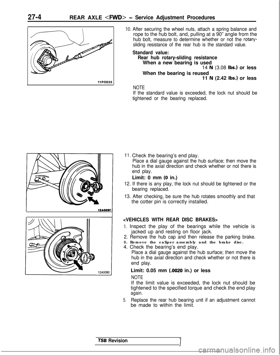
10. After securing the wheel nuts, attach a spring balance and
rope to the hub bolt, and, pulling at a 90” angle from the
hub bolt, measure to determine whether or not the rotary-
sliding resistance of the rear hub is the standard value.
Standard value: Rear hub rotary-sliding resistance
When a new bearing is used 14
N (3.08 Ibs.) or less
When the bearing is reused 11
N (2.42 Ibs.) or less
NOTE
If the standard value is exceeded, the lock nut should be
tightened or the bearing replaced.
11. Check the bearing’s end play.
Place a dial gauge against the hub surface; then move the
hub in the axial direction and check whether or not there is
end play.
Limit: 0 mm (0 in.)
12. If there is any play, the lock nut should be tightened or the
bearing replaced.
13. After checking, be sure the hub rotates smoothly and that
the cotter pin is correctly installed.
1. Inspect the play of the bearings while the vehicle is jacked up and resting on floor jack.
2. Remove the hub cap and then release the parking brake.
3. Remove the caliper assembly and the brake disc.
4. Check the bearing’s end play.
Place a dial gauge against the hub surface; then move the
hub in the axial direction and check whether or not there is
end play.
Limit: 0.05 mm (.0020 in.) or less
NOTE
If the limit value is exceeded, the lock nut should be
tightened to the specified torque and check the end play
again.
5.Replace the rear hub bearing unit if an adjustment cannot
be made to within the limit.
TSB RevisionI
Page 871 of 1273
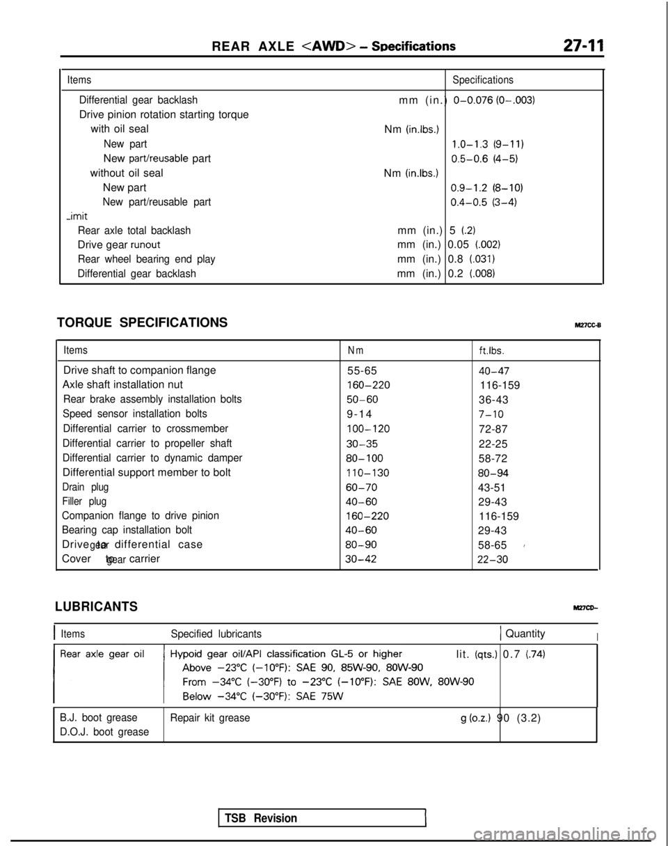
REAR AXLE
Items
Differential gear backlash
Drive pinion rotation starting torque
with oil seal
New part
New part/reusable part
without oil seal New part
New part/reusable part -imit
Rear axle total backlash
Drive gear runout
Rear wheel bearing end play
Differential gear backlash
Specifications
mm (in.) O-0.076 (O-.003)
Nm (in.lbs.) 1.0-1.3
(9-11)
0.5-0.6
(4-5)
Nm
(in.lbs.1 0.9-1.2
(8-10)
0.4-0.5
(3-4)
mm (in.) 5
(2)
mm (in.) 0.05 (.002)
mm (in.) 0.8 (.031)
mm (in.) 0.2 (008)
TORQUE SPECIFICATIONSM27cc-B
ItemsNmft.lbs.
Drive shaft to companion flange 55-6540-47
Axle shaft installation nut 160-220
116-159
Rear brake assembly installation bolts50-6036-43
Speed sensor installation bolts9-1
4
7-10
Differential carrier to crossmember
100-120
72-87
Differential carrier to propeller shaft30-3522-25
Differential carrier to dynamic damper80- 10058-72
Differential support member to bolt 110-130
80-94
Drain plug60-7043-51
Filler plug40-6029-43
Companion flange to drive pinion
160-220
116-159
Bearing cap installation bolt40-6029-43
Drive to differential case
gear80-9058-651
Cover to carriergear30-4222-30
TSB Revision
LUBRICANTS
IItemsSpecified lubricants1 QuantityI
lit. (qts.) 0.7 (74)
B.J. boot grease Repair kit grease
g (oz.) 90 (3.2)
D.O.J. boot grease