seat MITSUBISHI GALANT 1989 Service Repair Manual
[x] Cancel search | Manufacturer: MITSUBISHI, Model Year: 1989, Model line: GALANT, Model: MITSUBISHI GALANT 1989Pages: 1273, PDF Size: 37.62 MB
Page 10 of 1273
00-8GENERAL - Vehicle Identification
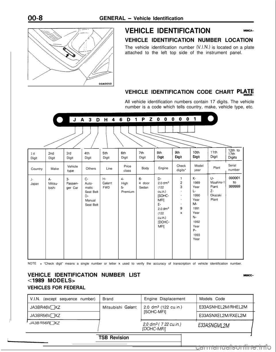
VEHICLE IDENTIFICATIONMOOCA-
VEHICLE IDENTIFICATION NUMBER LOCATION
The vehicle identification number
(V.I.N.) is located on a plate
attached to the left top side of the instrument panel.
/ OOAOOSO
VEHICLE IDENTIFICATION CODE CHART
P+zE
All vehicle identification numbers contain 17 digits. The vehiclenumber is a code which tells country, make, vehicle type, etc.
\ \\L\.u 5th 6th 7th
r\ 8th 9th 10th
Digit DigitDigitDigit Digit
Digit
I
3rdDigit
/
4thDigit
/ 2nd
Digit
Line
H- Galant
FWD
1 StDigit
Body
6-4 doorSedan
Price
class4-High5-Premium Engine
Check
digits*Model
year
Make Vehicle
typeOthersPlantSerialnumber
Country
OkazakiPlant
D-2.0 dm3(122cu.in.)[SOHC- MFI]
E-2.0 dm3(122cu.in.)[DOHC-
MFI]
K-1989
Year
L-1990
Year
M-1991Year
N-
1992
Year
P-1993Year
J-JapanA- Mitsu-
bishr
3- Passen-
9er
Car c-
Auto- matic
Seat Belt
D-Manual
Seat Belt
NOTEl “Check digit” means a single number or letter x used to verify the accuracy of transcription of vehicle identification \
number.
VEHICLE IDENTIFICATION NUMBER LIST
Mlmcc-
VEHICLES FOR FEDERAL
V.I.N. (except sequence number)BrandEngine Displacement Models Code
JA3BR46VnKZMitsubishi Galant
2.0 dm3 (122 cu.in.) E33ASNHEL2M/RHEL2M
JA3BR56VaKZ[SOHC-MFI]
E33ASNXEL2MlFiXEL2M
JA3B R56RaKZ
/
2.0
dm3
( 7 22 cu.in.) [DOHC-MFI]E33ASNGMLZM
TSB Revision
Page 26 of 1273
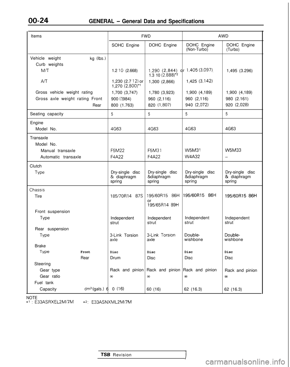
00-24GENERAL - General Data and Specifications
ItemsFWDAWD
SOHC Engine DOHC Engine DOHC Engine DOHC Engine
(Non-Turbo)
(Turbo)
Vehicle weight
kg (Ibs.)
Curb weightsMIT
1.2 10 (2.668)1.290 (2,844) or 1.405 (3.097).1,495 (3.296)1.3 10 (2.8881e2
/-v-r1,230 (2.7 12) or
1,300 (2,866) 1,425 (3.142)
1,270
(2.800)”
Gross vehicle weight rating 1,700 (3,747) 1,780 (3,923)1,900 (4,189)
1,900 (4,189)
Gross axle weight rating Front 900 (I ,984)
960 (2,116) 960 (2,116)
980 (2.161)
Rear800 (1.763)820 (1,807)940 (2.072)920 (2.028)
Seating capacity5 55 5
Engine
Model No.
4G634G63 4G634G63
Transaxle
Model No.Manual transaxle F5M22 F5M3
1 W5M31 W5M33
Automatic transaxle
F4A22F4A22 W4A32-
Clutch
Type
Dry-single disc
Dry-single disc
Dry-single disc Dry-single disc &
diaphragm & diaphragm & diaphragm &
diaphragm
spring spring spring
springChassis
Tire
185/7OR14 87s 195/60R15 86i-i 195/60R15 86ti195/60R15 86H
or
195/65R14 89H
Front suspension Type
Independent Independent
Independent
Independent
strut strut strut
strut
Rear suspension Type
3L$k Torsion3$k Torsion Double-
Double-
wishbone wishbone
Brake Type
Front
DiscDisc Disc
Disc
RearDrum
Disc Disc
Disc
Steering
Gear type Rack and pinion Rack and pinion Rack and pinion
Rack and pinion
Gear ratio
cc00m03
Fuel tank
Capacity
dm3(gals.) 60 (16)60 (16) 62 (16.3)
62 (16.3)
NOTE+’ : E33ASRXEL2Mi7M~2:
E33ASNXML2Mi7M
TSB RevisionI
Page 30 of 1273
00-28GENERAL - Tightening Torque/Master Troubleshooting
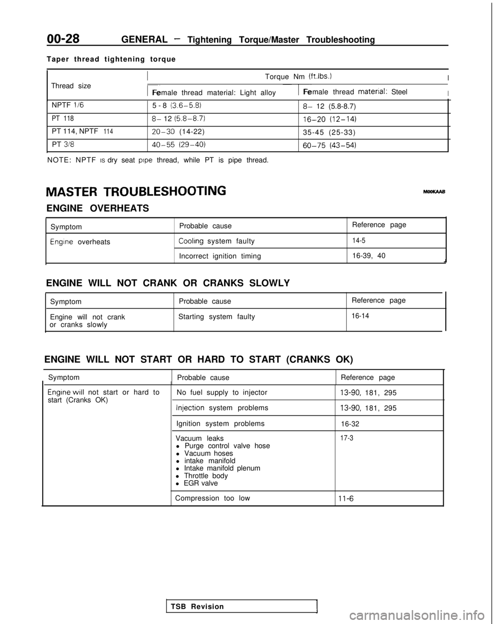
Taper thread tightening torque
Thread size
ITorque Nm (ftlbs.)I
r~Female thread material: Light alloy1-Female thread material: SteelI
NPTF II65-8 (3.6-5.8)
PT 1188- 12 (5.8-8.7)
PT 114, NPTF11420-30 (14-22)
PT
31840-55 (29-40)
NOTE: NPTF IS dry seat pope thread, while PT is pipe thread.
8- 12 (5.8-8.7)
16-20 (12-14)
35-45 (25-33)
60-75 (43-54)
MASTER TROUBLESHOOTING hlooKAAB
ENGINE OVERHEATS Symptom
Engine overheats Probable cause
Reference pageCoolrng system faulty14-5
Incorrect ignition timing
16-39, 40
ENGINE WILL NOT CRANK OR CRANKS SLOWLY Symptom Probable cause
Engine will not crank Starting system faulty
or cranks slowly Reference page
16-14
ENGINE WILL NOT START OR HARD TO START (CRANKS OK)
Symptom Probable cause Reference page
Engrne WIII not start or hard to
start (Cranks OK) No fuel supply to injector Injection
system problems
Ignition system problems
Vacuum leaks l Purge control valve hose
l Vacuum hoses
l intake manifold
l Intake manifold plenum
l Throttle body
l EGR valve13-90, 181, 295
13-90, 181, 295
16-32
17-3
Compression too low11-6
TSB Revision
Page 56 of 1273
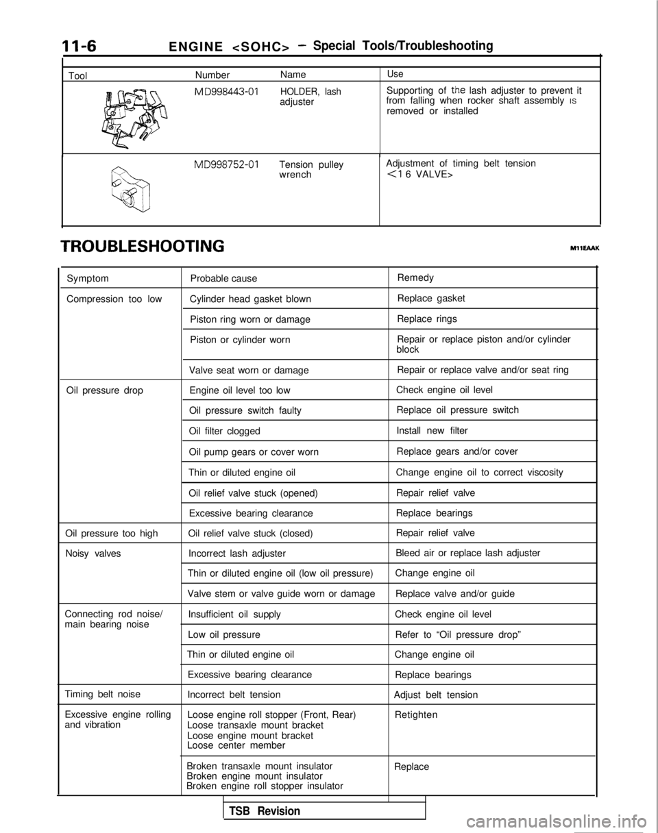
11-6
ToolENGINE
-Special Tools/Troubleshooting
Number
NameUse
M
D998443-01 HOLDER, lashSupporting of the lash adjuster to prevent it
adjuster from falling when rocker shaft assembly
IS
removed or installed MD998752-01
Tension pulley Adjustment of timing belt tension
wrench
TROUBLESHOOTINGMHEAAK
Symptom
Compression too low Probable cause
Cylinder head gasket blown Piston ring worn or damage
Piston or cylinder worn Remedy
Replace gasket
Replace rings
Repair or replace piston and/or cylinder
block
Valve seat worn or damage Repair or replace valve and/or seat ring
Oil pressure drop Engine oil level too low Check engine oil level
Oil pressure switch faulty Replace oil pressure switch
Oil filter clogged Install new filter
Oil pump gears or cover worn Replace gears and/or cover
Thin or diluted engine oil Change engine oil to correct viscosity
Oil relief valve stuck (opened) Repair relief valve
Excessive bearing clearance Replace bearings
Oil pressure too high Oil relief valve stuck (closed) Repair relief valve
Noisy valves Incorrect lash adjuster Bleed air or replace lash adjuster
Thin or diluted engine oil (low oil pressure) Change engine oil
Valve stem or valve guide worn or damage Replace valve and/or guide
Connecting rod noise/ Insufficient oil supply Check engine oil level
main bearing noise
Low oil pressure Refer to “Oil pressure drop”
Thin or diluted engine oil Change engine oil
Excessive bearing clearance Replace bearings
Timing belt noise Incorrect belt tension Adjust belt tension
Excessive engine rolling Loose engine roll stopper (Front, Rear)
and vibration Retighten
Loose transaxle mount bracket
Loose engine mount bracket
Loose center member
Broken transaxle mount insulator
Broken engine mount insulator
Broken engine roll stopper insulator Replace
TSB Revision
Page 60 of 1273
II-IOENGINE
(3) Remove the PCV hose from the PCV valve and attach a
vacuum gauge.
(4) Check that the negative pressure at the intake manifold
during idle revolution is normal.
Standard value:
(8 VALVE>Approx. 500 mmHg (20 in.Hg)
<16VALVE>Approx. 510 mmHg (20 in.Hg)
(5) If outside the standard value, isolate the cause by referring
to the following table and repair the fault.
Symptom
CauseRemed
y
l The vacuum gauge reading is less than l Ignition timing is retarded.l Adjust the ignition timing.
standard value, but the pointer is
stable.
l The vacuum gauge pointer swings l The gas mixture is excessivelyl Check
Multiport Fuel Injection
slowly.rich.system.
l The vacuum gauge pointer drops irre-
l The gas mixture is excessively
l Check
Multiport Fuel Injectiongularly.lean.system.
l The vacuum gauge pointer drops inter-
0 Incomplete close contact of in-0 Check and repair the valve.mittently to 30 to 160
mmHg
(1.2 to take and exhaust valve seats.
6.3 in.Hg).
l The vacuum gauge pointer drops sud-l Broken cylinder head gasketl ,Replace cylinder head gasket. denly
from the normal reading to 250 mmHg
(9.8 in.Hg). then returns to
normal.
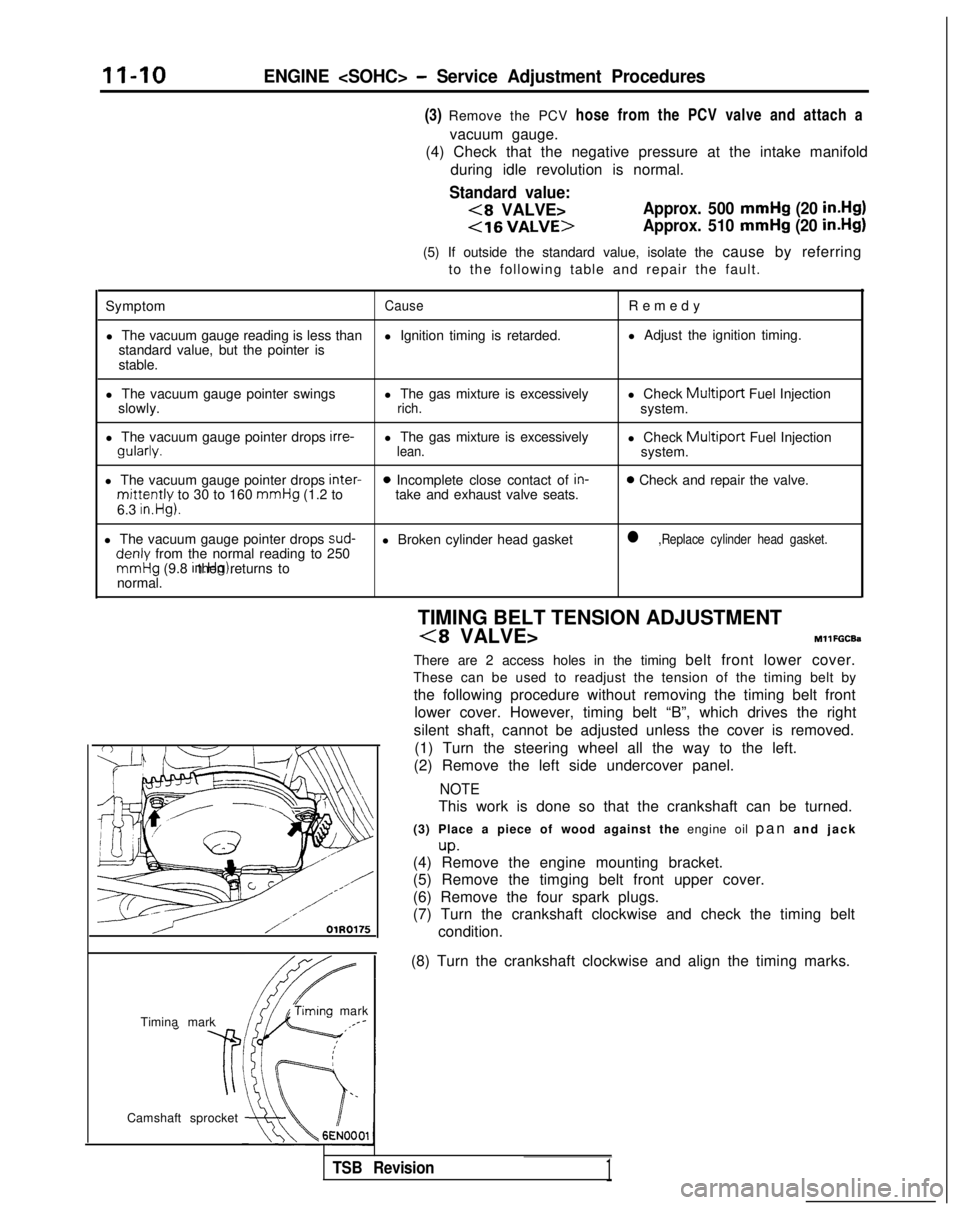
/ OlR0175
condition.
Timina mark
‘timing mark._*-
Camshaft sprocket TIMING BELT TENSION ADJUSTMENT
(8 VALVE>MllFGCEa
There are 2 access holes in the timing belt front lower cover.
These can be used to readjust the tension of the timing belt by
the following procedure without removing the timing belt front lower cover. However, timing belt “B”, which drives the right
silent shaft, cannot be adjusted unless the cover is removed. (1) Turn the steering wheel all the way to the left.
(2) Remove the left side undercover panel.
NOTE
This work is done so that the crankshaft can be turned.
(3) Place a piece of wood against the engine oil pan and jac
k
up.(4) Remove the engine mounting bracket.
(5) Remove the timging belt front upper cover.
(6) Remove the four spark plugs.
(7) Turn the crankshaft clockwise and check the timing belt
(8) Turn the crankshaft clockwise and align the timing marks.
TSB Revision1
Page 79 of 1273

ENGINE
Front of engine I)Intake side
6EN094
Exhaust side
OlR0391
Fuel rail
pr&surehose\0-nng
TSB Revision
(2) Using the special tool, tighten the bolts in the order
shown in two or three steps.
5. INSTALLATION OF RADIATOR UPPER HOSE
Align the mating marks (of the radiator hose and hoseclamp), and then, while applying force in the direction of
the arrow in the illustration, seat the hose clamp to the
trace marks (on the hose) remaining from the prior connection.
Caution Be sure to install the hose clamp at the trace marks (on
the hose) remaining from the prior connection.
3. CONNECTION OF FUEL HIGH PRESSURE HOSE
When connecting the high-pressure fuel hose to the fuel rail, apply a coating of engine oil to the hose union, and in-
sert so that the O-ring is not damaged.
Page 110 of 1273
II-60ENGINE
(9) If a cylinder’s compression pressure or pressure differenceis outside the limit, fill a small amount of engine oil through
the spark plug hole and repeat Items (7) and (8) above.
@ If the compression is increased when the oil is filled, the piston
and/or cylinder wall may be worn or
damaged.
@ If the compression is not Increased even though the oil is filled, the valve may be thermally seized, the valve
contact may be improper or pressure may leak at the
gasket. (10)Connect the connector of the crankshaft position sensor.
(1l)lnstall
the spark plug and spark plug cable.
(12)Erase the diagnostic trouble code with the scan tool or re-
connect the battery (-)
cable 10 seconds or more after it
was disconnected.
NOTE
This will erase the memory of the diagnostic trouble code which resulted from disconnection of the crankshaft posi-
tion sensor connector.
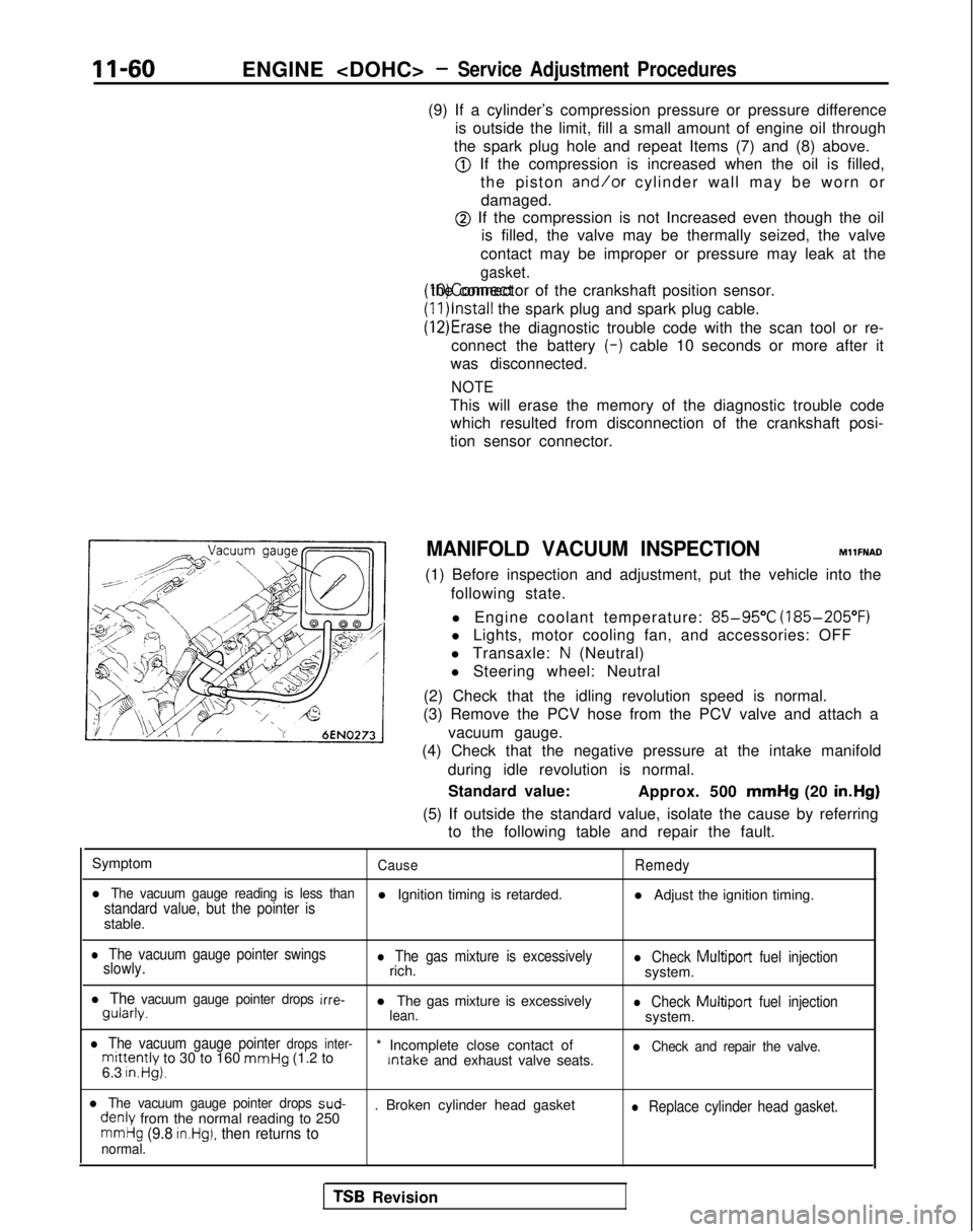
MANIFOLD VACUUM INSPECTION MllFNAD
(1) Before inspection and adjustment, put the vehicle into the following state.
l Engine coolant temperature:
85-95°C (185-205°F)
l Lights, motor cooling fan, and accessories: OFF
l Transaxle:
N (Neutral)
l Steering wheel: Neutral
(2) Check that the idling revolution speed is normal.
(3) Remove the PCV hose from the PCV valve and attach a
vacuum gauge.
(4) Check that the negative pressure at the intake manifold
during idle revolution is normal.
Standard value: Approx. 500 mmHg
(20 in.Hg)
(5) If outside the standard value, isolate the cause by referring to the following table and repair the fault.
Symptom
CauseRemedy
l The vacuum gauge reading is less thanstandard value, but the pointer isl Ignition timing is retarded. l Adjust the ignition timing.
stable.
l The vacuum gauge pointer swings
slowly.l The gas mixture is excessivelyrich.l Check Multiport fuel injectionsystem.
l The vacuum gauge pointer drops irre- gularly.
l The gas mixture is excessively
lean.l Check Multiport
fuel injectionsystem.
l The vacuum gauge pointer drops inter-mittently to 30 to 160 mmHg
(1.2 to * Incomplete close contact of Intake
and exhaust valve seats.l Check and repair the valve.
6.3 in.Hg).
l The vacuum gauge pointer drops sud- denly
from the normal reading to 250 . Broken cylinder head gasketl Replace cylinder head gasket.
mmHg (9.8 in.Hg), then returns tonormal.
TSB Revision
Page 191 of 1273
FUEL SYSTEM
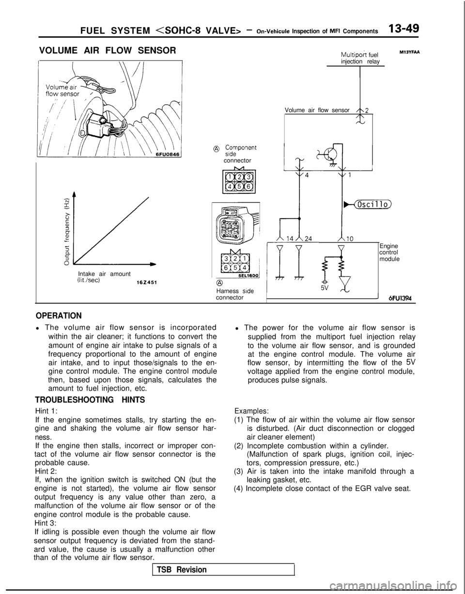
VOLUME AIR FLOW SENSOR
@ ;;vonent
connector
Intake air amount
(Wsec)162451
Multipoh fuel
injection relay
Volume air flow sensor
/\2/\N
Harness side
connector
IHjhcillo)
1.10
f-i5V
Engine
control
module
MlOYFAA
J 6FU1394
OPERATION
l The volume air flow sensor is incorporated
within the air cleaner; it functions to convert the
amount of engine air intake to pulse signals of a
frequency proportional to the amount of engine air intake, and to input those/signals to the en-
gine control module. The engine control module
then, based upon those signals, calculates the amount to fuel injection, etc.
TROUBLESHOOTING HINTS
Hint 1:
If the engine sometimes stalls, try starting the en-
gine and shaking the volume air flow sensor har-
ness.
If the engine then stalls, incorrect or improper con-
tact of the volume air flow sensor connector is the probable cause.
Hint 2:
If, when the ignition switch is switched ON (but the
engine is not started), the volume air flow sensor
output frequency is any value other than zero, a
malfunction of the volume air flow sensor or of the
engine control module is the probable cause. Hint 3:
If idling is possible even though the volume air flow
sensor output frequency is deviated from the stand-
ard value, the cause is usually a malfunction other
than of the volume air flow sensor. l The power for the volume air flow sensor is
supplied from the multiport fuel injection relay
to the volume air flow sensor, and is grounded at the engine control module. The volume air
flow sensor, by intermitting the flow of the
5V
voltage applied from the engine control module,
produces pulse signals.
Examples:
(1) The flow of air within the volume air flow sensor is disturbed. (Air duct disconnection or clogged
air cleaner element)
(2) Incomplete combustion within a cylinder. (Malfunction of spark plugs, ignition coil, injec-
tors, compression pressure, etc.)
(3) Air is taken into the intake manifold through a leaking gasket, etc.
(4) Incomplete close contact of the EGR valve seat.
TSB Revision
Page 207 of 1273
FUEL SYSTEM
(1) Improper adjustment of the basic idling speed.
(2) Deposits adhering to the ttirottle valve.
(3) Air being taken into the intake manifold due to a gasket leak, etc.
OPERATION
ISC motor position sensor is a variable resistor type,
and is integrated in the
ISC motor system. The slid-
ing pin of
ISC motor position sensor is in contact
with the end of the plunger. Therefore, as the plun- ger moves, the internal resistance of
ISC motor pos-
ition sensor varies. This leads to the variation of the (4) Improper seating of the EGR valve seat.
(5) lmcomplete combustion within a cylinder. (Mal-
function of spark plugs, ignition coil, injectors,
compression pressure, etc.)
the plunger position of the
ISC motor system, and
sends the signal to ECM. ECM processes the
ISC
motor position sensor signal, idle signal, coolant
temperature signal, load signal (A/T &
A/C) and ve-
hicle speed signal to control the opening angle of
the throttle valve and revolution speed during
en-
output voltage. ISC motor position sensor detects gine idling.
TROUBLESHOOTING HINTS
Since idling is not controlled when ISC motor posi-
tion sensor is troubled, idling may not be evenly
maintained.
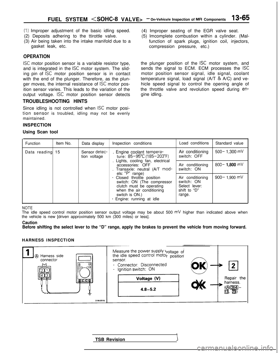
INSPECTION
Using Scan tool
FunctionItem No. Data display Inspection conditions Load conditions
Standard value
Data reading 15 Sensor detec-
. Engine coolant tempera-
Air conditioning 500- 1,300 mV
tion voltage
ture: 85-95’C (185-203°F)
switch: OFF
. Lights, cooling fan, electrical accessories: OFF Air conditioning 800-
1,800 mV. Transaxle: neutral (A/T
mod-
switch: ON
els: “P”
range)
1 Closed throttle position Air conditioning900- 1,900 mVswitch: ON (The compressorswitch: ON
clutch must be operating Select lever:
when the air conditioning shift to “D”
switch is ON.)
range.* Engine: running at idle
NOTEThe idle speed control motor position sensor output voltage may be about\
500 mV higher than indicated above when
the vehicle is new [driven approximately 500 km (300 miles) or less].
CautionBefore shifting the select lever to the “D” range, apply the brake\
s to prevent the vehicle from moving forward.
HARNESS INSPECTION
Measure the power supply voltage of
the idle speed control motor position
ei;;;it;;sco$ected
__...._ -.-
TSB Revision
Page 232 of 1273
13-90 FUEL SYSTEM
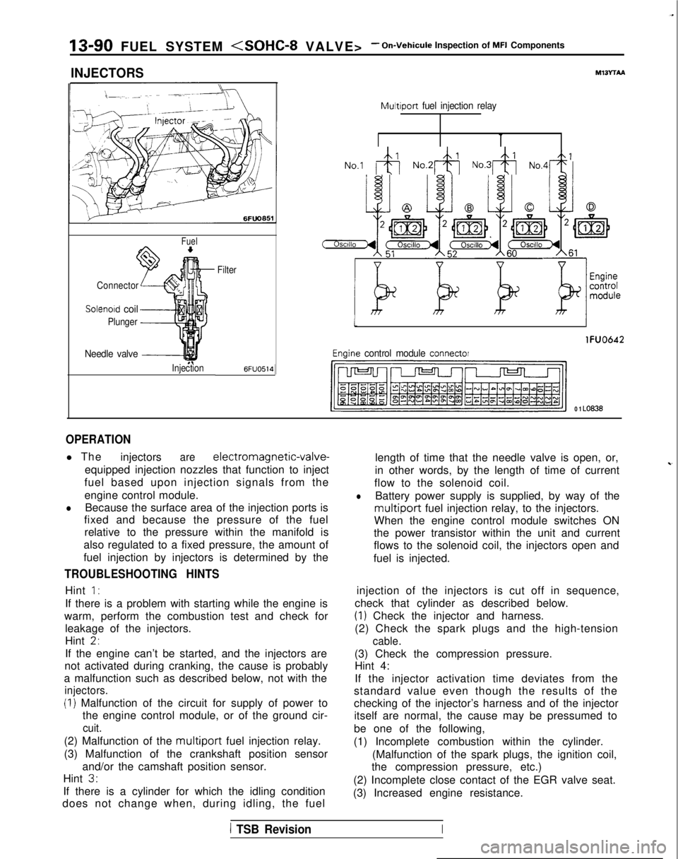
INJECTORS
Fuel
Connector
Solenoid coil
Plunger
Needle valve -----I
InjectionFilter6FUO514
M13rrAA
Multiport
fuel injection relay
No.1 &j No.2& No.3& No,4+
tI
lFUO642
Engine control module connector
CJ=JW=U-I
0 1 LO636
OPERATION
l The
injectorsare electromagnetic-valve-
equipped injection nozzles that function to inject
fuel based upon injection signals from the
engine control module.
lBecause the surface area of the injection ports is
fixed and because the pressure of the fuel
relative to the pressure within the manifold is
also regulated to a fixed pressure, the amount of
fuel injection by injectors is determined by the
TROUBLESHOOTING HINTS
Hint 1:
If there is a problem with starting while the engine is
warm, perform the combustion test and check for leakage of the injectors.
Hint
2,
If the engine can’t be started, and the injectors are
not activated during cranking, the cause is probably
a malfunction such as described below, not with the
injectors.
(I) Malfunction of the circuit for supply of power to the engine control module, or of the ground cir-
cuit.
(2) Malfunction of the multiport fuel injection relay.
(3) Malfunction of the crankshaft position sensor and/or the camshaft position sensor.
Hint
3.
If there is a cylinder for which the idling condition
does not change when, during idling, the fuel length of time that the needle valve is open, or,
in other words, by the length of time of current
~-
flow to the solenoid coil.
lBattery power supply is supplied, by way of the
multiport fuel injection relay, to the injectors.
When the engine control module switches ON
the power transistor within the unit and current
flows to the solenoid coil, the injectors open and
fuel is injected.
injection of the injectors is cut off in sequence,
check that cylinder as described below.
(1) Check the injector and harness.
(2) Check the spark plugs and the high-tension
cable.
(3) Check the compression pressure. Hint 4:
If the injector activation time deviates from the
standard value even though the results of the
checking of the injector’s harness and of the injector itself are normal, the cause may be pressumed to
be one of the following,
(1) Incomplete combustion within the cylinder. (Malfunction of the spark plugs, the ignition coil,
the compression pressure, etc.)
(2) Incomplete close contact of the EGR valve seat.
(3) Increased engine resistance.
1 TSB RevisionI