relay MITSUBISHI GALANT 1989 Service Repair Manual
[x] Cancel search | Manufacturer: MITSUBISHI, Model Year: 1989, Model line: GALANT, Model: MITSUBISHI GALANT 1989Pages: 1273, PDF Size: 37.62 MB
Page 9 of 1273
GENERAL - How to Use This Manual00-7
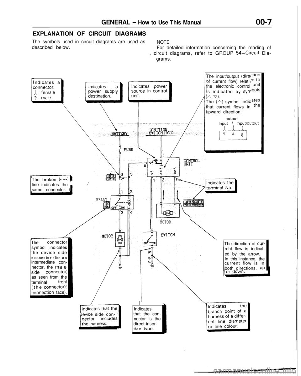
EXPLANATION OF CIRCUIT DIAGRAMS
The symbols used in circuit diagrams are used as
NOTE
described below. For detailed information concerning the reading of
, circuit diagrams, refer to GROUP
54lCircuit Dia-
grams.
Indicates
a
I
The input/output (direr
of current flow) relativ
the electronic control
is indicated by sym
(A.V).The (A) symbol
indic
that current flows in
upward direction.
output
The broken
(-.
line indicates the t
-
/r
same connector.
The connector
symbol indicates
the device side
connector (for an
intermediate con- nector, the male
side connectorj
as seen from the
terminal fronl
(the
connectois
rnnnection face).
RELAY
devce side con-
I
MOTOR
\
\
Indicates
that the con- nector is the
direct-inser-
tion tvoe.The direction of
cu.r-
reht flow is indicat-
ed by the arrow.
In this instance, the
current flow is in
both directions.
UP
Page 143 of 1273
13-1
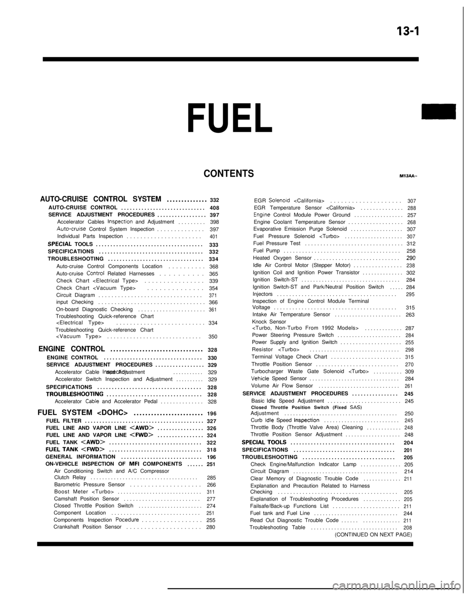
FUEL
CONTENTSM’ISAA--
AUTO-CRUISE CONTROL SYSTEM.............
.
332
AUTO-CRUISE CONTROL ............................. 408
SERVICE ADJUSTMENT PROCEDURES .................397
Accelerator Cables
inspectron and Adjustment ........
.
398 Auto-cruise
Control System Inspection
..............397
Individual Parts Inspection ......................
401SPECfAL
TOOLS
.....................................
333
SPECIFICATIONS .................................... 332
TROUBLESHOOTING ................................. 334
Auto-cruise Control Components Location ..........368
Auto-cruise Control
Related Harnesses
..........365
Check Chart
Check Chart
Circuit Diagram ................................
371input Checking................................
.
366
On-board Diagnostic Checking ......................
361Troubleshooting Quick-reference Chart
.
334
Troubleshooting Quick-reference Chart
ENGINE CONTROL...............................
.
328
ENGINE CONTROL ..................................
330
SERVICE ADJUSTMENT PROCEDURES .................329
Accelerator Cable inspectron and Adjustment
...........329
Accelerator Switch Inspection and Adjustment ..........329
SPECIFICATIONS ....................................
328
TROUBLESHOOTlNG................................
.
328
Accelerator
Cable and Accelerator Pedal .............
.
328
FUEL SYSTEM
FUEL FILTER .........................................
327
FUEL LINE AND VAPOR LINE
.
326
FUEL LINE AND VAPOR LINE
.
324
FUEL TANK
.
322
FUELTANK
.
318
GENERAL INFORMATION ............................ 196
ON-VEHICLE INSPECTION OF MFI
COMPONENTS
......251
Air Conditioning Switch and A/C Compressor Clutch Relay .....................................
285
Barometric Pressure Sensor .................... 266
Boost Meter
311Camshaft Position Sensor ........................
.
277Closed Throttle Position Switch
.....................
.
274
Component Location .............................
251Components Inspection Pocedure
................. 255
Crankshaft Position Sensor ..................... 280EGR
Solenord
...................
.
307EGR Temperature Sensor
.............
.
288Engrne Control Module Power Ground
................
.
257
Engine Coolant Temperature Sensor ..................
268Evaporative Emission Purge Solenoid .................
.
307
Fuel Pressure Solenoid
307Fuel Pressure Test...............................
.
312
Fuel Pump ...................................... 258
Heated Oxygen Sensor ............................ 290
Idle Air Control Motor (Stepper Motor) ................
238Ignition Coil and Ignition Power Transistor .............
.
302
Ignition Switch-ST .................................. 284
Ignition Switch-ST and Park/Neutral Position Switch .....284
Injectors .......................................
295Inspection of Engine Control Module Terminal
Voltage .......................................
.
315
Intake Air Temperature Sensor .......................263
Knock Sensor
Power Steering Pressure Switch ......................
284Power Supply and Ignition Switch ...................
.
255Resistor
..............................
.
298Terminal Voltage Check Chart
......................
.
315Throttle Position Sensor
..........................
.
270Turbocharger Waste Gate Solenoid
.........
.
309 Vehicle
Speed Sensor
............................... 284
Volume Air Flow Sensor ............................
261SERVICE ADJUSTMENT PROCEDURES ...............
.
245
Basic
idle Speed Adjustment .......................
.
245
Closed Throttle Position Switch (Fixed
SAS)Adjustment ......................................
.
250
Curb
Idle Speed Inspection
..........................245Throttle Body (Throttle Valve Area) Cleaning
...........
.
248Throttle Position Sensor Adjustment
..................
.
248
SPECIALTOOLS...................................
.
204
SPECIFICATIONS ...................................
201TROUBLESHOOTING ...............................
.
205
Check Engine/Malfunction Indicator Lamp ..............205
Circuit Diagram .................................... 214
Clear Memory of Diagnostic Trouble Code .............
211Explanation and Precaution Related to Harness
Checking ......................................
.
205Explanation of Troubleshooting Procedures
............
.
205Failsafe/Back-up Functions List
.....................
.
211Fuel tank and Fuel Line
............................
.
244
Read Out Diagnostic Trouble Code ...................
211Troubleshooting Table
.............................
.
208(CONTINUED ON NEXT PAGE)
Page 144 of 1273
13-2
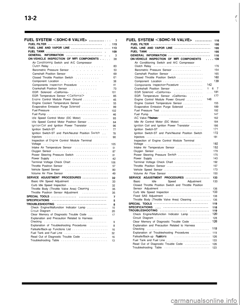
FUEL SYSTEM
..........
FUEL FILTER ....................................
FUEL LINE AND VAPOR LINE .....................FUELTANK....................................
.
GENERAL INFORMATION ........................
ON-VEHICLE INSPECTION OF MFI
COMPONENTS . .
Air
Conditionrng Switch and A/C CompressorClutch Relay ......
.
.............
Barometric Pressure Sensor .........
Camshaft Position Sensor ...........
Closed Throttle Position Switch ...........
Component Location .............
Components
Inspectron Procedure .......
.
Crankshaft Positron Sensor ............
EGR Solenoid
. . .3. .
115..,.113
. 109
. . 3
. . . 38
83
536961384173101EGR Temperature Sensor
.
85
Enqine Control Module Power Ground ......
.
....
45
Engine Coolant Temperature Sensor ...............
55Evaporative Emission Purge Solenord..............
.
99
Fuel Pressure ...............................
102Fuel Pump
...................................
.
46
Idle Speed Control Motor (DC Motor) ................
.
93
Idle Speed Control Motor Positron Sensor ............
.
64
lgnitron Co11 and Ignition Power Transistor .........
.
96
Ignition Switch-ST ..........................
77Ignition Switch-ST and Park/Neutral Position Switch
...78
Injectors..................................
.
90
Inspection of
Engrne Control Module Terminal
Voltage .........
.
..........................
105Intake Air Temperature Sensor ..................
.
51Oxygen Sensor
............................
.
87Power Steering Pressure Switch
..................
.
81Power Supply
.........................
.
42
Terminal Voltage Check Chart ......................
106Throttle Positron Sensor.....................
.
57Vehicle Speed Sensor
.........................
.
80
Volume Air Flow Sensor .........................
49
SERVICE ADJUSTMENT PROCEDURES .................
32
Basic
Idle Speed Adjustment ...................
.
33
Curb Idle Speed Inspection ..........................
32Throttle Body (Throttle Valve Area) Cleaning........
.
35
Throttle Positron Sensor Adjustment ................
35
SPECIAL TOOLS 7
.................
...................
SPECIFICATIONS ....................................
5
TROUBLESHOOTING .................................
8
Check Engine/Malfunction Indicator Lamp ..............
10Crrcuit Diagram.................................
.
20
Clear Memory of Diagnostic Trouble Code ............
17Explanation and Precaution Related to HarnessChecking......................................
.
9Explanation of Troubleshooting Procedures
...........
.
8
Failsafe/Back-up Functions List ....................
16Fuel Tank and Fuel Lrne.........................
.
32Read Out of Diagnostic Trouble Code
...............
.
16Troubleshooting Table
.........................
.
13
FUEL SYSTEM
116
FUEL FILTER .......................................
195
FUEL LINE AND VAPOR LINE ........................
195
FUEL TANK ........................................ 195
GENERAL INFORMATION ............................
116
ON-VEHICLE INSPECTION OF MFI
COMPONENTS
Air Conditioning Switch and A/C Compressor Clutch Relay .............................
Barometric Pressure Sensor .................
Camshaft Position Sensor ....................
Closed Throttle Position Switch ................
Component Location .......................
Components Inspectron Pocedure
..............
Crankshaft Position Sensor .................
EGR Solenoid
EGR Temperature Sensor
Engine Control Module Power Ground ..........
Engine Coolant Temperature Sensor .............
Evaporative Emission Purge Solenoid ............
Fuel Pressure Test ...........................
Fuel Pump ..................................
IAC Valve Positon Sensor
......................
Idle Air Control Motor (DC Motor) ..............
lgnrtion Coil and Ignition Power Transistor
.......
.
Ignition Switch-ST ...........................
Ignition Switch-ST and Park/Neutral Position Switch
Injectors ....................................
Inspection of Engine Control Module Terminal
Voltage .....................................
Intake Air Temperature Sensor .................
Oxygen Sensor .............................
Power Steering Pressure
Swatch..............
.
Power Supply ...............................
Terminal Voltage Check Chart ..................
Throttle Position Sensor .......................
Vehicle Speed Sensor ......................... . . . . 139
176
154
165
16013914216
7
..,_ 191177146
155
189192
147
162
184
186
171172181
192152
179
175
143
192
157
173
Volume Air Flow Sensor ...........................
.
150
SERVICE ADJUSTMENT PROCEDURES
...............
.
133
Basic Idle Speed Adjustment 133
Closed Throttle Position Switch and Throttle Position
Sensor Adjustment .................................
136Curb Idle Speed Inspection
.........................
.
133Fixed SAS Adjustment
.............................
.
138Throttle Body (Throttle Valve Area) Cleaning
...........
.
136
SPECIAL TOOLS
...................................
.
119
SPECIFICATIONS 118
.... ..............................
TROUBLESHOOTING ..................
.............
119
Check Engine/Malfunction Indicator Lamp ..............
120Circuit Diagram...................................
.
128Clear Memory of Diagnostic Trouble Code
............
.
126Explanation and Precaution Related to Harness
Checking ........................................
.
119Explanation of Troubleshooting Procedures
............
.
119Failsafe/Back-up
Fuctions List
........................
126
Fuel Tank and Fuel Line .............................
133Read Out of Diagnostic Trouble Code ................
.
126
Troubleshooting Table ..............................
123
Page 145 of 1273
FUEL SYSTEM
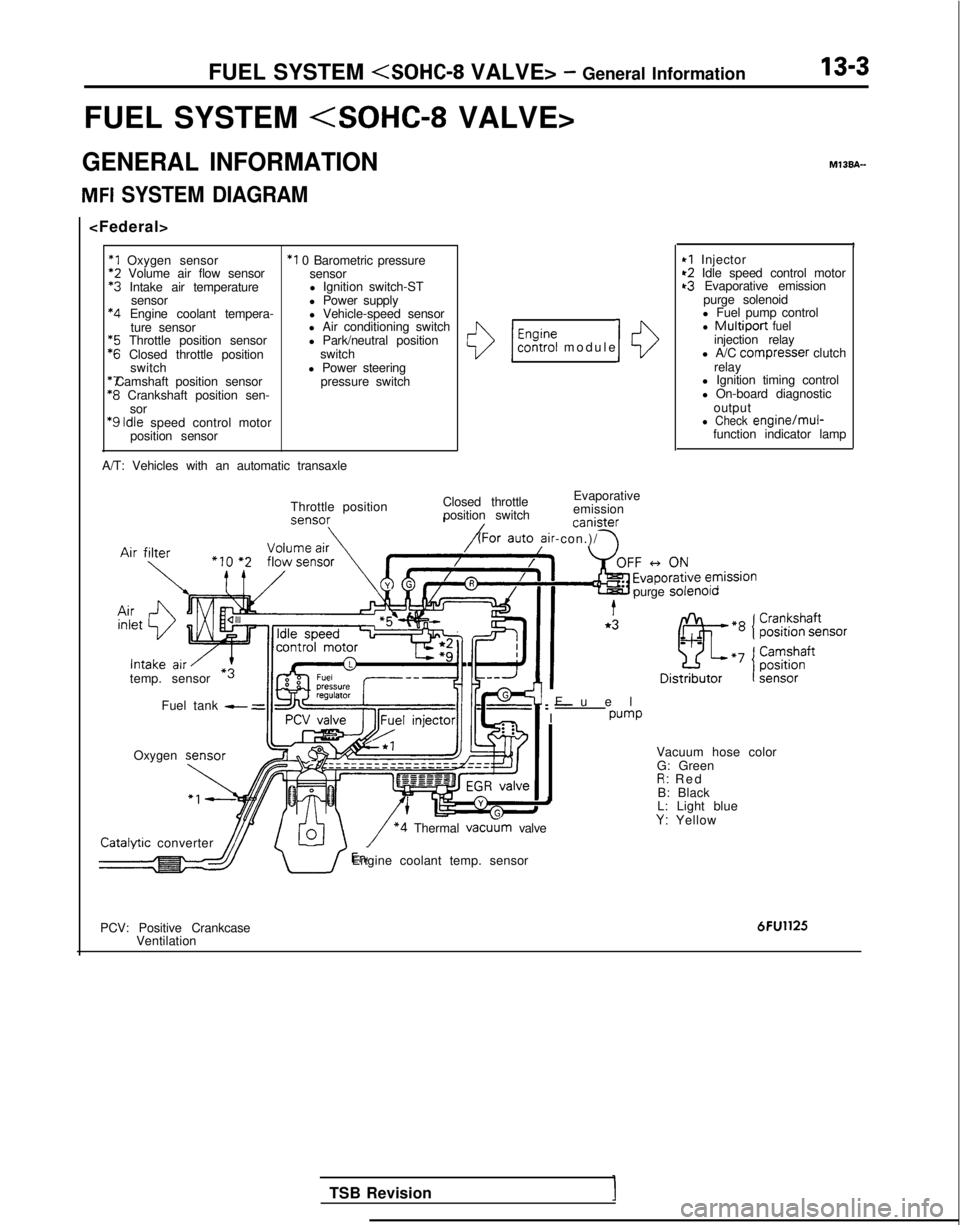
FUEL SYSTEM
GENERAL INFORMATION
MFI SYSTEM DIAGRAM
*1 Oxygen sensor
*2
Volume air flow sensor *3
Intake air temperature
sensor *4
Engine coolant tempera-
ture sensor *5
Throttle position sensor *6
Closed throttle position
switch *7 Camshaft position sensor
*8
Crankshaft position sen-
sor
‘9 Idle
speed control motor
position sensor
*I 0 Barometric pressure sensor
l Ignition switch-ST
l Power supply
l Vehicle-speed sensor
l Air conditioning switch
l Park/neutral position
switch
l Power steering pressure switch
A/T: Vehicles with an automatic transaxle
()/ $%?i modul
e
Closed throttle Evaporative
position switch emission canister
ir-con.)/ \
10
Throttle position
temp. sensor Fuel tank
- =
Oxygen M13BA-
I
*I Injector~2 Idle speed control motort3 Evaporative emission
purge solenoid
l Fuel pump control
l Multiport fuelinjection relay
l A/C compresser clutch
relay
l Ignition timing control
l On-board diagnostic
output
l Check engine/mul-function indicator lamp
Fue
l
: -
I
pump
purge
solenolo Catalvtic
converter
\/ *4 Thermal vacu
G: Green
R: Re
d
B: Black
L: Light blue
Y: Yellow
dJJ/ U’Engine coolant temp. sensor
PCV: Positive Crankcase Ventilation
6FU1125
TSB Revision
Page 146 of 1273
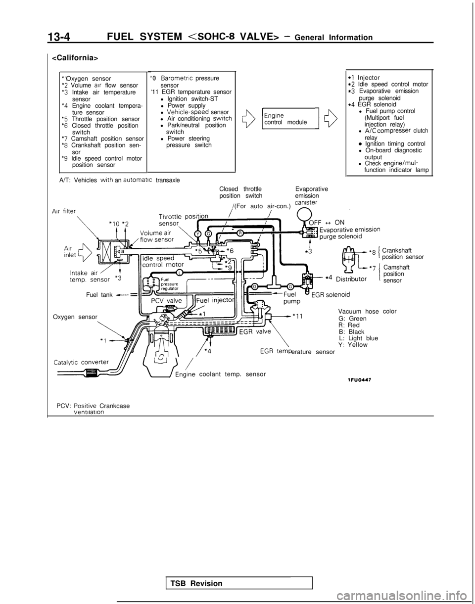
13-4FUEL SYSTEM
*2 Volume
air
flow sensor$3 Intake air temperature
sensor
*4 Engine coolant tempera-ture sensor
“5 Throttle position sensor‘6 Closed throttle position switch
*7 Camshaft position sensor*8 Crankshaft position sen-
sor
*9 Idle speed control motor position sensor “I 0
Barometric pressure
sensor
‘11 EGR temperature sensor
l Ignition switch-STl Power supply
l
Vehrcle-speed sensor
l Air conditioning switch
l Park/neutral position
switch
l Power steering pressure switchI13
Engrnecontrol module10
rl Injectort2 Idle speed control motorr3 Evaporative emission
purge solenoid
r4 EGR solenoidl Fuel pump control
(Multiport fuel
injection relay)
l A/C compresser clutchrelay0 Ignition timing control
l On-board diagnostic
output
l Check engine/muj-function indicator lamp
A/T: Vehicles
with an automatrc
transaxle
Closed throttleposition switch Evaporative
emission
/(For auto air-con.) can’ster
/ n
Vacuum hose
G: Green
R: Red
B: Black L: Light blue
Y: Yellow
erature sensor Air
filter
Fuel tank - =
Oxygen sensor
\ U /Eni coolant temp. sensor1FUO447
Crankshaft
position sensor
Camshaft
position
sensor
color
PCV: Posrtive
Crankcase
TSB Revision
Page 147 of 1273
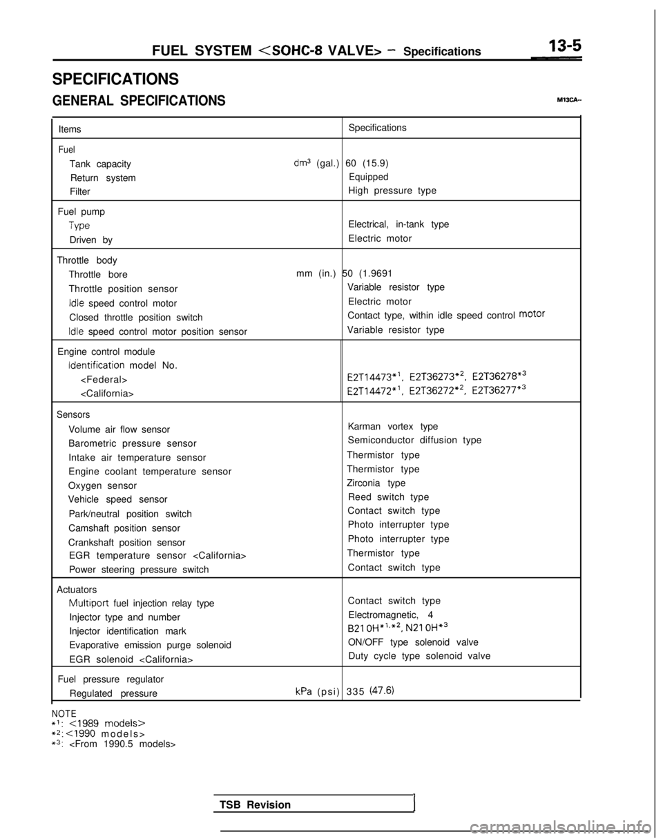
FUEL SYSTEM
SPECIFICATIONS
GENERAL SPECIFICATIONS
Items
Fuel
Tank capacity
Return system
Filter
Fuel pump
Type
Driven by
Throttle body Throttle bore
Throttle position sensor
Idle speed control motor
Closed throttle position switch
Idle speed control motor position sensor
Engine control module Identification
model No.
Sensors
Volume air flow sensor
Barometric pressure sensor
Intake air temperature sensor
Engine coolant temperature sensor
Oxygen sensor
Vehicle speed sensor
Park/neutral position switch
Camshaft position sensor
Crankshaft position sensor EGR temperature sensor
Power steering pressure switch
Actuators
Multiport fuel injection relay type
Injector type and number
Injector identification mark
Evaporative emission purge solenoid
EGR solenoid
Fuel pressure regulator Regulated pressure
NOTE*I:
*3:
dm3 (gal.) 60 (15.9)
Equipped
High pressure type
Electrical, in-tank type
Electric motor
mm (in.) 50 (1.9691 Variable resistor type
Electric motor
Contact type, within idle speed control motor
Variable resistor type E2T14473*‘,
E2T36273*2, E2T36278*3
E2T14472”. E2T36272*2, E2T36277*3
Karman vortex type
Semiconductor diffusion type
Thermistor type
Thermistor type
Zirconia type Reed switch type
Contact switch type
Photo interrupter type
Photo interrupter type
Thermistor type
Contact switch type
Contact switch typeElectromagnetic, 4
B21 OH*‘,*2,
N21 OH*3
ON/OFF type solenoid valve
Duty cycle type solenoid valve
kPa (psi) 335 (47.6)
TSB RevisionI
Page 154 of 1273
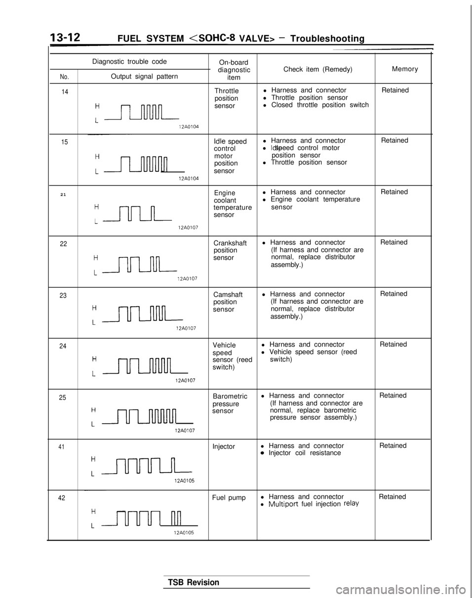
13-12
FUEL SYSTEM
No.
14
Diagnostic trouble code
On-board
diagnostic Check item (Remedy)
Memory
Output signal pattern item
Throttle l Harness and connector
Retained
position l Throttle position sensor
:-
sensor l Closed throttle position switch 12A0104
15
Idle
speed l Harness and connector
Retained
control l Idle speed control motor
n
motor
position sensor
position l Throttle position sensor
sensor 12A0104
21
Enginel Harness and connector Retained
coolant l Engine coolant temperature
“=
temperature
sensor
sensor 12A0107
22Crankshaft
l Harness and connector
Retained
position (If harness and connector are
:-
sensor normal, replace distributor
assembly.) 12A0107
23Camshaft
l Harness and connector
Retained
position (If harness and connector are
:=
sensor normal, replace distributor
assembly.) 12A0107
24Vehicle
l Harness and connector
Retained
speed l Vehicle speed sensor (reed
H
uulnnn
sensor (reed
switch)
switch)
L 12A0107
25Barometric
l Harness and connector
Retained
pressure (If harness and connector are
H
ULnMnn
sensor
normal, replace barometric
pressure sensor assembly.)
L 12A0107
41Injector
l Harness and connector
Retained0 Injector coil resistance
:a 12A0105
42Fuel pump
l Harness and connector
Retained
l Multiport fuel injection relay
Luuul nn
12A0105
TSB Revision
Page 157 of 1273
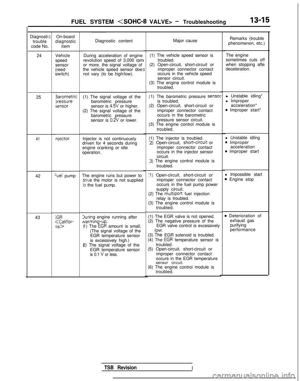
FUEL SYSTEM
Diagnosti
trouble
code No.
24
25
41
42Set pump
43
iGR;aC;lifor-
COn-board
diagnostic
item
Vehicle
speed
sensor
(reed
switch) 3arometric
Iressuresensor
njector
Diagnostic content
Major cause
During acceleration of engine
revolution speed of 3,000 rpm
or more, the signal voltage of
the vehicle speed sensor doe: not vary (to be high/low). (1) The vehicle speed sensor is
troubled.
(2) Open-circuit, short-circuit or
improper connector contact
occurs in the vehicle speed
sensor circuit.
(1) The signal voltage of the barometric pressure
sensor is 4.5V or higher.
(2) The signal voltage of the barometric pressure
sensor is
0.2V or lower.
Injector is not continuously
driven for 4 seconds during
engine cranking or idle
operation.
The engine runs but power to
irive the motor is not supplied
:o the fuel pump.
luring engine running after Narming-up,
1) The
EGR amount is small.
(The signal voltage of the EGR temperature sensor
is excessively high.)
2) The signal voltage of the
EGR temperature sensor
is 0.1 V or less.
(3) The engine control module is troubled.
1) The barometric pressure sense
is troubled.
2) Open-circuit, short-circuit or
improper connector contact
occurs in the barometric pressure sensor circuit.
‘3) The engine control module is
troubled.
‘1) The injector is troubled.
12) Open-circuit, short-crrcuit
or
improper connector contact
occurs in the injector sensor
circuit.
13) The engine control module is
troubled.
:I) Open-circuit, short-circuit or improper connector contact
occurs in the fuel pump power
supply circuit.
(2) The
multiport fuel injection
relay is troubled.
(3) The engine control module is
troubled.
(1) The EGR valve is not opened.
(2) The negative pressure of the EGR valve control is excessively
(3)
?h”e EGR solenoid is troubled.
(4) The EGR temperature sensor is
troubled.
(5) Open-circuit, short-circuit or
improper connector contact
occurs in the EGR temperature
sensor circuit.
(6) The engine control module is troubled.
r 1l Unstable idling*
l Improper acceleration*
0 Improper start*
l Unstable idling
0 Improper acceleration
0 Improper start
l Impossible start
3 Engine stop4
4
,
B Deterioration of exhaust gaspurifying
performance
Remarks (trouble
phenomenon, etc.)
The engine
sometimes cuts off
when stopping afte
deceleration.
TSB RevisionI
Page 162 of 1273
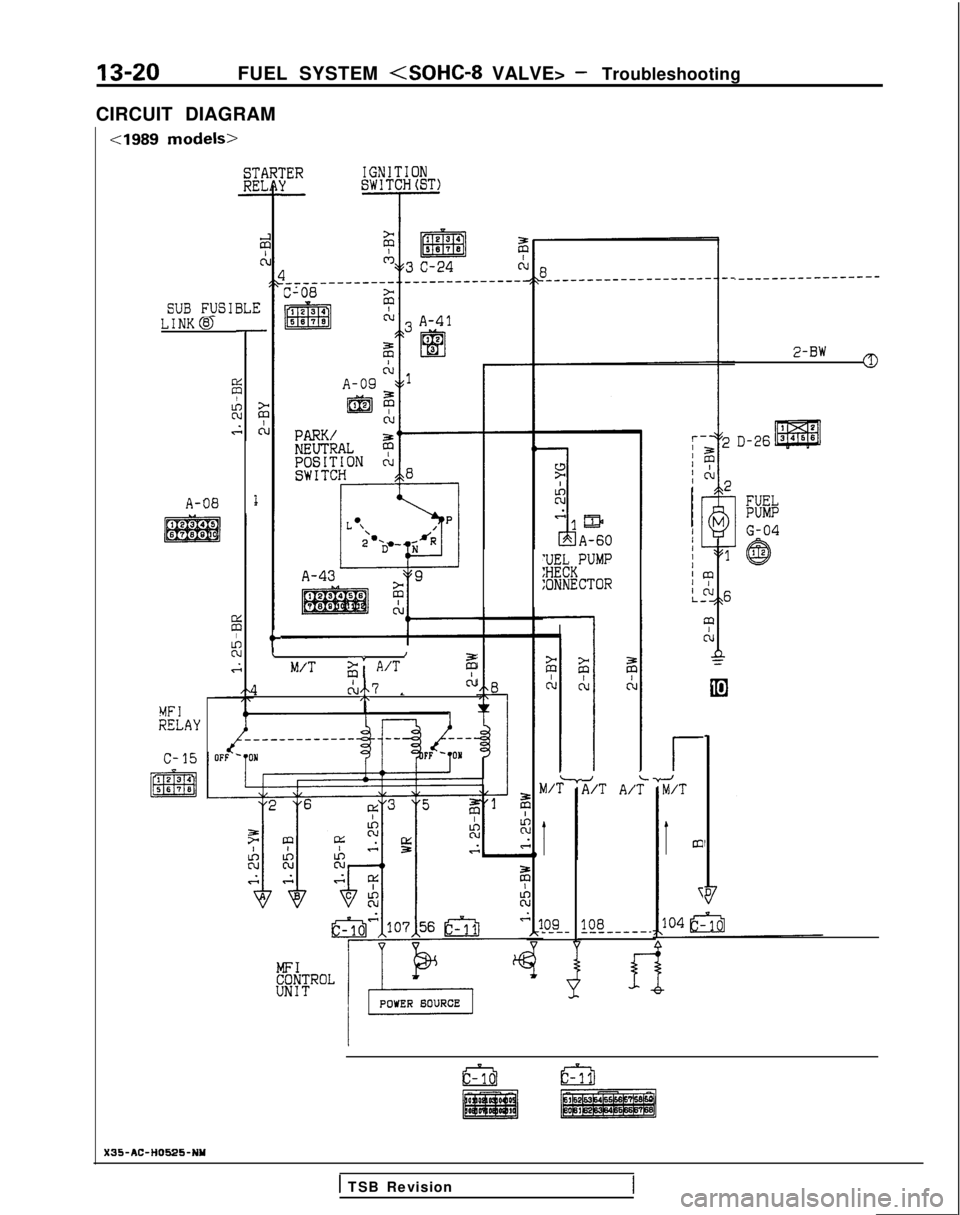
13-20FUEL SYSTEM
CIRCUIT DIAGRAM
cl989 models>
iERIGNITIONSWITCHbST)-
SUB F_USIBLE
.-__-____----w-w--
2-BW0
LINK@
A-08
;;IJkKPUMP
:ONNECTOR
t\I
M/Tg' A/Tz
1ch7 LCL/.MFIRELAY
r
TuT;T
Im
\
Zi/T A/r;
09108_------------
X35-AC-H0525-NY
1 TSB Revision
Page 164 of 1273
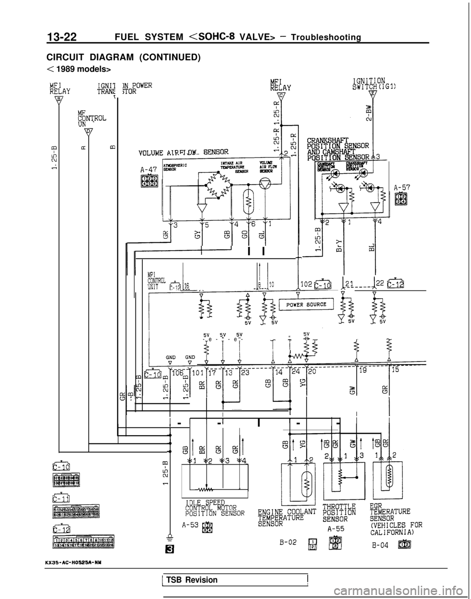
13-22
FUEL SYSTEM
CIRCUIT DIAGRAM (CONTINUED)
< 1989 models>
IGNITIONSWITCHlIGl)#OF?OWERMFIRELAYIGNIlTRANf
;ROLKUN1
am\lR Fl.tlW i=XNSOR
A-57
II Il-
EF g?JEi _______ JLllOI:02&j12_1---& im
Y-+-I
k$$
Yh
I5VI I 5Y
syv s_v-e-*-e
-
“,
*-r
-5. IIII 5.5
c
L
III I
III1II --I-
-
I
II,---
1’ 8Iis%%
Gi3mv1 a+2 pg3 $14I
?Ic
IDLE SPEEDCONTROL MOTORPOSITJON SENSOR
A-53 12El(VEHICLES FOR94CALIFORNIA)
B-02 B @
KX35-AC-HO525A-NY
B-04 m
1 TSB Revision1I