spark plugs replace MITSUBISHI GALANT 1989 Service Repair Manual
[x] Cancel search | Manufacturer: MITSUBISHI, Model Year: 1989, Model line: GALANT, Model: MITSUBISHI GALANT 1989Pages: 1273, PDF Size: 37.62 MB
Page 40 of 1273
00-38GENERAL- Scheduled Maintenance Table
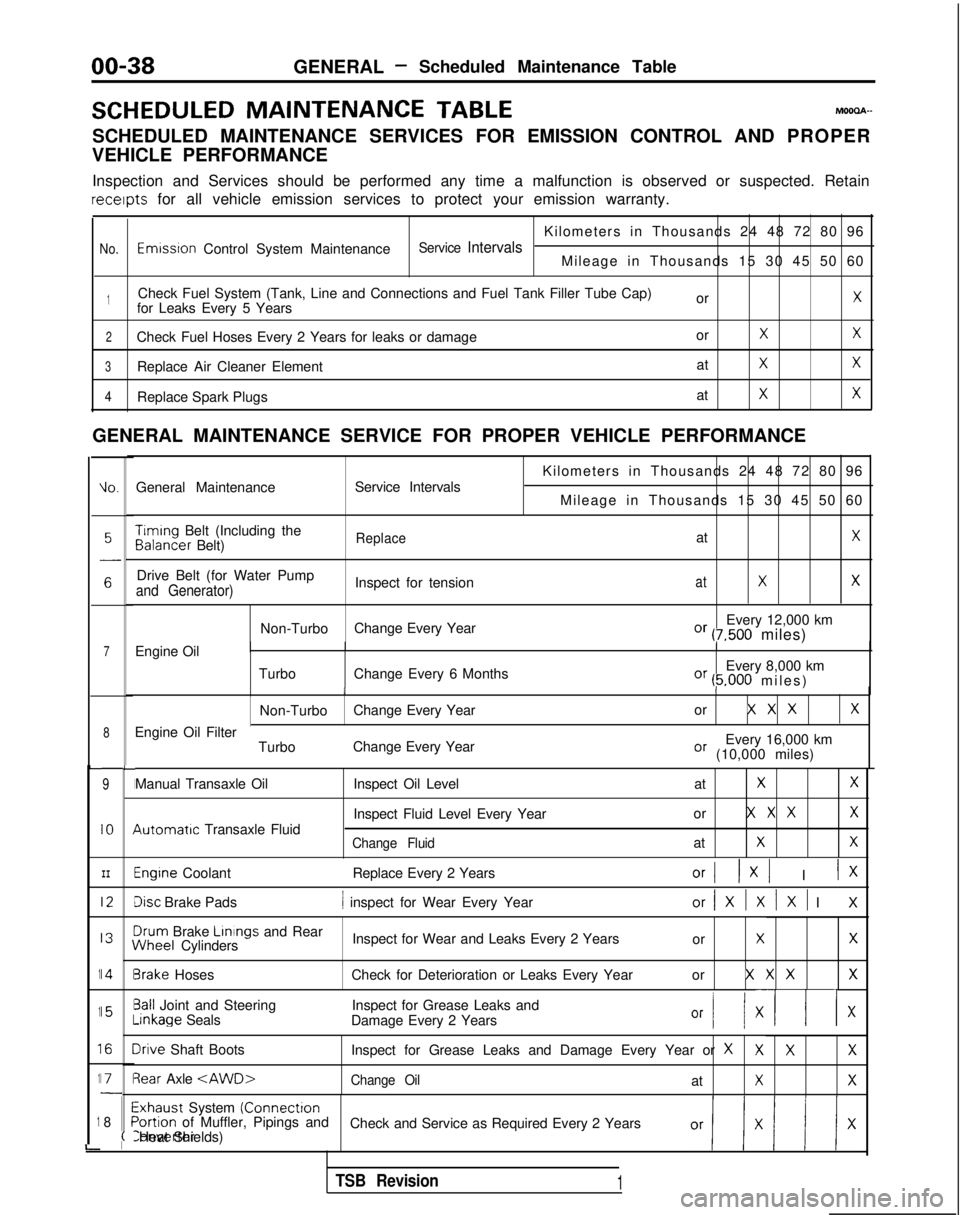
SCHEDULED MAINTENANCE
TABLEMOOOA-
SCHEDULED MAINTENANCE SERVICES FOR EMISSION CONTROL AND PROPER
VEHICLE PERFORMANCE
Inspection and Services should be performed any time a malfunction is ob\
served or suspected. Retain receipts
for all vehicle emission services to protect your emission warranty.
Kilometers in Thousands 24 48 72 80 96
No.Emwsron Control System MaintenanceService IntervalsMileage in Thousands 15 30 45 50 60
1Check Fuel System (Tank, Line and Connections and Fuel Tank Filler Tube\
Cap) orXfor Leaks Every 5 Years
2Check Fuel Hoses Every 2 Years for leaks or damage orXX
3Replace Air Cleaner ElementatXX
4Replace Spark PlugsatXX
GENERAL MAINTENANCE SERVICE FOR PROPER VEHICLE PERFORMANCE
L
1
1
1
1
1
i
IO.General Maintenance
Service Intervals
7Engine Oil
8
9
IO
III2
I3
14
15
I6
I71
8
L
I
I
I
I
I\
I
II
I
I
;(
Kilometers in Thousands 24 48 72 80 96
Mileage in Thousands 15 30 45 50 60 Timing
Belt (Including the Balancer
Belt)
ReplaceatX
Drive Belt (for Water Pump
Inspect for tensionatXXand Generator)
Non-TurboChange Every Year Every 12,000 kmOr (7,500 miles)
Turbo Change Every 6 Months Every 8,000 km
Or (5.000 miles
)
II
Non-Turbo
Change Every Year or X X XX
Every 16,000 kmOr (10,000 miles)
Engine Oil Filter
TurboChange Every Year
Manual Transaxle Oil 4utomatrc
Transaxle Fluid Inspect Oil Level
at
XX
Inspect Fluid Level Every Yearor X X XX
Change FluidatXX
Engine Coolant
Replace Every 2 YearsOrI 1x1 I IX
Disc Brake Pads1 inspect for Wear Every Yearor/XlXlXl I
X
3rum
Brake Linings
and Rear iNheel
Cylinders Inspect for Wear and Leaks Every 2 Years
or
XX
3rake HosesCheck for Deterioration or Leaks Every Year or X X XX
3all Joint and SteeringInspect for Grease Leaks and-inkage
Seals
Damage Every 2 Years
Or I/ XII x
Irive Shaft Boots Inspect for Grease Leaks and Damage Every Year or XXXX
3ear Axle
Exhaust System (Connectron>ortion of Muffler, Pipings and
Check and Service as Required Every 2 YearsConverter Heat Shields)
TSB Revision1
Page 42 of 1273
00-40GENERAL- Maintenance Service
Caution
The air cleaner cover should be removed carefully,
because it includes the volume air flow sensor.
/
(5) Remove the air cleaner element.(6) Set a new air cleaner element and install the air cleaner cover.
I hose,I
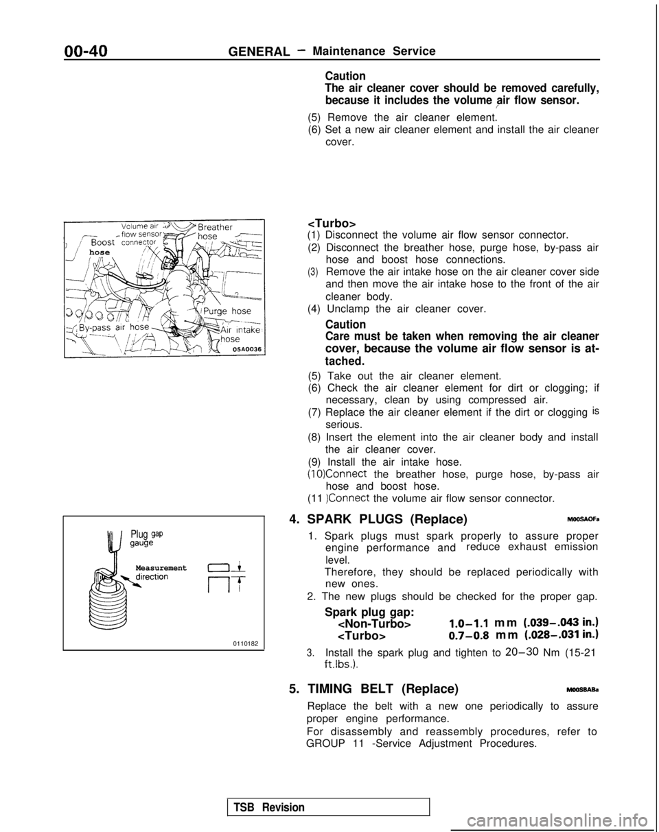
Plug gapgauge
Measurementrection01
If
0110182
(1) Disconnect the volume air flow sensor connector.
(2) Disconnect the breather hose, purge hose, by-pass air hose and boost hose connections.
(3)Remove the air intake hose on the air cleaner cover side
and then move the air intake hose to the front of the air
cleaner body.
(4) Unclamp the air cleaner cover.
Caution
Care must be taken when removing the air cleaner
cover, because the volume air flow sensor is at-
tached.
(5) Take out the air cleaner element.
(6) Check the air cleaner element for dirt or clogging; if necessary, clean by using compressed air.
(7) Replace the air cleaner element if the dirt or clogging
is
serious.
(8) Insert the element into the air cleaner body and install the air cleaner cover.
(9) Install the air intake hose.
(10)Connect the breather hose, purge hose, by-pass air
hose and boost hose.
(11
)Connect the volume air flow sensor connector.
4. SPARK PLUGS (Replace)
h%OSAOFa
1. Spark plugs must spark properly to assure proper engine performance and reduce exhaust emission
level.
Therefore, they should be replaced periodically with
new ones.
2. The new plugs should be checked for the proper gap.
Spark plug gap:
mm (.039-.043
in.)
0.7-0.8 mm (.028-.031 in.)
3.Install the spark plug and tighten to 20-30 Nm (15-21
ftlbs.).
5. TIMING BELT (Replace)moossAsa
Replace the belt with a new one periodically to assure
proper engine performance.
For disassembly and reassembly procedures, refer to
GROUP 11 -Service Adjustment Procedures.
TSB Revision
Page 58 of 1273
II-8ENGINE
8 VALVE
W Tlmlng belt side
il6
16
727
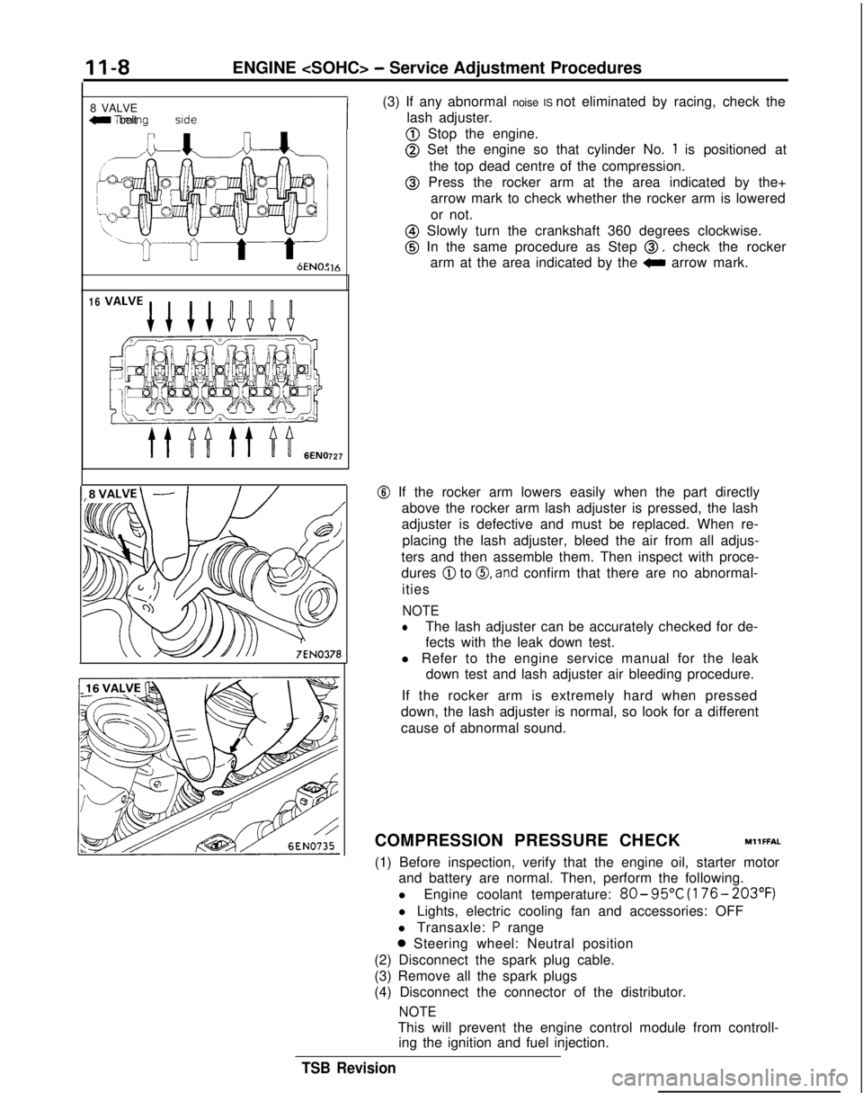
(3) If any abnormal noise IS not eliminated by racing, check the
lash adjuster.
@ Stop the engine.
@ Set the engine so that cylinder No. 1 is positioned at
the top dead centre of the compression.
@ Press the rocker arm at the area indicated by the+ arrow mark to check whether the rocker arm is lowered
or not.
@ Slowly turn the crankshaft 360 degrees clockwise.
@ In the same procedure as Step 0, check the rocker
arm at the area indicated by the
0 arrow mark.
@ If the rocker arm lowers easily when the part directly
above the rocker arm lash adjuster is pressed, the lash
adjuster is defective and must be replaced. When re-
placing the lash adjuster, bleed the air from all adjus-
ters and then assemble them. Then inspect with proce-
dures
@ to 0, and confirm that there are no abnormal-
ities
NOTE
lThe lash adjuster can be accurately checked for de-
fects with the leak down test.
l Refer to the engine service manual for the leak down test and lash adjuster air bleeding procedure.
If the rocker arm is extremely hard when pressed
down, the lash adjuster is normal, so look for a different
cause of abnormal sound.
COMPRESSION PRESSURE CHECK
MllFFAL
(1) Before inspection, verify that the engine oil, starter motor and battery are normal. Then, perform the following.
l Engine coolant temperature:
80- 95°C
(176- 203°F)
l Lights, electric cooling fan and accessories: OFF
l Transaxle:
P range
0 Steering wheel: Neutral position
(2) Disconnect the spark plug cable.
(3) Remove all the spark plugs
(4) Disconnect the connector of the distributor.
NOTE
This will prevent the engine control module from controll- ing the ignition and fuel injection.
TSB Revision
Page 60 of 1273
II-IOENGINE
(3) Remove the PCV hose from the PCV valve and attach a
vacuum gauge.
(4) Check that the negative pressure at the intake manifold
during idle revolution is normal.
Standard value:
(8 VALVE>Approx. 500 mmHg (20 in.Hg)
<16VALVE>Approx. 510 mmHg (20 in.Hg)
(5) If outside the standard value, isolate the cause by referring
to the following table and repair the fault.
Symptom
CauseRemed
y
l The vacuum gauge reading is less than l Ignition timing is retarded.l Adjust the ignition timing.
standard value, but the pointer is
stable.
l The vacuum gauge pointer swings l The gas mixture is excessivelyl Check
Multiport Fuel Injection
slowly.rich.system.
l The vacuum gauge pointer drops irre-
l The gas mixture is excessively
l Check
Multiport Fuel Injectiongularly.lean.system.
l The vacuum gauge pointer drops inter-
0 Incomplete close contact of in-0 Check and repair the valve.mittently to 30 to 160
mmHg
(1.2 to take and exhaust valve seats.
6.3 in.Hg).
l The vacuum gauge pointer drops sud-l Broken cylinder head gasketl ,Replace cylinder head gasket. denly
from the normal reading to 250 mmHg
(9.8 in.Hg). then returns to
normal.
/ OlR0175
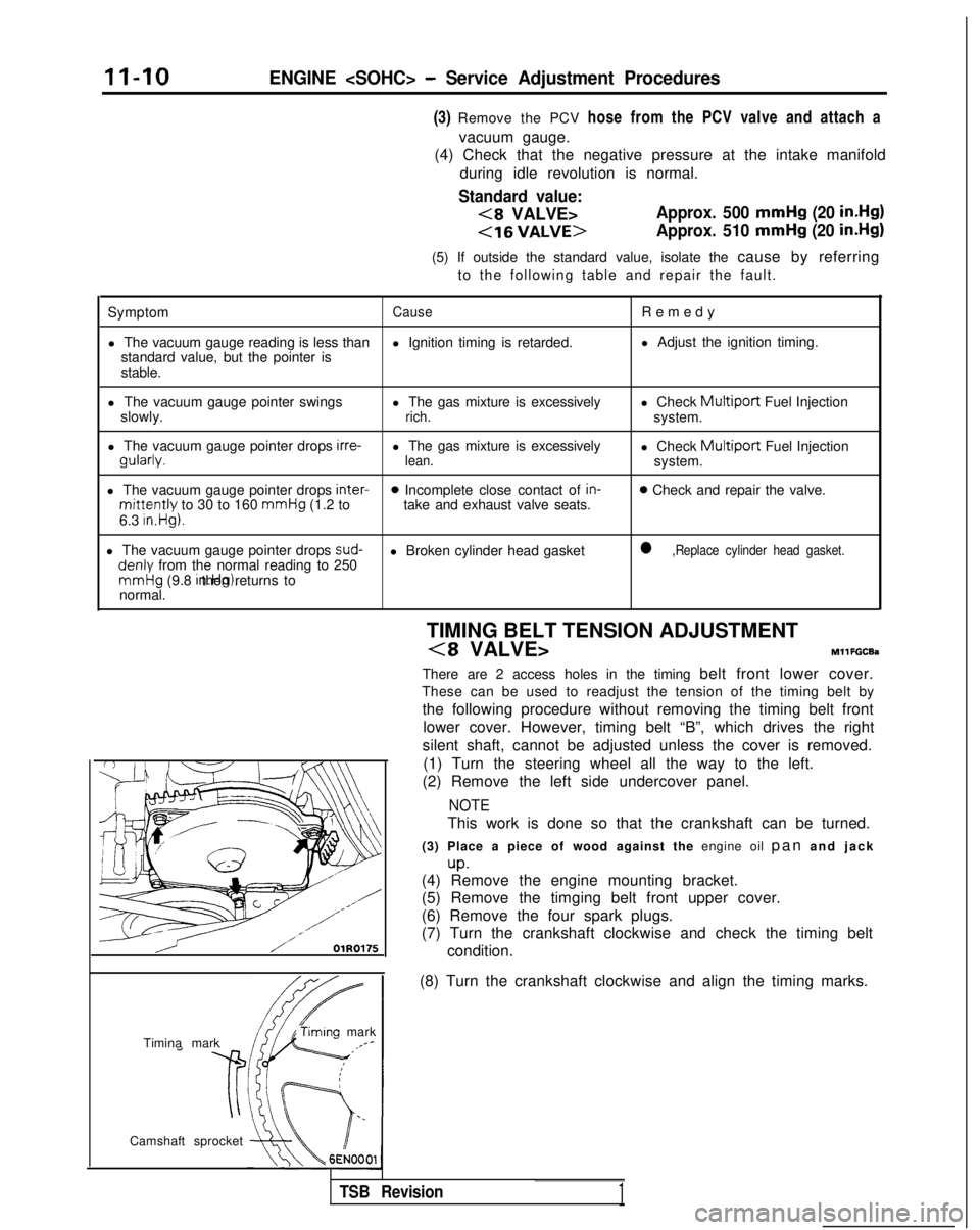
condition.
Timina mark
‘timing mark._*-
Camshaft sprocket TIMING BELT TENSION ADJUSTMENT
(8 VALVE>MllFGCEa
There are 2 access holes in the timing belt front lower cover.
These can be used to readjust the tension of the timing belt by
the following procedure without removing the timing belt front lower cover. However, timing belt “B”, which drives the right
silent shaft, cannot be adjusted unless the cover is removed. (1) Turn the steering wheel all the way to the left.
(2) Remove the left side undercover panel.
NOTE
This work is done so that the crankshaft can be turned.
(3) Place a piece of wood against the engine oil pan and jac
k
up.(4) Remove the engine mounting bracket.
(5) Remove the timging belt front upper cover.
(6) Remove the four spark plugs.
(7) Turn the crankshaft clockwise and check the timing belt
(8) Turn the crankshaft clockwise and align the timing marks.
TSB Revision1
Page 1268 of 1273
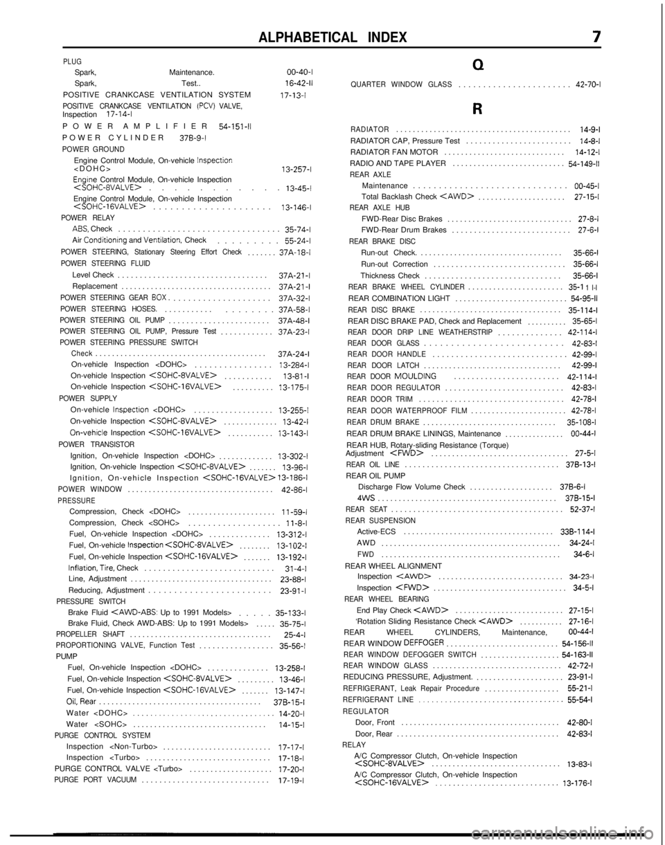
ALPHABETICAL INDEX
PLUGSpark, Maintenance. 00-40-I
Spark, Test..
16-42-11
POSITIVE CRANKCASE VENTILATION SYSTEM 17-13-l
POSITIVE CRANKCASE VENTILATION (PCV) VALVE,Inspection
17-14-I
POWER AMPLIFIER
54-151-11POWER CYLINDE
R
378-9-I
POWER GROUND
Engine Control Module, On-vehicle
Inspection
Engrne Control Module, On-vehicle Inspection
.
13-45-l
Engine Control Module, On-vehicle Inspection
.
13-146-I
POWER RELAY
ABS. Check
................................
.
35-74-l
Air
Conditionrng and Ventrlation. Check ........
.
55-24-l
POWER STEERING, Stationary Steering Effort Check......
.
37A-18-l
POWER STEERING FLUID
Level Check
.................................
.
37A-21-l
Replacement .................................... 37A-21-I
POWER STEERING GEAR 80X....................
.
37A-32-l
POWER STEERING HOSES...........
.
........ 37A-58-l
POWER STEERING OIL PUMP......................
.
37A-48-l
POWER STEERING OIL PUMP, Pressure Test...........
.
37A-23-l
POWER STEERING PRESSURE SWITCH
Check
........................................
.
37A-24-l
On-vehicle Inspection
On-vehicle Inspection
.
13-81 -IOn-vehicle Inspection
.
13-175-l
POWER SUPPLY
On-vehicle Inspectron
.................
.
13-255-l
On-vehicle Inspection
.
13-42-I
On-vehrcle Inspection
.
13-143-l
POWER TRANSISTOR
Ignition, On-vehicle Inspection
............
.
13-302-I
Ignition, On-vehicle Inspection
.
13-96-l
Ignition, On-vehicle Inspection
POWER WINDOW..................................
.
42-86-l
PRESSURECompression, Check
....................
.
11-59-i
Compression, Check
1 l-8-lFuel, On-vehicle Inspection
.
13-312-I
Fuel, On-vehicle Inspection
.
13-102-I
Fuel, On-vehicle Inspection
.
13-192-l
Inflation,Tire,
Check
............................ 31-4-I
Line, Adjustment .................................. 23-88-l
Reducing, Adjustment ........................
23-91 -IPRESSURE SWITCH
Brake Fluid
....
.
35-133-I
Brake Fluid, Check AWD-ABS: Up to 1991 Models> ..... 35-75-l
PROPELLER SHAFT.................................
.
25-4-l
PROPORTIONING VALVE, Function Test................
.
35-56-l
PUMP
Fuel, On-vehicle Inspection
Fuel, On-vehicle Inspection
.
13-46-l
Fuel, On-vehicle Inspection
.
13-147-l
OiLRear
....................................... 37B-15-l
Water
................................ 14-20-I
Water
14-I 5-1PURGE CONTROL SYSTEM
Inspection
.........................
.
17-17-I
Inspection
PURGE CONTROL VALVE
PURGE PORT VACUUM............................
.
17-19-I
Q
QUARTER WINDOW GLASS......................
.
42-70-I
R
RADIATOR.........................................
.
14-9-lRADIATOR CAP, Pressure Test
.......................
.
14-8-lRADIATOR FAN MOTOR
............................
.
14-12-lRADIO AND TAPE PLAYER
..........................
.
54-149-11REAR AXLE
Maintenance
.............................
.
00-45-I
Total Backlash Check
.
27-15-I
REAR AXLE HUB
FWD-Rear Disc Brakes
.............................
.
27-8-l
FWD-Rear Drum Brakes ........................... 27-6-l
REAR BRAKE DISC
Run-out Check.
.................................
.
35-66-l
Run-out Correction .............................. 35-66-l
Thickness Check ............................... 35-66-l
REAR BRAKE WHEEL CYLINDER......................
.
35-l 1 l-lREAR COMBINATION LIGHT
..........................
.
54-95-IREAR DISC BRAKE.................................
.
35-l 14-lREAR DISC BRAKE PAD, Check and Replacement
.........
. 35-65-l
REAR DOOR DRIP LINE WEATHERSTRIP.............
.
42-l 14-lREAR DOOR GLASS.........................
.
42-83-l
REAR DOOR HANDLE............................
.
42-99-l
REAR DOOR LATCH................................
.
42-99-l
REAR DOOR
MOULDING
........................42-l 14-l
REAR DOOR REGULATOR..........................
.
42-83-l
REAR DOOR TRIM................................
.
42-78-l
REAR DOOR WATERPROOF FILM......................
.
42-78-l
REAR DRUM BRAKE...............................
.
35-108-I
REAR DRUM BRAKE LININGS, Maintenance ............... 00-44-I
REAR HUB, Rotary-sliding Resistance (Torque)
Adjustment
.
27-5-l
REAR OIL LINE..................................
.
378-13-I
REAR OIL PUMP
Discharge Flow Volume Check .................... 378-6-I
4WS
........................................... 378-15-I
REAR SEAT......................................
.
52-37-l
REAR SUSPENSION
Active-ECS
...................................
.
338-l 14-lAWD
..........................................
.
34-24-l
FWD..........................................
.
34-6-l
REAR WHEEL ALIGNMENT Inspection
.
34-23-l
Inspection
.
34-5-l
REAR WHEEL BEARING
End Play Check
.
27-15-I
‘Rotation Sliding Resistance Check
.
27-16-I
REAR WHEEL CYLINDERS, Maintenance, 00-44-I
REAR WINDOW
DEFFOGER..........................
.
54-156-11REAR WINDOW DEFOGGER SWITCH..................
.
54-163-11REAR WINDOW GLASS..............................
.
42-72-l
REDUCING PRESSURE, Adjustment. ..................... 23-91-l
REFRIGERANT, Leak Repair Procedure.................
.
55-21-l
REFRIGERANT LINE..................................
55-54-l
REGULATOR
Door, Front
.....................................
.
42-80-I
Door, Rear ....................................... 42-83-l
RELAY
A/C Compressor Clutch, On-vehicle Inspection
.
13-83-lA/C Compressor Clutch, On-vehicle Inspection
13-176-I