warning lights MITSUBISHI GALANT 1989 Service Repair Manual
[x] Cancel search | Manufacturer: MITSUBISHI, Model Year: 1989, Model line: GALANT, Model: MITSUBISHI GALANT 1989Pages: 1273, PDF Size: 37.62 MB
Page 1140 of 1273
SERVICE BRAKES - Anti-lock Braking System Troubleshooting35-19
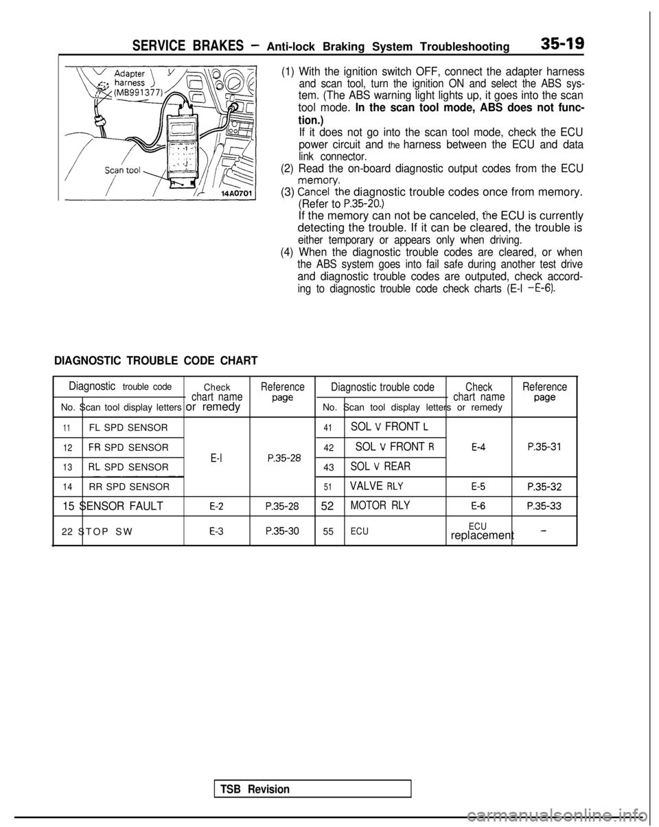
(1) With the ignition switch OFF, connect the adapter harness
and scan tool, turn the ignition ON and select the ABS sys-
tem. (The ABS warning light lights up, it goes into the scan
tool mode.
In the scan tool mode, ABS does not func-
tion.)
If it does not go into the scan tool mode, check the ECU
power circuit and
the harness between the ECU and data
link connector.
(2) Read the on-board diagnostic output codes from the ECU
(3) ?a\?zl’ythe diagnostic trouble codes once from memory.
(Refer to P.35-20.)
If the memory can not be canceled, the ECU is currently
detecting the trouble. If it can be cleared, the trouble is
either temporary or appears only when driving.
(4) When the diagnostic trouble codes are cleared, or when
the ABS system goes into fail safe during another test drive
and diagnostic trouble codes are outputed, check accord-
ing to diagnostic trouble code check charts (E-l -E-6).
DIAGNOSTIC TROUBLE CODE CHART
Diagnostic trouble code CheckReferenceDiagnostic trouble codeCheckReference
chart name
pawchart namepawNo. Scan tool display letters or remedy No. Scan tool display letters or remedy
11FL SPD SENSOR41SOL V FRONT L
12FR SPD SENSOR42SOL V FRONT RE-4P.35-31
E-lP.35-2813RL SPD SENSOR
43SOL V REAR
14RR SPD SENSOR51VALVE RLYE-5P.35-32
15 SENSOR FAULTE-2P.35-28 52MOTOR RLYE-6P.35-33
22 STOP SWE-3P.35-30 55ECU ECUreplacement -
TSB Revision
Page 1142 of 1273
![MITSUBISHI GALANT 1989 Service Repair Manual SERVICE BRAKES - Anti-lock Braking System Troubleshooting35-21
A ABS warning light does not light at all.
[Explanation]
When it does not light up at all, there is a strong
possibility that there is tr MITSUBISHI GALANT 1989 Service Repair Manual SERVICE BRAKES - Anti-lock Braking System Troubleshooting35-21
A ABS warning light does not light at all.
[Explanation]
When it does not light up at all, there is a strong
possibility that there is tr](/img/19/57312/w960_57312-1141.png)
SERVICE BRAKES - Anti-lock Braking System Troubleshooting35-21
A ABS warning light does not light at all.
[Explanation]
When it does not light up at all, there is a strong
possibility that there is trouble with ABS warning
light or with power to the light.
[Hint]
If other warning lights do not light up either, fuse is
probably blown.
MAIN FUSIBLE
LINK @IGNITIONSWITCH (IG2)IGNITIONSWITCH (IGl)
Ea
1
0 U
, ,8--1I
CL
, VALVE
fI*I1 RELAY 1 Ii 1,
M
i 10
z 13-
--3z2-&
rc11_ 3
t”71
_----
a-II
2
dt II
zz
c:
35 126J.27ABS ECU
1
GND GND GNDv v v
TSB RevisionI
14A0085
Page 1143 of 1273
35-22SERVICE BRAKES- Anti-lock Braking System Troubleshooting
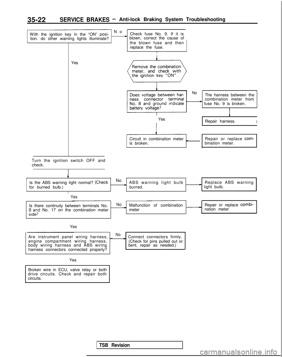
- N
o
With the ignition key in the “ON” posi-
Check fuse No. 9. If it is
tion. do other warning lights illuminate?
* blown, correct the cause of
the blown fuse and thenreplace the fuse.
I
Yes
Turn the ignition switch OFF and check.
4II., III,
Is the ABS warning light normal? (CheckNo cABS warning light bulb Replace ABS warning
for burned bulb.)burned.* light bulb.
I
Yes
NoThe harness between the
combination meter from
* fuse No. 9 is broken.
1
Repair harness.I
Circuit in combination metercRepair or replace com-
is broken. bination meter.
Yes
Is there continuity between terminals No.NoMalfunction of combination Repair or replace combi-
;,d”,l” No. 17 on the combination meter -meter
nation meter
Yes
Are instrument panel wiring harness, _
Noc Connect connectors firmly.
engine compartment wiring harness,
body wiring harness and ABS wiring
harness connectors connected properly? (Check for pins pulled out or
bent, repair as needed.)
Yes
Broken wire in ECU, valve relay or both
drive circuits. Check and repair both
circuits.
TSB Revision
Page 1158 of 1273
SERVICE BRAKES - Anti-lock Braking System Troubleshooting35-37
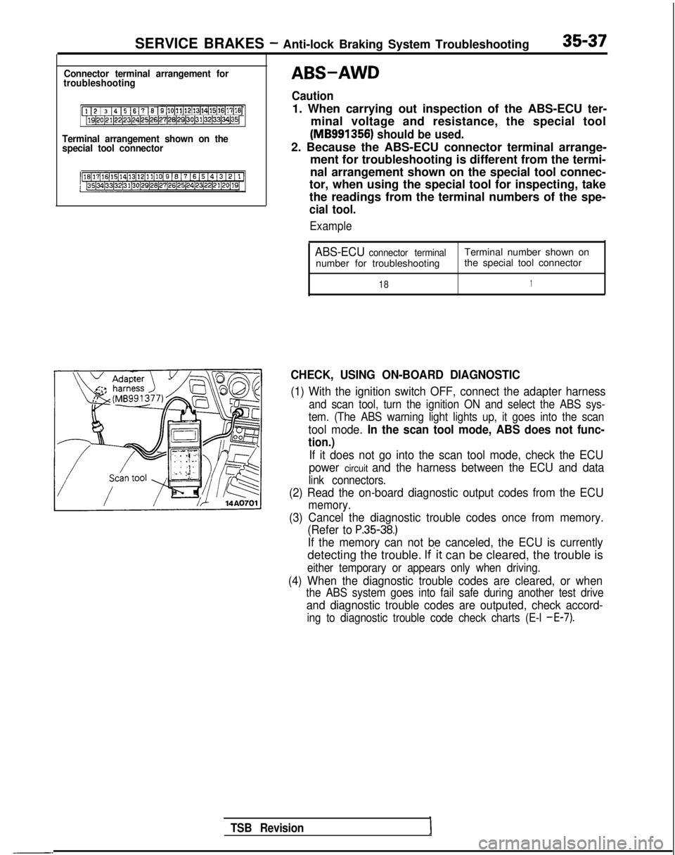
Connector terminal arrangement for
troubleshooting
[l I2 / 3 14 15 1617 16 I9[10~11~12(13~14~15(16~17[16j[lQ~20~21~22~23~24)25~26~27~28(29130~31~32~33~34~35~
Terminal arrangement shown on the
special tool connector
-.
TSB Revision
ABS-AWD
Caution
1. When carrying out inspection of the ABS-ECU ter-
minal voltage and resistance, the special tool
(MB991356) should be used.
2. Because the ABS-ECU connector terminal arrange- ment for troubleshooting is different from the termi-
nal arrangement shown on the special tool connec-
tor, when using the special tool for inspecting, take
the readings from the terminal numbers of the spe-
cial tool.
Example
ABS-ECU connector terminalTerminal number shown on
number for troubleshooting the special tool connector
181
CHECK, USING ON-BOARD DIAGNOSTIC
(1) With the ignition switch OFF, connect the adapter harness
and scan tool, turn the ignition ON and select the ABS sys-
tem. (The ABS warning light lights up, it goes into the scan
tool mode. In the scan tool mode, ABS does not func-
tion.)
If it does not go into the scan tool mode, check the ECU
power
circuit and the harness between the ECU and data
link connectors.
(2) Read the on-board diagnostic output codes from the ECU
memory.
(3) Cancel the diagnostic trouble codes once from memory. (Refer to
P.35-38.)
If the memory can not be canceled, the ECU is currently
detecting the trouble. If’it can be cleared, the trouble is
either temporary or appears only when driving.
(4) When the diagnostic trouble codes are cleared, or when
the ABS system goes into fail safe during another test drive
and diagnostic trouble codes are outputed, check accord-
ing to diagnostic trouble code check charts (E-l -E-7).
Page 1161 of 1273

SERVICE BRAKES - Anti-lock Braking System Troubleshooting
W
ith the ignition key in the “ON” posi- No
Check fuse No. 9. If it is
tion, do other warning lights illuminate? blown, correct the cause of
-T-
Yesthe blown fuse and then
replace the fuse.I
Remove the combination
meter, and check with
the ignition key “ON”.
I
Does voltage between har-NoThe harness between the ness
connector terminal
No. 8 and ground indicate
-combination meter from
fuse No. 9 is broken.
battery voltage?
I
Yes Repair harness.
Circuit in combination meter
is broken.
L Repair or replace com-
bination meter.
Turn the ignition switch OFF an
check.
I
Is the ABS warning light normal? (CheckNo
for burned bulb.)c A$Eedyrning light bulb
,
c Replace ABS warning
light bulb.
Yes
Is there continuity between terminals No. No -
8 and 4” or 17’2 on the combinationI Malfunction of combinatio
n
meter
I Repair or replace combi-
meter side? nation meter
Are instrument panel wiring harness, No
-~
engine compartment wiring harness, . Connect connectors firmly.
body wiring harness and ABS wiring
(Check for pins pulled out or
harness connectors connected properly? bent, repair as needed.)
I
1 Yes
I
Broken wire in ECU, valve relay or both
drive circuits. Check and repair both
circuits.
I
NOTE‘1: Non-Turbo . Turbol *:Non-Turbo
TSB Revision
Page 1191 of 1273
35-70SERVICE BRAKES- Service Adjustment Procedures
I, ! I ! I4 IO II IIWhen turned manually :---;---i-.-l---L--.I 8 ! IaI 1 11 1 II ’I 1’ I I I;-;--1---:--‘---+---t---i ’I IL---)-.-i---+--.II ’ I I 1 , 1 ,I
--:--~---;---:---~--~--
POINTS IN WAVEFORM MEASUREMENT
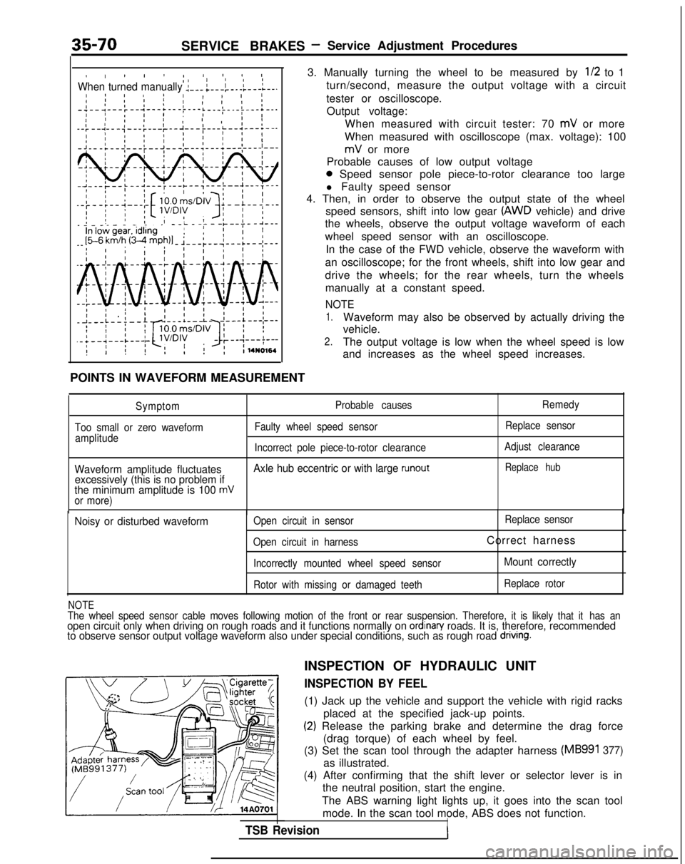
3. Manually turning the wheel to be measured by
l/2 to 1
turn/second, measure the output voltage with a circuit
tester or oscilloscope. Output voltage: When measured with circuit tester: 70
mV or more
When measured with oscilloscope (max. voltage): 100
mV or more
Probable causes of low output voltage
0 Speed sensor pole piece-to-rotor clearance too large
l Faulty speed sensor
4. Then, in order to observe the output state of the wheel
speed sensors, shift into low gear
(AWD vehicle) and drive
the wheels, observe the output voltage waveform of each
wheel speed sensor with an oscilloscope.
In the case of the FWD vehicle, observe the waveform with
an oscilloscope; for the front wheels, shift into low gear and
drive the wheels; for the rear wheels, turn the wheels manually at a constant speed.
NOTE
1.Waveform may also be observed by actually driving the
vehicle.
2.The output voltage is low when the wheel speed is low
and increases as the wheel speed increases.
Symptom
Too small or zero waveform amplitude Probable causes
Faulty wheel speed sensor Remedy
Replace sensor
Incorrect pole piece-to-rotor clearanceAdjust clearance
Waveform amplitude fluctuates Axle hub eccentric or with large runoutReplace hub
excessively (this is no problem if
the minimum amplitude is 100 mVor more)
Noisy or disturbed waveformOpen circuit in sensor Replace
sensor
Open circuit in harness
Correct harness
Incorrectly mounted wheel speed sensorMount correctly
Rotor with missing or damaged teeth Replace rotor
NOTEThe wheel speed sensor cable moves following motion of the front or rear\
suspension. Therefore, it is likely that it
has anopen circuit only when driving on rough roads and it functions normally \
on ordinan/ roads. It is, therefore, recommended
to observe sensor output voltage waveform also under special conditions,\
such as rough road dnvlng.
TSB Revision
INSPECTION OF HYDRAULIC UNIT
INSPECTION BY FEEL
(1) Jack up the vehicle and support the vehicle with rigid racks
placed at the specified jack-up points.
(2) Release the parking brake and determine the drag force(drag torque) of each wheel by feel.
(3) Set the scan tool through the adapter harness
(MB991 377)
as illustrated.
(4) After confirming that the shift lever or selector lever is in the neutral position, start the engine.
The ABS warning light lights up, it goes into the scan tool mode. In the scan tool mode, ABS does not function.
I
Page 1193 of 1273
35-72SERVICE BRAKES - Service Adjustment Procedures
14AO701 1
INSPECTION BY USING BRAKE FORCE TESTER
NOTE
(1) The brake force tester roller and tire must be dry during thetest.
(2) When testing the front brakes, apply the parking brake and when testing the rear brakes, apply chocks to the front
wheels to lock them.
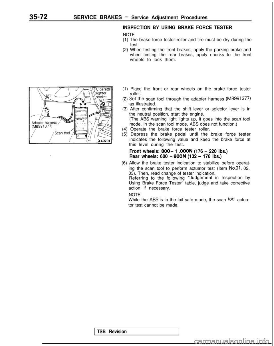
(1) Place the front or rear wheels on the brake force tester
(2) &(%:he
scan tool through the adapter harness (MB991377)
as illustrated.
(3) After confirming that the shift lever or selector lever is in
the neutral position, start the engine.(The ABS warning light lights up, it goes into the scan tool
mode. In the scan tool mode, ABS does not function.)
(4) Operate the brake force tester roller.
(5) Depress the brake pedal until the brake force tester
indicates the following value and keep the brake force at
this level during the test.
Front wheels: 800- 1 ,OOON (176 - 220 Ibs.)
Rear wheels: 600
- 800N (132 - 176 Ibs.)
(6) Allow the brake tester indication to stabilize before operat-
ing the scan tool to perform actuator test (Item
No.01, 02,
03). Then, read change of tester indication. Referring to the following “Judgement in Inspection by
Using Brake Force Tester” table, judge and take corrective
action if necessary.
NOTE
While the ABS is in the fail safe mode, the scan tOOf actua-
tor test cannot be made.
TSB Revision