parking brake MITSUBISHI GALANT 1989 Service Repair Manual
[x] Cancel search | Manufacturer: MITSUBISHI, Model Year: 1989, Model line: GALANT, Model: MITSUBISHI GALANT 1989Pages: 1273, PDF Size: 37.62 MB
Page 1 of 1273
BACKUP
Service Manual
GRLRNT
1989-1990-1991-1992-1993
Volume 1
Chassis & Mechanical
FOREWORD
This Service Manual has been prepared with thelatest service information available at the time of
publication. It is subdivided into various group cate-
gories and each section contains diagnostic, dis-
assembly, repair, and installation procedures along
with complete specifications and tightening ref-
erences. Use of this manual will aid in properly per-
forming any servicing necessary to maintain or res-
tore the high levels of performance and reliability
designed into these outstanding vehicles.
This BACKUP DSM manual is to be used DNLY as
a SACKUP. please DIJ NOT REDISTRIBUTEWHOLE SECTIONS. This BACKUP was sold to you under the fact that you do indeed
DWNa GENUINE DSM MANUAL. It CANNOT BE considered a REPLACEMENT (Unless your
original
manual was lost or
destroyed.) Please
See
README.TXT
or
README.HTML
for additional
information.
1kyou.
- Gjmpiemym_ay&?h
@
A
.
.”
WE SUPPORT
VOLUNTARY TECHNICIAN
CERTIFICATION THROUGH
Nallonal lnsrltule forAU~~~v3~;VPCT:VE
EXCELLENCE naiLcorn
MITSUBISHIMOTOR SALES OF AMERICA. Inc.
Mltsublshl Motors Corporat!on reserves the right to make changes indesign or to make additions to or Improvements In Its products
wlthout~mposng any obllgatlons upon Itself to install them on its productspreviously manufactured
0 1992 Mitsubishi Motors CorporationRcprintedinUSA
GROUP INDEXMOOAA-
General.........................................................
Engine...........................................................
Fuel................................................................
Cooling.........................................................
Intake and Exhaust..............................
Emission Control....................................
Clutch............................................................
Manual Transaxle..................................
Automatic Transaxle............................
Propeller Shaft........................................
Front Axle..................................................
Rear Axle....................................................
Wheel and Tire.......................................
Power Plant Mount..............................
Front Suspension...................................
Active-Electronic
Control Suspension..............................m
A
Rear Suspension....................................&
Service Brakes.........................................
Parking Brakes........................................
Alphabetical Index.................................
NOTE: Electrical system Information is contained in
Volume 2 “Electrical” of this paired Service Manual.
For overhaul procedures of engines or transmissions,
refer to the separately issued Engine
Service Manual
or Manual/Automatic Transmission Service Manual.
Page 19 of 1273
GENERAL - Towina and Hoisting
00-l 7
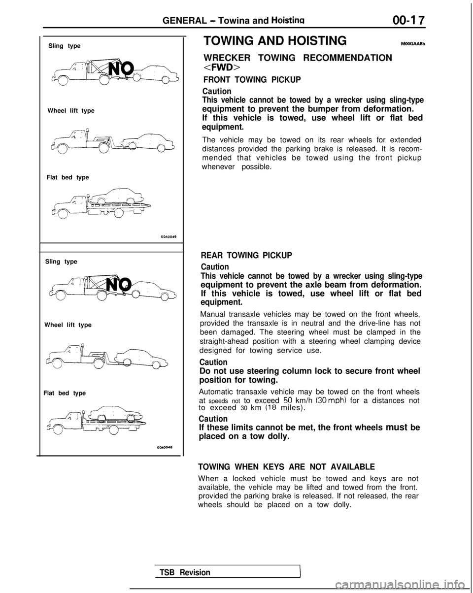
Sling type
Wheel lift type
Flat bed type
Sling type
Wheel lift type
Flat bed type TOWING AND HOISTING
WRECKER TOWING RECOMMENDATION
FRONT TOWING PICKUP
Caution
This vehicle cannot be towed by a wrecker using sling-type
equipment to prevent the bumper from deformation.
If this vehicle is towed, use wheel lift or flat bed
equipment.
The vehicle may be towed on its rear wheels for extended
distances provided the parking brake is released. It is recom-
mended that vehicles be towed using the front pickup
whenever possible.
REAR TOWING PICKUP
Caution
This vehicle cannot be towed by a wrecker using sling-type
equipment to prevent the axle beam from deformation. If this vehicle is towed, use wheel lift or flat bed
equipment.
Manual transaxle vehicles may be towed on the front wheels,
provided the transaxle is in neutral and the drive-line has not
been damaged. The steering wheel must be clamped in the
straight-ahead position with a steering wheel clamping device
designed for towing service use.
Caution
Do not use steering column lock to secure front wheel
position for towing.
Automatic transaxle vehicle may be towed on the front wheels at speeds not to exceed
50 km/h (30 mob) for a distances not
to exceed 30 km (18 miles).
Caution
If these limits cannot be met, the front wheels must be
placed on a tow dolly.
TOWING WHEN KEYS ARE NOT AVAILABLE
When a locked vehicle must be towed and keys are not available, the vehicle may be lifted and towed from the front.provided the parking brake is released. If not released, the rear
wheels should be placed on a tow dolly.
TSB Revision
Page 22 of 1273
00-20GENERAL - Special Handling Instructions for AWD Models
SPECIAL HANDLING INSTRUCTIONS
FOR AWD MODELS
TOWIN
G
MomMA
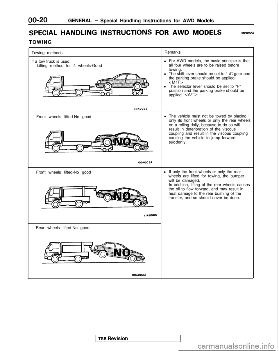
Towing methods
If a tow truck is used Lifting method for 4 wheels-Good Remarks
l For AWD models, the basic principle is that
all four wheels are to be raised before
towing.
l The shift lever should be set to 1
st gear and
the parking brake should be applied.
l The selector lever should be set to “P” position and the parking brake should be
applied.
OOA0032
Front wheels lifted-No good l The vehicle must not be towed by placing
only its front wheels or only the rear wheels
on a rolling dolly, because to do so willresult in deterioration of the viscous
coupling and result in the viscous coupling
causing the vehicle to jump forward
suddenly.
OOA0034
Front wheels lifted-No good l
If only the front wheels or only the rear
wheels are lifted for towing, the bumper
will be damaged. In addition, lifting of the rear wheels causes
the oil to flow forward, and may result in
heat damage to the rear bushing of the
transfer, and so should never be done.
Rear wheels lifted-No good
OOA0033
TSB Revision1
Page 24 of 1273
00-22GENERAL - Special Handling Instructions for AWD Models
REAR WHEEL MEASUREMENTS
After placing the rear wheels on the brake tester, follow thesame procedures as for the front wheel measurements.
WHEEL BALANCE
FRONT WHEEL MEASUREMENTS
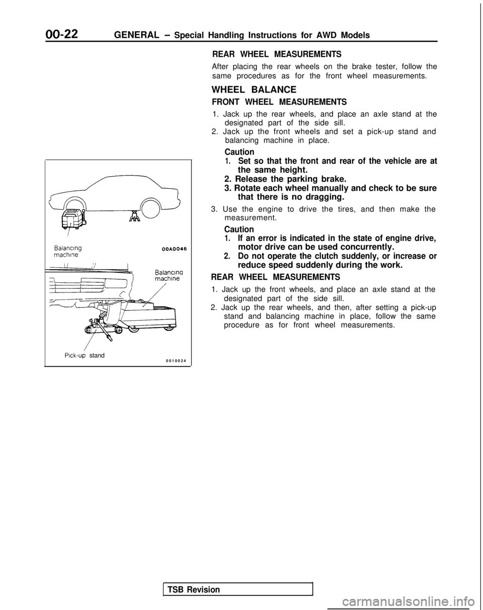
1. Jack up the rear wheels, and place an axle stand at the designated part of the side sill.
2. Jack up the front wheels and set a pick-up stand and balancing machine in place.
Caution
1.Set so that the front and rear of the vehicle are at
the same height. Balancing
machlne
OOA0046
Balancw
Pick-up stand
0010024
TSB Revision
2. Release the parking brake.
3. Rotate each wheel manually and check to be sure
that there is no dragging.
3. Use the engine to drive the tires, and then make the measurement.
Caution
1.If an error is indicated in the state of engine drive,
motor drive can be used concurrently.
2.Do not operate the clutch suddenly, or increase or
reduce speed suddenly during the work.
REAR WHEEL MEASUREMENTS
1. Jack up the front wheels, and place an axle stand at the
designated part of the side sill.
2. Jack up the rear wheels, and then, after setting a pick-up stand and balancing machine in place, follow the same
procedure as for front wheel measurements.
Page 46 of 1273
GENERAL -Maintenance Service
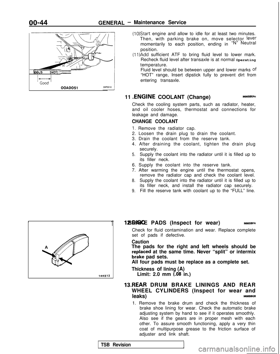
(1O)Star-t engine and allow to idle for at least two minutes.
Then, with parking brake on, move selector
fever
momentarily to each position, ending in “N” Neutral
position.
(11)Add sufficient ATF to bring fluid level to lower mark.
Recheck fluid level after transaxle is at normal Operating
temperature. Fluid level should be between upper and lower marks of
“HOT” range, Insert dipstick fully to prevent dirt from
entering transaxle.
OOA0051
11 .ENGINE
COOLANT (Change)MOOSEEAC
Check the cooling system parts, such as radiator, heater,
and oil cooler hoses, thermostat and connections for
leakage and damage.
CHANGE COOLANT
1. Remove the radiator cap.
2. Loosen the drain plug to drain the coolant.
3. Drain the coolant from the reserve tank.
4. After draining the coolant, tighten the drain plug securely.
5.Supply the coolant into the radiator until it is filled up to
its filler neck.
6. Supply the coolant into the reserve tank.
7. After warming the engine until the thermostat opens, remove the radiator cap and check the coolant level.
8.Supply the coolant into the radiator until it is filled up to
its filler neck, and install the radiator cap securely.
9.Fill the reserve tank with coolant up to the “FULL” line.
14K512
1 12.DISC BRAKE PADS (Inspect for wear) MWSBFA
Check for fluid contamination and wear. Replace complete
set of pads if defective.
Caution
The pads for the right and left wheels should be
reDlaced at the same time. Never “split” or intermix
brkke pad sets.
All four pads must be replace as a complete set.
Thickness of lining (A)
Limit: 2.0 mm (.08 in.)
13.REAR DRUM BRAKE LININGS AND REAR
WHEEL CYLINDERS (Inspect for wear and
leaks)MOOSBGB
1. Remove the brake drum and check the thickness of brake shoe lining for wear. Check the automatic brake
adjusting system by hand to see if it operates smoothly.
Also see if the gears are in proper mesh with each
other. To assure smooth functioning, apply a very thin
coat of multipurpose grease to the friction surface of
adjuster and link shaft.
TSB Revision1
Page 732 of 1273
23-26AUTOMATIC TRANSAXLE - Troubleshooting
HOT
TFA0715
AW
D
TFA0700
DATA LINK AND TEST
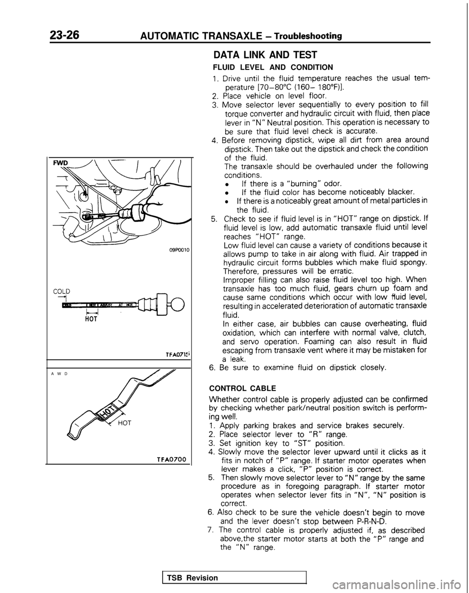
FLUID LEVEL AND CONDITION
1. Drive until the
fluid
temperature
reaches the
usual tem-
perature
[70-80°C (160- 18O”F)l.
2. Place
vehicle
on level floor.
3. Move
selector
lever sequentially
to
every
position
to fill
torque
converter
and hydraulic circuit
with fluid,
then
place
lever in “N” Neutral position.
This operation is necessary
t0
be sure that fluid
level check is accurate.
4. Before
removing
dipstick,
wipe all dirt from area around
dipstick.
Then take out
the
dipstick
and check the
condition
of the
fluid.
The
transaxle
should be overhauled under the following
conditions.
l If there
is a “burning” odor.
l If the
fluid
color
has become
noticeably
blacker.
lIf there
is a noticeably
great
amount
of metal particles in
the
fluid.
5.Check to
see if fluid
level is in “HOT” range on dipstick.
If
fluid
level is low, add automatic
transaxle
fluid
until level
reaches “HOT” range.
Low
fluid
level can cause a variety of
conditions
because it
allows
pump
to
take
in air along with fluid. Air trapped in
hydraulic circuit
forms
bubbles
which
make fluid
spongy.
Therefore,
pressures
will be erratic. Improper filling
can also raise fluid level too
high. When
transaxle
has too
much fluid,
gears churn up foam and
cause same
conditions
which occur with low fluid
level, resulting
in accelerated deterioration
of
automatic
transaxle
fluid.
In
either
case, air bubbles
can cause overheating,
fluid
oxidation,
which can interfere
with normal valve, clutch,
and
servo
operation.
Foaming can also result
in fluid
escaping
from
transaxle
vent where it
may be mistaken
for
a leak.
6. Be
sure to
examine
fluid
on dipstick
closely.
CONTROL CABLE
Whether control
cable is properly
adjusted
can be confirmed
by
checking
whether park/neutral
position
switch is perform-
ing
well.
1.
Apply
parking brakes and service
brakes securely.
2. Place
selector
lever
to
“R” range.
3. Set ignition
key to
“ST” position.
4.
Slowly
move
the
selector
lever
upward
until it
clicks as it
fits in
notch of “P” range. If starter
motor
operates
when
lever makes a click, “P”
position
is correct.
5.Then slowly
move
selector
lever to “N” range by
the
same
procedure as in foregoing
paragraph. If starter
motor
operates
when selector
lever
fits in ‘IN”, “N” position
is correct.
6.
Also check to be sure the
vehicle
doesn’t
begin to move
and
the
lever
doesn’t
stop
between
P-R-N-D.
7. The control
cable is properly
adjusted if, as described
above,the
starter
motor
starts
at both the
“P” range and the
“N” range.
TSB Revision
Page 765 of 1273
AUTOMATIC TRANSAXLE - Troubleshooting23-59
ring
brake
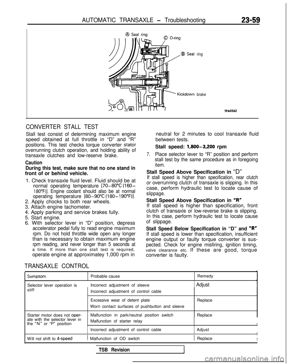
CONVERTER STALL TEST
Stall test consist of determining maximum engine
speed obtained at full throttle in “D” and “R”
positions. This test checks torque converter stator
overrunning clutch operation, and holding ability of
transaxle clutches and low-reserve brake.
Caution
During this test, make sure that no one stand in
front of or behind vehicle.
1. Check transaxle fluid level. Fluid should be at
normal operating temperature [70-80°C (160-
18O”F)j. Engine coolant should also be at normal
operating temperature
[80-90°C (180-19O”F)l.
2. Apply chocks to both rear wheels.
3. Attach engine tachometer.
4. Apply parking and service brakes fully.
5. Start engine.
6. With selector lever in “D” position, depress
accelerator pedal fully to read engine maximum
rpm. Do not hold throttle wide open any longer
than is necessary to obtain maximum engine
rpm reading, and never longer than 5 seconds at
a time. If more than one stall test is required,
operate engine at approximatey 1,000 rpm in
TRANSAXLE CONTROL
neutral for 2 minutes to cool transaxle fluid
between tests.
Stall speed: 1,800-3,200
rpm
7.Place selector lever to “R” position and perform
stall test by the same procedure as in foregoing
item.
Stall Speed Above Specification in “D”
If stall speed is higher than specification, rear clutch
or overrunning clutch of transaxle is slipping. In this
case, perform hydraulic test to locate cause of
slippage.
Stall Speed Above Specification in “I?”
If stall speed is higher than specification, front
clutch of transaxle or low-reverse brake is slipping. In this case, perform hydraulic test to locate cause
of slippage.
Stall Speed Below Specification in “D” and “R”
If stall speed is lower than specification, insufficient
engine output or faulty torque converter is sus-
pected. Check for engine misfiring, ignition timing,
valve clearance etc. If these are good, torque
converter is faulty. Svmotom
Probable cause
Remedy
Selector lever operation is Incorrect adjustment of sleeve
1 Adjust
stiff
Starter motor does not oper-
Incorrect adjustment of control cable
Excessive wear of detent plate
Worn contact surfaces of pushbutton and sleeve
Malfunction in park/neutral position switch Replace
Replace
ate with the selector lever in
the
“N” or “P” position Malfunction of starter relayI
Incorrect adjustment of control cable
AdjustI
W
ill not shift to 4-speed
( Malfunction of OD switch) ReplaceI
TSB Revision
Page 864 of 1273
27-4REAR AXLE
11 PO033
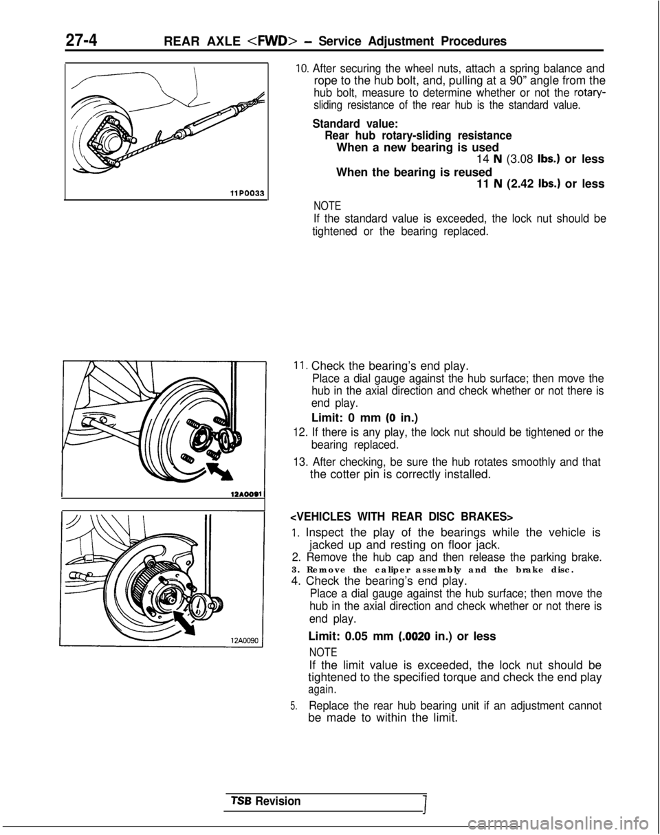
10. After securing the wheel nuts, attach a spring balance and
rope to the hub bolt, and, pulling at a 90” angle from the
hub bolt, measure to determine whether or not the rotary-
sliding resistance of the rear hub is the standard value.
Standard value: Rear hub rotary-sliding resistance
When a new bearing is used 14
N (3.08 Ibs.) or less
When the bearing is reused 11
N (2.42 Ibs.) or less
NOTE
If the standard value is exceeded, the lock nut should be
tightened or the bearing replaced.
11. Check the bearing’s end play.
Place a dial gauge against the hub surface; then move the
hub in the axial direction and check whether or not there is
end play.
Limit: 0 mm (0 in.)
12. If there is any play, the lock nut should be tightened or the
bearing replaced.
13. After checking, be sure the hub rotates smoothly and that
the cotter pin is correctly installed.
1. Inspect the play of the bearings while the vehicle is jacked up and resting on floor jack.
2. Remove the hub cap and then release the parking brake.
3. Remove the caliper assembly and the brake disc.
4. Check the bearing’s end play.
Place a dial gauge against the hub surface; then move the
hub in the axial direction and check whether or not there is
end play.
Limit: 0.05 mm (.0020 in.) or less
NOTE
If the limit value is exceeded, the lock nut should be
tightened to the specified torque and check the end play
again.
5.Replace the rear hub bearing unit if an adjustment cannot
be made to within the limit.
TSB RevisionI
Page 865 of 1273
REAR AXLE
REAR HUB ROTARY-SLIDING !RESlSTANCE
(TORQUE) ADJUSTMENTMZ7FCAC
1.
2.
3.
4.
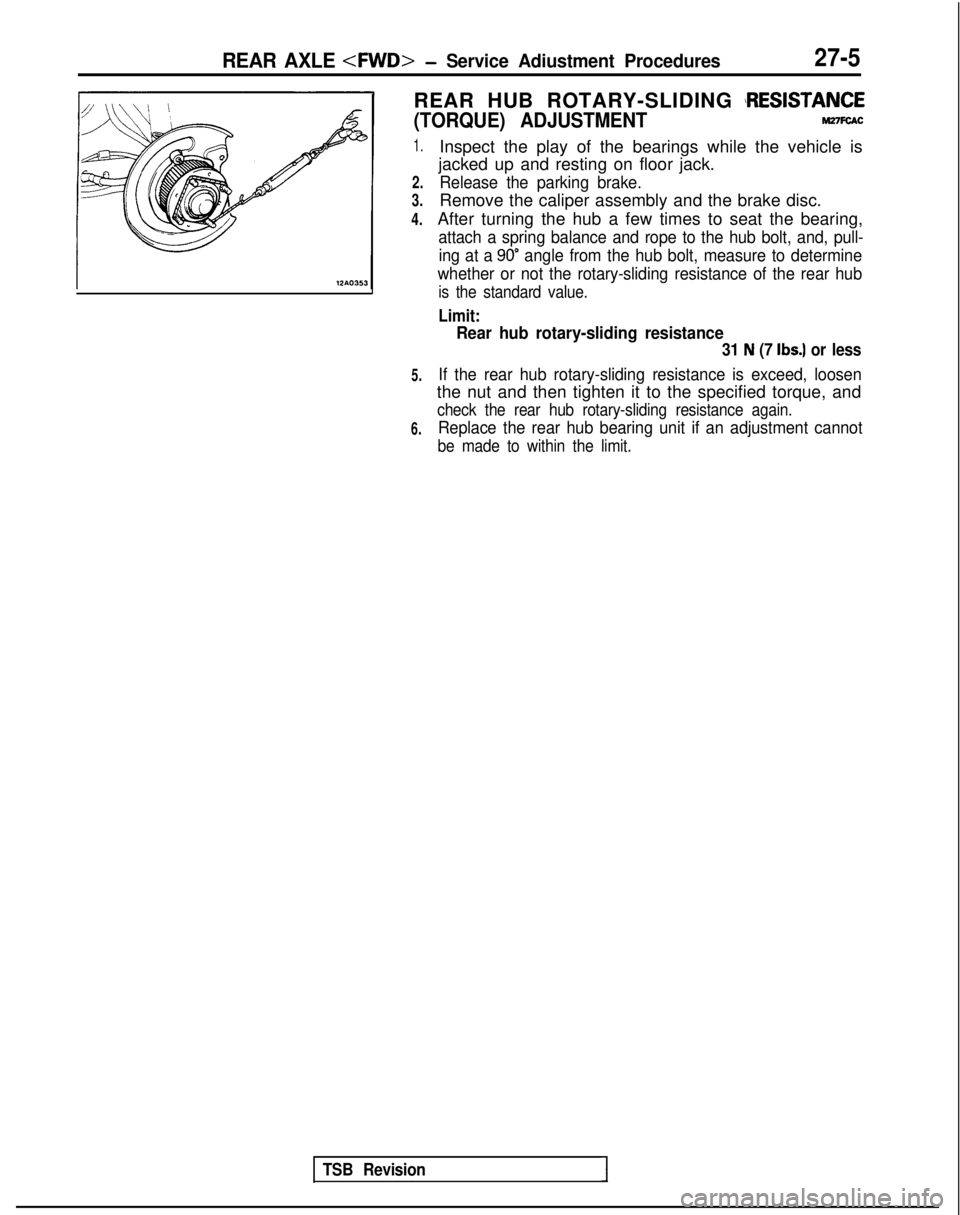
Inspect the play of the bearings while the vehicle is
jacked up and resting on floor jack.
Release the parking brake.
Remove the caliper assembly and the brake disc.
After turning the hub a few times to seat the bearing,
attach a spring balance and rope to the hub bolt, and, pull- ing at a
90” angle from the hub bolt, measure to determine
whether or not the rotary-sliding resistance of the rear hub
is the standard value.
Limit:
5.
6.
Rear hub rotary-sliding resistance
31 N (7 Ibs.) or less
If the rear hub rotary-sliding resistance is exceed, loosen
the nut and then tighten it to the specified torque, and
check the rear hub rotary-sliding resistance again.
Replace the rear hub bearing unit if an adjustment cannot
be made to within the limit.
TSB Revision1
Page 875 of 1273
REAR AXLE
Matina marks/I
1
SERVICE ADJUSTMENT PROCEDURES
REAR AXLE TOTAL BACKLASH CHECKMZ’IFAAF
If the vehicle vibrates and produces a booming sound due to an
imbalance of the driving system, measure the rear axle total
backlash by the following procedures to see if the differential
carrier assembly requires removal.
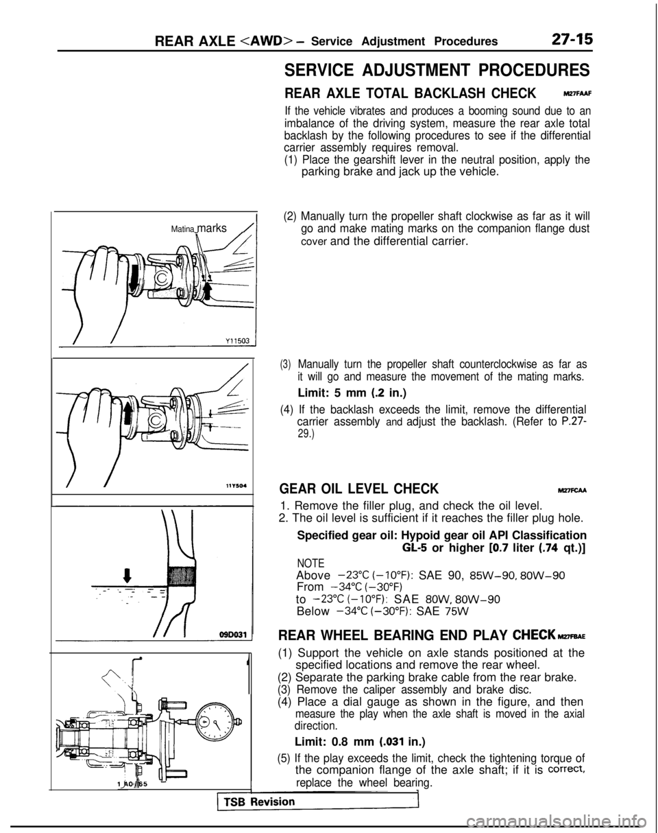
(1) Place the gearshift lever in the neutral position, apply the
parking brake and jack up the vehicle.
(2) Manually turn the propeller shaft clockwise as far as it will go and make mating marks on the companion flange dust
cover and the differential carrier.
(3)Manually turn the propeller shaft counterclockwise as far as
it will go and measure the movement of the mating marks.
Limit: 5 mm (.2 in.)
(4) If the backlash exceeds the limit, remove the differential carrier assembly
and adjust the backlash. (Refer to P.27-
29.)
GEAR OIL LEVEL CHECKM27FcAA
1. Remove the filler plug, and check the oil level.
2. The oil level is sufficient if it reaches the filler plug hole.
Specified gear oil: Hypoid gear oil API Classification
GL-5 or higher [0.7 liter (.74 qt.)]
NOTE
Above -23°C
(-10°F):
SAE 90, 85W-90,
8OW-90
From -34°C
(-30°F)
to
-23°C (-10°F): SAE 8OW, 8OW-90
Below -34°C
(-30°F):
SAE
75W
REAR WHEEL BEARING END PLAY CHECK~FBAE
(1) Support the vehicle on axle stands positioned at the
specified locations and remove the rear wheel.
(2) Separate the parking brake cable from the rear brake.
(3) Remove the caliper assembly and brake disc.
(4) Place a dial gauge as shown in the figure, and then
measure the play when the axle shaft is moved in the axial
direction.
Limit: 0.8 mm (.031 in.)
(5) If the play exceeds the limit, check the tightening torque of
the companion flange of the axle shaft; if it is correct,
replace the wheel bearing.llA0065 IJ d-