ESP MITSUBISHI I-MIEV 2011 User Guide
[x] Cancel search | Manufacturer: MITSUBISHI, Model Year: 2011, Model line: I-MIEV, Model: MITSUBISHI I-MIEV 2011Pages: 193, PDF Size: 12.2 MB
Page 101 of 193
Inspection and maintenance
following rough road operation E00606700383
After
operating the vehicle in rough road condi-
tions, be sure to perform the following inspection
and maintenance procedures:
l Check that the vehicle has not been damaged
by rocks, gravel, etc.
l Carefully wash the vehicle with water.
Drive the vehicle slowly while lightly depress-
ing the brake pedal in order to dry out the
brakes. If the brakes still do not function prop-
erly, we recommend you to have the brakes
checked as soon as possible.
l Remove the insects, dried grass, etc. clog-
ging the radiator core.
l Check the inside of the vehicle. If water en-
try is found, dry the carpet etc.
l Inspect the headlamps, If the headlamp bulb
is flooded with water, we recommend you to
have it drained. Braking
E00607001830
All
the parts of the brake system are critical to safe-
ty. We recommend you to have the vehicle
checked at regular intervals according to the serv-
ice booklet. CAUTION
l
Avoid
driving habits that cause heavy
braking and never “ride” the brakes by
resting your foot on the brake pedal
while driving.
It causes brake overheating and fading.
Brake system
The
service brake is divided into two brake cir-
cuits. And your vehicle is equipped with power
brakes. If one brake circuit fails, the other is availa-
ble to stop the vehicle. If you should lose the pow-
er assist for some reason, the brakes will still work.
In these situations, even if the brake pedal moves
down to the very end of its possible stroke or re-
sists being depressed, keep depressing the brake ped-
al down harder and further than usual; stop driving
as soon as possible and have the brake system re-
paired. WARNING
l Do
not turn off the electric motor unit
while your vehicle is in motion. If you
turn off the electric motor unit while driv-
ing, the power assistance for the braking
system will stop working and your brakes
will not work effectively. WARNING
l If
the power assist is lost or if either
brake hydraulic system stops working
properly, have your vehicle checked im-
mediately.
Warning lamp
The
brake warning lamp illuminates to indicate a
fault in the braking system. Refer to “Brake warn-
ing lamp” on page 4-09.
When brakes are wet
Check the brake system while driving at a low
speed immediately after starting, especially when
the brakes are wet, to confirm they work normally.
A film of water can be formed on the brake discs
or brake drums and prevent normal braking after
driving in heavy rain or through large puddles, or
after the vehicle is washed. If this occurs, dry the
brakes out by driving slowly while lightly depress-
ing the brake pedal.
When driving downhill
It is important to take advantage of regenerative
braking by shifting to the “B” (BRAKE) position
while driving on steep downhill roads in order to
prevent the brakes from overheating. Starting and driving
5-12
5
Presented by http://mmc-manuals.ru/ \251
Page 103 of 193
Anti-lock brake system (ABS)
E00607101394
The
anti-lock brake system (ABS) helps prevent
the wheels from locking during braking. This helps
maintain vehicle drivability and steering wheel han-
dling.
Driving hints
l Always keep a safe distance from the vehicle
in front of you. Even if your vehicle is equip-
ped with ABS, leave a greater braking dis-
tance when:
• Driving on gravel or snow-covered roads.
• Driving with tyre chains installed.
• Driving on uneven road surfaces.
l Operation of ABS is not restricted to situa-
tions where brakes are applied suddenly.
This system may also prevent the wheels
from locking when you drive over manholes,
steel roadwork plates, road markings, or any
uneven road surface.
l When the ABS is activated, you may feel the
brake pedal pulsation and the vibrations of
the vehicle body and steering wheel. It may
also feel as if the pedal resists being pressed.
In this situation, simply hold the brake ped-
al down firmly. Do not pump the brake,
which will result in reduced braking per-
formance.
l An operation noise may be emitted from the
bonnet room in the following situations. The
sound is associated with checking the opera-
tions of the anti-lock brake system.
At this time, you may feel a shock from the
brake pedal if you depress it. These do not in-
dicate a malfunction.
• When the electric motor switch is turnedto the “ON” position. • When the vehicle is driven for a while af-
ter the electric motor is turned on.
l The ABS can be used after the vehicle has
reached a speed over approximately 10 km/h
(6 mph). It stops working when the vehicle
slows below approximately 5 km/h (3 mph). CAUTION
l
The
ABS cannot prevent accidents. It is
your responsibility to take safety precau-
tions and to drive carefully.
l To prevent failure of the ABS, be sure
wheels and tyres are of the specified size
and the same type.
l Do not install any aftermarket limited-
slip differential (LSD) on your vehicle.
The ABS may stop functioning properly.
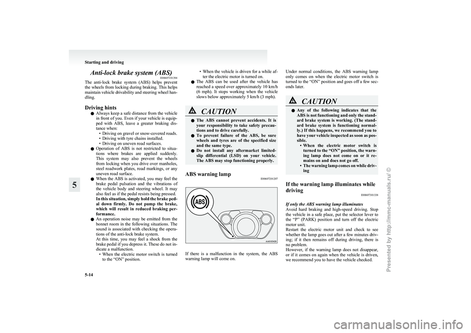
ABS warning lamp E00607201207 If there is a malfunction in the system, the ABS
warning lamp will come on.Under normal conditions, the ABS warning lamp
only
comes on when the electric motor switch is
turned to the “ON” position and goes off a few sec-
onds later. CAUTION
l
Any
of the following indicates that the
ABS is not functioning and only the stand-
ard brake system is working. (The stand-
ard brake system is functioning normal-
ly.) If this happens, we recommend you to
have your vehicle inspected as soon as pos-
sible. • When the electric motor switch isturned to the “ON” position, the warn-
ing lamp does not come on or it re-
mains on and does not go off.
• The warning lamp comes on while driv- ing
If the warning lamp illuminates while
driving E00607301338
If only the ABS warning lamp illuminates
Avoid
hard braking and high-speed driving. Stop
the vehicle in a safe place, put the selector lever to
the “P” (PARK) position and turn off the electric
motor unit.
Restart the electric motor unit and check to see
whether the lamp goes out after a few minutes driv-
ing; if it then remains off during driving, there is
no problem.
However, if the warning lamp does not disappear,
or if it comes on again when the vehicle is driven,
we recommend you to have the vehicle checked. Starting and driving
5-14
5
Presented by http://mmc-manuals.ru/ \251
Page 105 of 193
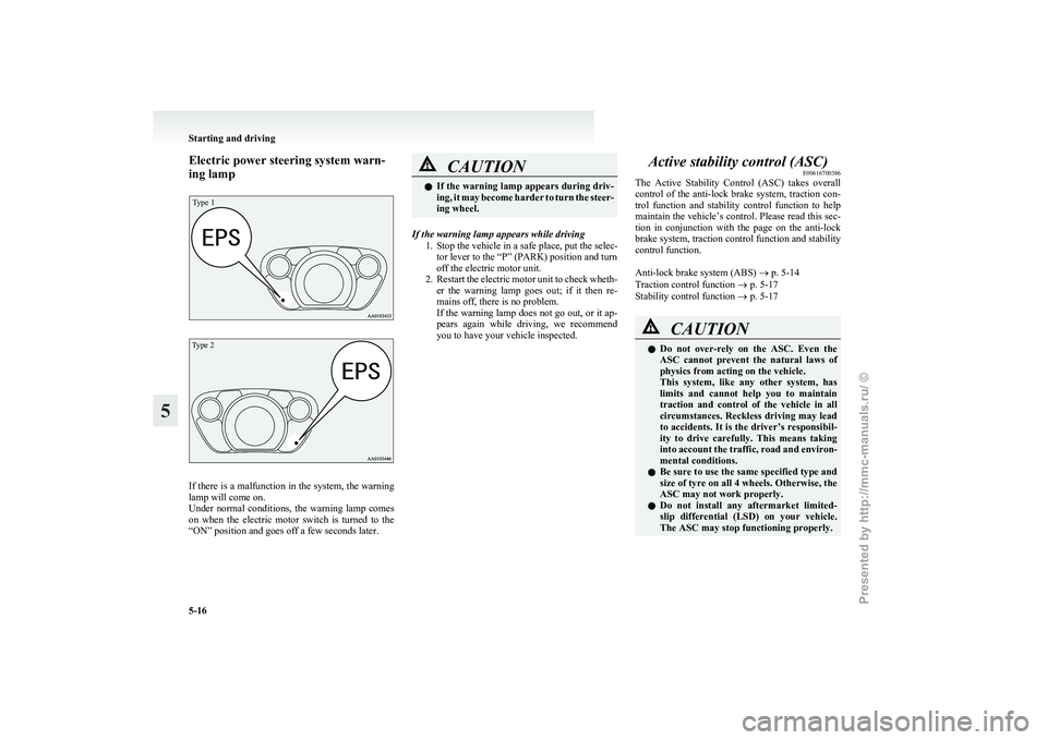
Electric power steering system warn-
ing lampType 1
Type 2
If there is a malfunction in the system, the warning
lamp will come on.
Under
normal conditions, the warning lamp comes
on when the electric motor switch is turned to the
“ON” position and goes off a few seconds later. CAUTION
l
If
the warning lamp appears during driv-
ing, it may become harder to turn the steer-
ing wheel.
If the warning lamp appears while driving 1.
Stop the vehicle in a safe place, put the selec-tor lever to the “P” (PARK) position and turn
off the electric motor unit.
2. Restart the electric motor unit to check wheth- er the warning lamp goes out; if it then re-
mains off, there is no problem.
If the warning lamp does not go out, or it ap-
pears again while driving, we recommend
you to have your vehicle inspected. Active stability control (ASC)
E00616700386
The
Active Stability Control (ASC) takes overall
control of the anti-lock brake system, traction con-
trol function and stability control function to help
maintain the vehicle’s control. Please read this sec-
tion in conjunction with the page on the anti-lock
brake system, traction control function and stability
control function.
Anti-lock brake system (ABS) ® p. 5-14
Traction control function ® p. 5-17
Stability control function ® p. 5-17 CAUTION
l
Do
not over-rely on the ASC. Even the
ASC cannot prevent the natural laws of
physics from acting on the vehicle.
This system, like any other system, has
limits and cannot help you to maintain
traction and control of the vehicle in all
circumstances. Reckless driving may lead
to accidents. It is the driver’s responsibil-
ity to drive carefully. This means taking
into account the traffic, road and environ-
mental conditions.
l Be sure to use the same specified type and
size of tyre on all 4 wheels. Otherwise, the
ASC may not work properly.
l Do not install any aftermarket limited-
slip differential (LSD) on your vehicle.
The ASC may stop functioning properly. Starting and driving
5-16
5
Presented by http://mmc-manuals.ru/ \251
Page 142 of 193
NOTE
l If
genuine leather is wet with water or is wash-
ed in water, wipe off water as quickly as pos-
sible with a dry, soft cloth. If left damp, mil-
dew may grow.
l The genuine leather surface may be damaged
if a nylon brush or synthetic fibre is rubbed
hard against it.
l Organic solvents such as benzine, kerosene,
alcohol and petrol, acid or alkaline solvents
may discolour the genuine leather surface.
Be sure to use neutral detergents.
l Remove dirty patches or oil substances quick-
ly as they can stain genuine leather.
l The genuine leather surface may harden and
shrink if it is exposed to direct sun for long
hours. When your vehicle is parked, place it
in the shade as much as possible. Cleaning the exterior of your
vehicle E08400600010
If
the following is left on your vehicle, it may
cause corrosion, discolouration and stains, wash
the vehicle as soon as possible.
l Seawater, road deicing products.
l Soot and dust, iron powder from factories,
chemical substance (acids, alkalis, coal-tar,
etc.).
l Droppings from birds, carcasses of insects,
tree sap, etc.
Washing E08400700011
Chemicals contained in the dirt and dust picked up
from
the road surface can damage the paint coat
and body of your vehicle if left in prolonged contact.
Frequent washing and waxing is the best way to pro-
tect your vehicle from this damage. This will also
be effective in protecting it from environmental el-
ements such as rain, snow, salt air, etc.
Do not wash the vehicle in direct sunlight. Park the
vehicle in the shade and spray it with water to re-
move dust. Next, using an ample amount of clean
water and a car washing brush or sponge, wash the
vehicle from top to bottom.
Use a mild car washing soap if necessary. Rinse
thoroughly and wipe dry with a soft cloth. After
washing the vehicle, carefully clean the joints and
flanges of the doors, bonnet and other sections
where dirt is likely to remain. WARNING
l Do
not wash the vehicle while charging
the traction battery.
Doing so could cause fire or an electric
shock.
l Before washing the vehicle, make sure
that the charging lid and the inner lid are
completely closed.
If the lid is open, the charging unit is ex-
posed to water, resulting in fire or an elec-
tric shock.
l Do not pour water inside the electric mo-
tor unit room. Doing so could cause fire
or an electric shock.
l When washing the vehicle, turn the elec-
tric motor switch to the “LOCK” position.
l Do not use a high pressure washing ma-
chine to clean the underneath of the vehi-
cle.
Doing so might cause the electric motor
unit problem or malfunction.
l When washing the underside of your vehi-
cle or wheel, be careful not to injure your
hands.
l Refrain from excessively using a car wash
as its brushes may scratch the paint sur-
face, causing it to lose its gloss. Scratches
will be especially visible on darker col-
oured vehicles.
l Never spray or splash water on the electri-
cal components in the bonnet room.
Exercise caution also when washing the
underbody; be careful not to spray water
into the bonnet room.
l Some types of hot water washing equip-
ment apply high pressure and heat to the Vehicle care and Maintenance
8-03 8
Presented by http://mmc-manuals.ru/ \251
Page 145 of 193
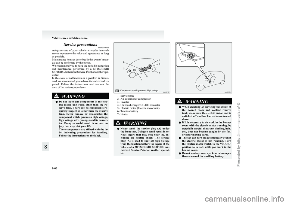
Service precautions
E08401700018
Adequate
care of your vehicle at regular intervals
serves to preserve the value and appearance as long
as possible.
Maintenance items as described in this owner’s man-
ual can be performed by the owner.
We recommend you to have the periodic inspection
and maintenance performed by a MITSUBISHI
MOTORS Authorized Service Point or another spe-
cialist.
In the event a malfunction or a problem is discov-
ered, we recommend you to have it checked and re-
paired. Follow the instructions and cautions for
each of the various procedures. WARNING
l Do
not touch any components in the elec-
tric motor unit room other than the re-
serve tank. There are no components re-
quiring inspection other than the reserve
tank. Never remove or disassemble the
component which generates high voltage,
high voltage wire (orange) and its connec-
tor. Doing so could result in serious in-
jury that may risk your life.
These components are affixed with the la-
bel indicating precautions for handling.
Follow the instructions on the label.
: Components which generates high voltage. 1- Service plug
2-
Air conditioner compressor
3- Inverter
4- On board charger/DC-DC converter
5- Electric motor (Electric motor unit)
6- Traction battery
7- Heater WARNING
l Never
touch the service plug (A) under
the front seat. Doing so could result in se-
rious injury that may risk your life, in-
cluding an electric shock. The service
plug (A) is used to shut off high voltage
from the traction battery for repair of the
vehicle at a MITSUBISHI MOTORS Au-
thorized Service Point or another special-
ist. WARNING
l When
checking or servicing the inside of
the bonnet room and coolant reserve
tank, make sure the electric motor unit is
switched off and has had a chance to cool
down.
l If it is necessary to do work in the bonnet
room with the electric motor running, be
especially careful that your clothing, hair,
etc., does not become caught by the fan,
or other moving parts.
l The fan can turn on automatically even if
the electric motor is not running. Turn
the electric motor switch to the “LOCK”
position to be safe while you work in the
bonnet room.
l Do not smoke, cause sparks or allow open
flames around the auxiliary battery. Vehicle care and Maintenance
8-06
8
Presented by http://mmc-manuals.ru/ \251
Page 151 of 193
Auxiliary battery
E08402300011
The
condition of the auxiliary battery is very impor-
tant to keep the vehicle’s electrical system working
properly. Regular inspection and care are especial-
ly important in cold weather.
Removing and installing the auxiliary
battery upper cover E08402400012
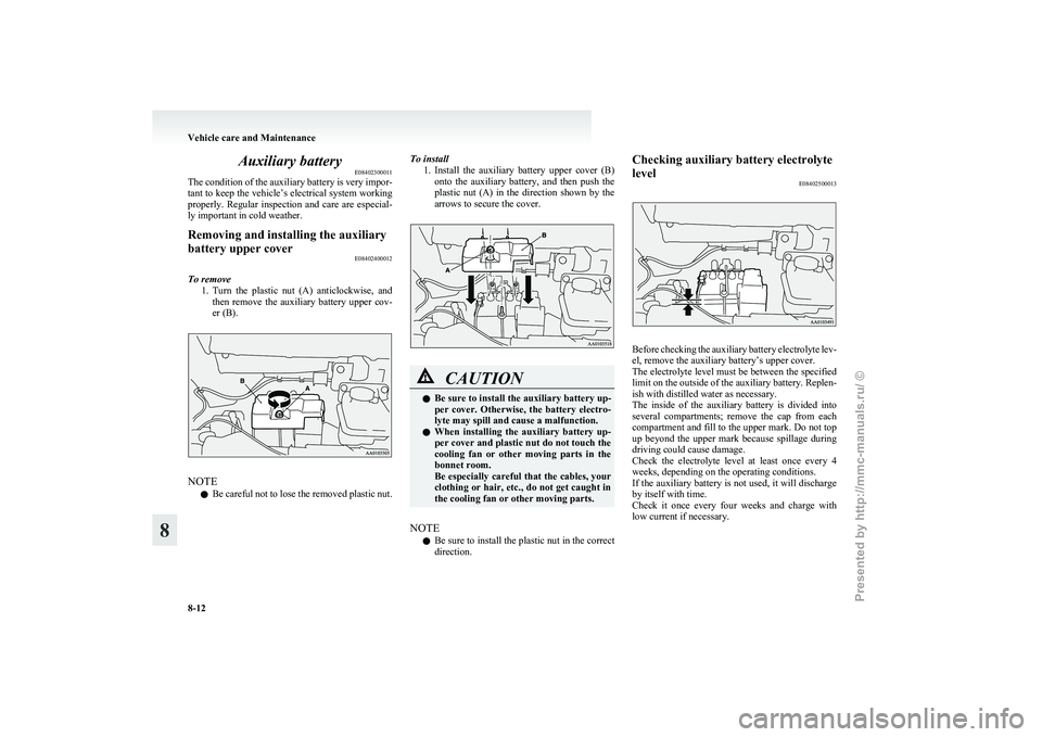
To remove 1. Turn
the plastic nut (A) anticlockwise, and
then remove the auxiliary battery upper cov-
er (B). NOTE
l Be
careful not to lose the removed plastic nut. To install
1. Install
the auxiliary battery upper cover (B)
onto the auxiliary battery, and then push the
plastic nut (A) in the direction shown by the
arrows to secure the cover. CAUTION
l
Be sure to install the auxiliary battery up-
per
cover. Otherwise, the battery electro-
lyte may spill and cause a malfunction.
l When installing the auxiliary battery up-
per cover and plastic nut do not touch the
cooling fan or other moving parts in the
bonnet room.
Be especially careful that the cables, your
clothing or hair, etc., do not get caught in
the cooling fan or other moving parts.
NOTE l Be
sure to install the plastic nut in the correct
direction. Checking auxiliary battery electrolyte
level
E08402500013 Before checking the auxiliary battery electrolyte lev-
el, remove the auxiliary battery’s upper cover.
The
electrolyte level must be between the specified
limit on the outside of the auxiliary battery. Replen-
ish with distilled water as necessary.
The inside of the auxiliary battery is divided into
several compartments; remove the cap from each
compartment and fill to the upper mark. Do not top
up beyond the upper mark because spillage during
driving could cause damage.
Check the electrolyte level at least once every 4
weeks, depending on the operating conditions.
If the auxiliary battery is not used, it will discharge
by itself with time.
Check it once every four weeks and charge with
low current if necessary. Vehicle care and Maintenance
8-12
8
Presented by http://mmc-manuals.ru/ \251
Page 161 of 193
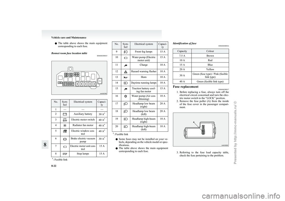
l
The table above shows the main equipment
corresponding to each fuse.
Bonnet room fuse location table E08404300015No. Sym-
bol Electrical system Capaci-
ty
1 — ——
2 Auxiliary battery
30 A*
3 Electric motor switch
40 A*
4 Radiator fan motor
40 A*
5 Electric window con-
trol 40 A
*
6 Brake electric vacuum
pump 30 A
*
7 Electric motor unit con-
trol 15 A
8 Stop lamps 15 A
* : Fusible link No. Sym-
bol Electrical system Capaci-
ty
9 Front fog lamps 15 A
10 Water pump (Electric
motor unit) 15 A
11 Charge 10 A
12 Hazard warning flasher 10 A
13 Horn 10 A
14 Daytime running lamps 10 A
15 Traction battery cool-
ing fan motor 15 A
16 Water pump (Air con-
ditioning) 10 A
17 Headlamp low beam
(right) 20 A
18 Headlamp low beam
(left) 20 A
19 Headlamp high-beam
(right) 10 A
20 Headlamp high-beam
(left) 10 A
* : Fusible link l
Some
fuses may not be installed on your ve-
hicle, depending on the vehicle model or spec-
ifications.
l The table above shows the main equipment
corresponding to each fuse. Identification of fuse
E08404400016 Capacity Colour
7.5 A Brown
10 A Red
15 A Blue
20 A Yellow
30 A Green (fuse type) / Pink (fusible
link type)
40 A Green (fusible link type) Fuse replacement
E08404500017
1. Before
replacing a fuse, always turn off the
electrical circuit concerned and turn the elec-
tric motor switch to the “LOCK” position.
2. Remove the fuse puller (A) from the inside of the fuse cover in the passenger compart-
ment. 3. Referring
to the fuse load capacity table,
check the fuse pertaining to the problem. Vehicle care and Maintenance
8-22
8
Presented by http://mmc-manuals.ru/ \251
Page 162 of 193
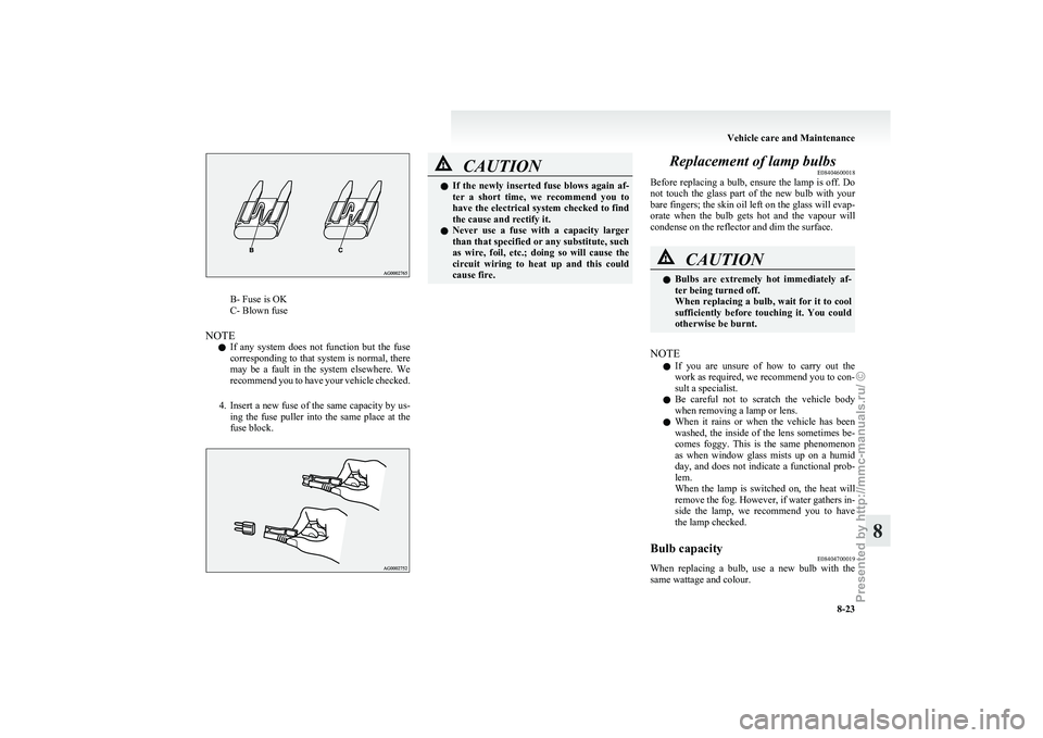
B- Fuse is OK
C- Blown fuse
NOTE l If
any system does not function but the fuse
corresponding to that system is normal, there
may be a fault in the system elsewhere. We
recommend you to have your vehicle checked.
4. Insert a new fuse of the same capacity by us- ing the fuse puller into the same place at the
fuse block. CAUTION
l
If
the newly inserted fuse blows again af-
ter a short time, we recommend you to
have the electrical system checked to find
the cause and rectify it.
l Never use a fuse with a capacity larger
than that specified or any substitute, such
as wire, foil, etc.; doing so will cause the
circuit wiring to heat up and this could
cause fire. Replacement of lamp bulbs
E08404600018
Before
replacing a bulb, ensure the lamp is off. Do
not touch the glass part of the new bulb with your
bare fingers; the skin oil left on the glass will evap-
orate when the bulb gets hot and the vapour will
condense on the reflector and dim the surface. CAUTION
l
Bulbs
are extremely hot immediately af-
ter being turned off.
When replacing a bulb, wait for it to cool
sufficiently before touching it. You could
otherwise be burnt.
NOTE l If
you are unsure of how to carry out the
work as required, we recommend you to con-
sult a specialist.
l Be careful not to scratch the vehicle body
when removing a lamp or lens.
l When it rains or when the vehicle has been
washed, the inside of the lens sometimes be-
comes foggy. This is the same phenomenon
as when window glass mists up on a humid
day, and does not indicate a functional prob-
lem.
When the lamp is switched on, the heat will
remove the fog. However, if water gathers in-
side the lamp, we recommend you to have
the lamp checked.
Bulb capacity E08404700019
When replacing a bulb, use a new bulb with the
same wattage and colour. Vehicle care and Maintenance
8-23 8
Presented by http://mmc-manuals.ru/ \251
Page 177 of 193
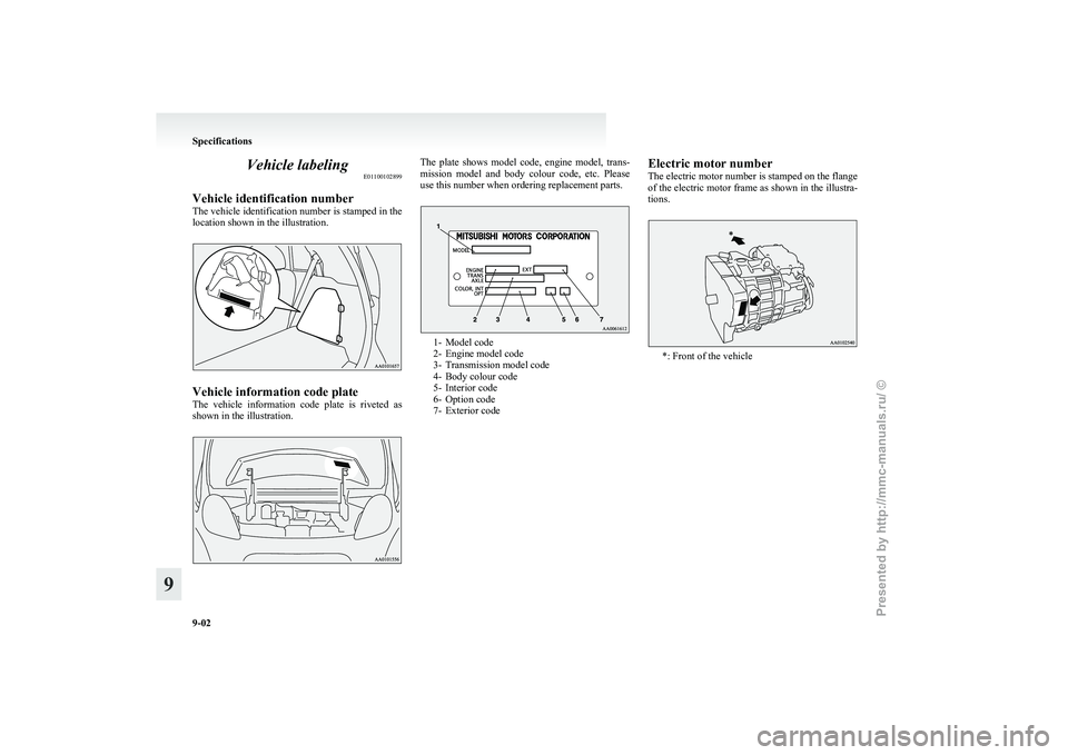
Vehicle labeling
E01100102899
Vehicle identification number
The
vehicle identification number is stamped in the
location shown in the illustration. Vehicle information code plate
The
vehicle information code plate is riveted as
shown in the illustration. The plate shows model code, engine model, trans-
mission
model and body colour code, etc. Please
use this number when ordering replacement parts. 1- Model code
2-
Engine model code
3- Transmission model code
4- Body colour code
5- Interior code
6- Option code
7- Exterior code Electric motor number
The electric motor number is stamped on the flange
of
the electric motor frame as shown in the illustra-
tions. *: Front of the vehicleSpecifications
9-02
9
Presented by http://mmc-manuals.ru/ \251