ESP MITSUBISHI I-MIEV 2011 Owners Manual
[x] Cancel search | Manufacturer: MITSUBISHI, Model Year: 2011, Model line: I-MIEV, Model: MITSUBISHI I-MIEV 2011Pages: 193, PDF Size: 12.2 MB
Page 14 of 193
l
Put the selector lever to the “B” (BRAKE) or
“C” (COMFORT) position according to the
road condition. To charge the traction battery
with appropriate use of regenerative braking
can increase the cruising range. Installation of accessories
E00200301003
We
recommend you to consult a MITSUBISHI
MOTORS Authorized Service Point.
l The installation of accessories, optional
parts, etc., should only be carried out within
the limits prescribed by law in your country,
and in accordance with the guidelines and
warnings contained within the documents ac-
companying this vehicle.
l Installing electric components incorrectly
could lead to a fire. See the “Modification/al-
terations to the electrical systems” section
within this owner’s manual.
l Using a cellular phone or radio set inside the
vehicle without an external antenna may
cause electrical system interference, which
could lead to unsafe vehicle operation.
l Tyres and wheels which do not meet specifi-
cations must not be used.
Refer to the “Specifications” section for in-
formation regarding wheel and tyre sizes.
Important points!
Due to large number of accessory and replacement
parts of different manufactures available in the mar-
ket, it is not possible, not only for MITSUBISHI
MOTORS, but also for a MITSUBISHI MOTORS
Authorized Service Point, to check whether the at-
tachment or installation of such parts affects the
overall safety of your MITSUBISHI-vehicle.
Even when such parts are officially authorized, for
example
by a “general operators permit” (an ap-
praisal for the part) or through the execution of the
part in an officially approved manner of construc-
tion, or when a single operation permit following
the attachment or installation of such parts, it can-
not be deduced from that alone, that the driving safe-
ty of your vehicle has not been affected.
Consider also that there basically exists no liability
on the part of the appraiser or the official. Maxi-
mum safety can only be ensured with parts recom-
mended, sold and fitted or installed by a
MITSUBISHI MOTORS authorized Service Point
(MITSUBISHI MOTORS genuine replacement
parts and MITSUBISHI MOTORS accessories).
The same also pertains to modifications of
MITSUBISHI vehicles with respect to the produc-
tion specifications. For safety reasons, do not at-
tempt any modifications other than those that fol-
low the recommendations of a MITSUBISHI
MOTORS authorized Service Point. General information
03
Presented by http://mmc-manuals.ru/ \251
Page 33 of 193
NOTE
l The
indication lamp (3) comes on each time
a switch is pressed.
l If the UNLOCK switch (2) is pressed and
any of the doors or the tailgate is not opened
within approximately 30 seconds, relocking
will automatically occur.
l It is possible to modify functions as follows:
For further information, please contact your
MITSUBISHI MOTORS Authorized Service
Point.
• The time for automatic relocking can bechanged.
• The confirmation function (flashing of the turn-signal lamps) can be set to oper-
ate only when the doors and the tailgate
are locked or only when the doors and
the tailgate are unlocked.
• The confirmation function (this indicates locking or unlocking of the doors and the
tailgate with the flash of the turn-signal
lamps) can be deactivated.
• The number of times the turn-signal lamps are flashed by the confirmation
function can be changed.
l The keyless entry system does not operate in
the following conditions:
• The key is left in the key cylinder.
• The door or the tailgate is open.
l The remote control switch will operate with-
in approximately 4 m from the vehicle. How-
ever, the operating range of the remote con-
trol switch may change if the vehicle is loca-
ted near a power station, or radio/TV broad-
casting station.
l If either of the following problems occurs,
the battery may be exhausted. • The remote control switch is operated at
the correct distance from the vehicle, but
the doors and the tailgate are not locked/
unlocked in response.
• The indication lamp (3) is dim or does not come on.
For further information, please contact
your MITSUBISHI MOTORS Author-
ized Service Point.
If you replace the battery yourself, refer
to “Procedure for replacing the remote
control switch battery” on page 2-04.
l If your remote control switch is lost or dam-
aged, please contact your MITSUBISHI
MOTORS Authorized Service Point for a re-
placement remote control switch.
l If you wish to add a remote control switch,
we recommend you to contact a
MITSUBISHI MOTORS Authorized Service
Point.
A maximum of 4 remote control switches are
available for your vehicle.
Operation of the outside rear-view mir-
rors E00310800119
To fold
Within
30 seconds of locking the doors and the tail-
gate using the LOCK switch (1), press the LOCK
switch twice rapidly to fold the outside rear-view
mirrors.
To extend
Within 30 seconds of unlocking the doors and the
tailgate using the UNLOCK switch (2), press the
UNLOCK switch twice rapidly to return the out-
side rear-view mirrors to their extended positions. Procedure for replacing the remote
control switch battery
E00309500129
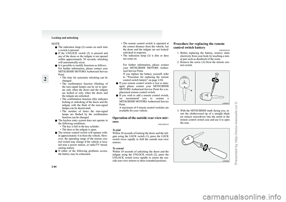
1. Before
replacing the battery, remove static
electricity from your body by touching a met-
al part such as doorknob of the room.
2. Remove the screw (A) from the remote con- trol switch. 3. With
the MITSUBISHI mark facing you, in-
sert the clothcovered tip of a straight blade
(or minus) screwdriver into the notch in the
remote control switch case and use it to open
the case. Locking and unlocking
2-04
2
Presented by http://mmc-manuals.ru/ \251
Page 38 of 193
Electric window control
E00302200550
The electric windows can only be operated with the
electric motor switch in the “ON” position. WARNING
l Before operating the electric window con-
trol, make sure that nothing can get trap-
ped (head, hand, finger, etc.).
l Never leave the vehicle without removing
the key.
l Never leave a child (or other person who
might not be capable of safe operation of
the electric window control) in the vehicle
alone.
l The child may tamper with the switch at
the risk of its hands or head being trap-
ped in the window.
Electric window control switch E00302301705
Each window opens or closes while the correspond-
ing switch is operated.
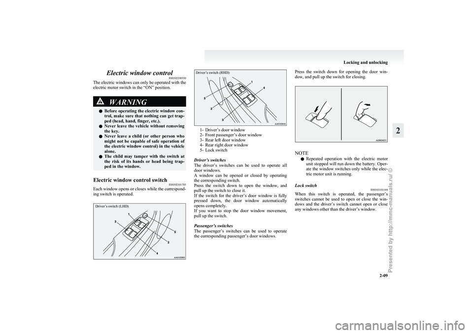
Driver’s switch (LHD)
Driver’s switch (RHD) 1- Driver’s door window
2-
Front passenger’s door window
3- Rear left door window
4- Rear right door window
5- Lock switch
Driver’s switches
The driver’s switches can be used to operate all
door windows.
A window can be opened or closed by operating
the corresponding switch.
Press the switch down to open the window, and
pull up the switch to close it.
If the switch for the driver’s door window is fully
pressed down, the door window automatically
opens completely.
If you want to stop the door window movement,
pull up the switch.
Passenger’s switches
The passenger’s switches can be used to operate
the corresponding passenger’s door windows. Press the switch down for opening the door win-
dow, and pull up the switch for closing.
NOTE
l Repeated
operation with the electric motor
unit stopped will run down the battery. Oper-
ate the window switches only while the elec-
tric motor unit is running.
Lock switch E00303101188
When this switch is operated, the passenger’s
switches
cannot be used to open or close the win-
dows and the driver’s switch cannot open or close
any windows other than the driver’s window. Locking and unlocking
2-09 2
Presented by http://mmc-manuals.ru/ \251
Page 46 of 193
Head restraints
E00403301497WARNING
l Driving without the head restraints in
place can cause you and your passengers
serious injury or death in an accident. To
reduce the risk of injury in an accident, al-
ways make sure the head restraints are in-
stalled and properly positioned when the
seat is occupied.
l Never place a cushion or similar device
on the seatback. This can adversely affect
head restraint performance by increasing
the distance between your head and the
restraint.
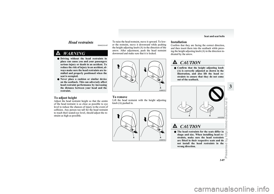
To adjust height
Adjust
the head restraint height so that the centre
of the head restraint is as close as possible to eye
level to reduce the chances of injury in the event of
collision. Any person too tall for the head restraint
to reach their seated eye level, should adjust the re-
straint as high as possible. To raise the head restraint, move it upward. To low-
er
the restraint, move it downward while pushing
the height adjusting knob (A) in the direction of the
arrow. After adjustment, push the head restraint
downward and make sure that it is locked. To remove
Lift
the head restraint with the height adjusting
knob (A) pushed in. Installation
Confirm
that they are facing the correct direction,
and then insert them into the seatback while press-
ing the height adjusting knob (A) in the direction in-
dicated by the arrow. CAUTION
l
Confirm
that the height adjusting knob
(A) is correctly adjusted as shown in the
illustration, and also lift the head re-
straints to ensure that they do not come
out of the seatback. CAUTION
l
The
head restraints for the seats differ in
shape and size. When installing head re-
straints, make sure the head restraints
are fitted in their respective seats and do
not install the head restraints in the
wrong direction. Seat and seat belts
3-07 3
Presented by http://mmc-manuals.ru/ \251
Page 47 of 193
Seat belts
E00404800636
To
protect you and your passengers in the event of
an accident, it is most important that the seat belts
be worn correctly while driving.
The front seat belts have a pretensioner system.
These belts are used the same way as a convention-
al seat belt.
Refer to “Seat belt pretensioner system and force
limiter system” on page 3-11 WARNING
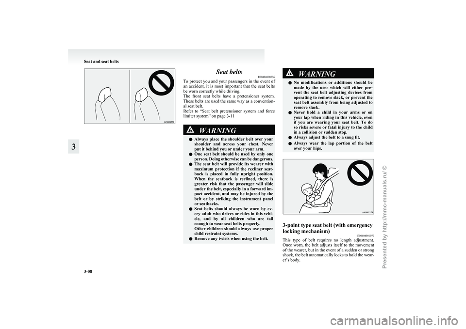
l Always
place the shoulder belt over your
shoulder and across your chest. Never
put it behind you or under your arm.
l One seat belt should be used by only one
person. Doing otherwise can be dangerous.
l The seat belt will provide its wearer with
maximum protection if the recliner seat-
back is placed in fully upright position.
When the seatback is reclined, there is
greater risk that the passenger will slide
under the belt, especially in a forward im-
pact accident, and may be injured by the
belt or by striking the instrument panel
or seatbacks.
l Seat belts should always be worn by ev-
ery adult who drives or rides in this vehi-
cle, and by all children who are tall
enough to wear seat belts properly.
Other children should always use proper
child restraint systems.
l Remove any twists when using the belt. WARNING
l No
modifications or additions should be
made by the user which will either pre-
vent the seat belt adjusting devices from
operating to remove slack, or prevent the
seat belt assembly from being adjusted to
remove slack.
l Never hold a child in your arms or on
your lap when riding in this vehicle, even
if you are wearing your seat belt. To do
so risks severe or fatal injury to the child
in a collision or sudden stop.
l Always adjust the belt to a snug fit.
l Always wear the lap portion of the belt
over your hips. 3-point type seat belt (with emergency
locking mechanism)
E00404901070
This type of belt requires no length adjustment.
Once
worn, the belt adjusts itself to the movement
of the wearer, but in the event of a sudden or strong
shock, the belt automatically locks to hold the wear-
er’s body. Seat and seat belts
3-08
3
Presented by http://mmc-manuals.ru/ \251
Page 50 of 193
Seat belt pretensioner system and
force limiter system E00405700166
The
driver’s seat and front passenger’s seat each
have a seat belt equipped with a pretensioner system.
Pretensioner system E00405801164
The pretensioner system will retract its respective
seat
belts instantaneously, thus maximizing the seat
belt’s effectiveness, if there is a frontal impact se-
vere enough to injure the driver and/or front passen-
ger and the electric motor switch is in the “ON” or
“START” position. WARNING
l To
obtain the best results from your pre-
tensioner seat belt, make sure you have ad-
justed your seat correctly and wear your
seat belt properly. CAUTION
l
Installation
of audio equipment or re-
pairs in the vicinity of the pretensioner
seat belts or floor console must be per-
formed in line with MITSUBISHI
MOTORS guidelines. It is important to
do so because the work could affect the
pretensioner systems. CAUTION
l
If
you need to scrap the vehicle, please con-
sult a MITSUBISHI MOTORS Author-
ized Service Point. It is important to do
so because unexpected activation of the
pretensioner seat belts could cause inju-
ries.
NOTE l The
pretensioner seat belts will be activated
if the vehicle suffers a severe frontal impact,
even if the seat belts are not worn.
l The pretensioner seat belts are designed to
work only once. After the pretensioner seat
belts have been activated, we recommend
you have them replaced by a MITSUBISHI
MOTORS Authorized Service Point.
SRS warning lamp E00405900315
This warning lamp is shared by the SRS airbags
and
the pretensioner seat belts. Refer to “SRS warn-
ing lamp” on page 3-29.
Force limiter system E00406000209
In the event of a collision, each force limiter sys-
tem
will effectively absorb the load applied to the
seat belt to minimize the impact to the passenger. Child restraint
E00406401747
When
transporting children in your vehicle, some
type of child restraint system should always be
used according to the size of the child. This is re-
quired by law in most countries.
The regulations concerning driving with children in
the front seat may differ from country to country.
You are advised to comply with the relevant regula-
tions. WARNING
l When
possible, put children in the rear
seat. Accident statistics indicate that chil-
dren of all sizes and ages are safer when
properly restrained in the rear seat rath-
er than in the front seat.
l Holding a child in your arms is no substi-
tute for a restraint system. Failure to use
a proper restraint system can result in se-
vere or fatal injury to the child.
l Each child restraint device or fixing is to
be used only by one child. Seat and seat belts
3-11 3
Presented by http://mmc-manuals.ru/ \251
Page 60 of 193
How the Supplemental Restraint Sys-
tem works
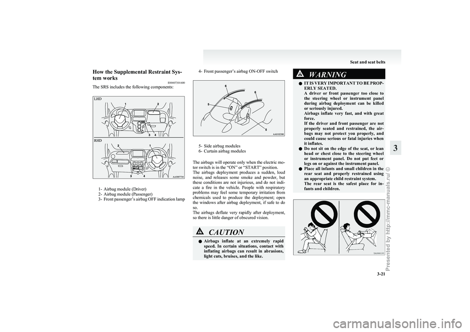
E00407301600
The SRS includes the following components: 1- Airbag module (Driver)
2-
Airbag module (Passenger)
3- Front passenger’s airbag OFF indication lamp 4- Front passenger’s airbag ON-OFF switch 5- Side airbag modules
6-
Curtain airbag modules
The airbags will operate only when the electric mo-
tor switch is in the “ON” or “START” position.
The airbags deployment produces a sudden, loud
noise, and releases some smoke and powder, but
these conditions are not injurious, and do not indi-
cate a fire in the vehicle. People with respiratory
problems may feel some temporary irritation from
chemicals used to produce the deployment; open
the windows after airbag deployment, if safe to do
so.
The airbags deflate very rapidly after deployment,
so there is little danger of obscured vision. CAUTION
l
Airbags
inflate at an extremely rapid
speed. In certain situations, contact with
inflating airbags can result in abrasions,
light cuts, bruises, and the like. WARNING
l IT
IS VERY IMPORTANT TO BE PROP-
ERLY SEATED.
A driver or front passenger too close to
the steering wheel or instrument panel
during airbag deployment can be killed
or seriously injured.
Airbags inflate very fast, and with great
force.
If the driver and front passenger are not
properly seated and restrained, the air-
bags may not protect you properly, and
could cause serious or fatal injuries when
it inflates.
l Do not sit on the edge of the seat, or lean
head or chest close to the steering wheel
or instrument panel. Do not put feet or
legs on or against the instrument panel.
l Place all infants and small children in the
rear seat and properly restrained using
an appropriate child restraint system.
The rear seat is the safest place for in-
fants and children. Seat and seat belts
3-21 3
Presented by http://mmc-manuals.ru/ \251
Page 64 of 193
Deployment of front airbags
E00407501660
The front airbags ARE DESIGNED TO DEPLOY
when…
The
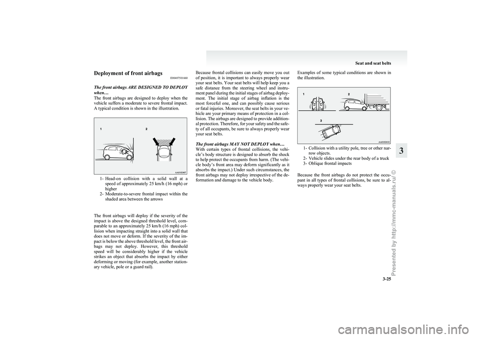
front airbags are designed to deploy when the
vehicle suffers a moderate to severe frontal impact.
A typical condition is shown in the illustration. 1- Head-on
collision with a solid wall at a
speed of approximately 25 km/h (16 mph) or
higher
2- Moderate-to-severe frontal impact within the shaded area between the arrows
The front airbags will deploy if the severity of the
impact is above the designed threshold level, com-
parable to an approximately 25 km/h (16 mph) col-
lision when impacting straight into a solid wall that
does not move or deform. If the severity of the im-
pact is below the above threshold level, the front air-
bags may not deploy. However, this threshold
speed will be considerably higher if the vehicle
strikes an object that absorbs the impact by either
deforming or moving (for example, another station-
ary vehicle, pole or a guard rail). Because frontal collisions can easily move you out
of
position, it is important to always properly wear
your seat belts. Your seat belts will help keep you a
safe distance from the steering wheel and instru-
ment panel during the initial stages of airbag deploy-
ment. The initial stage of airbag inflation is the
most forceful one, and can possibly cause serious
or fatal injuries. Moreover, the seat belts in your ve-
hicle are your primary means of protection in a col-
lision. The airbags are designed to provide addition-
al protection. Therefore, for your safety and the safe-
ty of all occupants, be sure to always properly wear
your seat belts.
The front airbags MAY NOT DEPLOY when…
With certain types of frontal collisions, the vehi-
cle’s body structure is designed to absorb the shock
to help protect the occupants from harm. (The vehi-
cle body’s front area may deform significantly as it
absorbs the impact.) Under such circumstances, the
front airbags may not deploy irrespective of the de-
formation and damage to the vehicle body. Examples of some typical conditions are shown in
the illustration. 1- Collision
with a utility pole, tree or other nar-
row objects.
2- Vehicle slides under the rear body of a truck
3- Oblique frontal impacts
Because the front airbags do not protect the occu-
pant in all types of frontal collisions, be sure to al-
ways properly wear your seat belts. Seat and seat belts
3-25 3
Presented by http://mmc-manuals.ru/ \251
Page 67 of 193
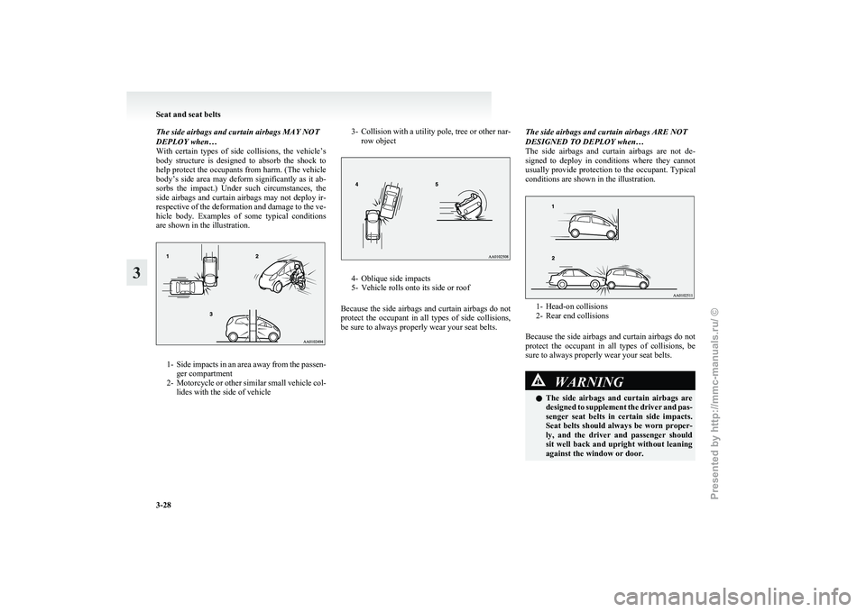
The side airbags and curtain airbags MAY NOT
DEPLOY when…
With
certain types of side collisions, the vehicle’s
body structure is designed to absorb the shock to
help protect the occupants from harm. (The vehicle
body’s side area may deform significantly as it ab-
sorbs the impact.) Under such circumstances, the
side airbags and curtain airbags may not deploy ir-
respective of the deformation and damage to the ve-
hicle body. Examples of some typical conditions
are shown in the illustration. 1- Side
impacts in an area away from the passen-
ger compartment
2- Motorcycle or other similar small vehicle col- lides with the side of vehicle 3- Collision
with a utility pole, tree or other nar-
row object 4- Oblique side impacts
5-
Vehicle rolls onto its side or roof
Because the side airbags and curtain airbags do not
protect the occupant in all types of side collisions,
be sure to always properly wear your seat belts. The side airbags and curtain airbags ARE NOT
DESIGNED TO DEPLOY when…
The
side airbags and curtain airbags are not de-
signed to deploy in conditions where they cannot
usually provide protection to the occupant. Typical
conditions are shown in the illustration. 1- Head-on collisions
2-
Rear end collisions
Because the side airbags and curtain airbags do not
protect the occupant in all types of collisions, be
sure to always properly wear your seat belts. WARNING
l The
side airbags and curtain airbags are
designed to supplement the driver and pas-
senger seat belts in certain side impacts.
Seat belts should always be worn proper-
ly, and the driver and passenger should
sit well back and upright without leaning
against the window or door. Seat and seat belts
3-28
3
Presented by http://mmc-manuals.ru/ \251
Page 74 of 193
switch is turned from the “LOCK” position
or the “ACC” position to the “ON” position.
3. When the vehicle is inspected at a
MITSUBISHI MOTORS Authorized Service
Point, the driving distance or number of
months remaining until the next inspection
will be shown.
NOTE l The indicated distance decreases in steps of
100 km (62 miles). The indicated number of
months decreases in steps of one month.
l It is possible to change the settings for the
service reminder.
For further information, we recommend you
to consult a MITSUBISHI MOTORS Author-
ized Service Point.
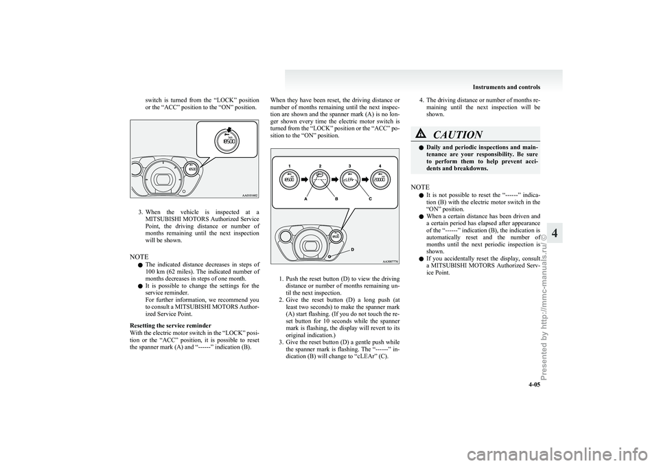
Resetting the service reminder
With the electric motor switch in the “LOCK” posi-
tion or the “ACC” position, it is possible to reset
the spanner mark (A) and “------” indication (B). When they have been reset, the driving distance or
number
of months remaining until the next inspec-
tion are shown and the spanner mark (A) is no lon-
ger shown every time the electric motor switch is
turned from the “LOCK” position or the “ACC” po-
sition to the “ON” position. 1. Push
the reset button (D) to view the driving
distance or number of months remaining un-
til the next inspection.
2. Give the reset button (D) a long push (at least two seconds) to make the spanner mark
(A) start flashing. (If you do not touch the re-
set button for 10 seconds while the spanner
mark is flashing, the display will revert to its
original indication.)
3. Give the reset button (D) a gentle push while the spanner mark is flashing. The “------” in-
dication (B) will change to “cLEAr” (C). 4. The
driving distance or number of months re-
maining until the next inspection will be
shown. CAUTION
l
Daily
and periodic inspections and main-
tenance are your responsibility. Be sure
to perform them to help prevent acci-
dents and breakdowns.
NOTE l It
is not possible to reset the “------” indica-
tion (B) with the electric motor switch in the
“ON” position.
l When a certain distance has been driven and
a certain period has elapsed after appearance
of the “------” indication (B), the indication is
automatically reset and the number of
months until the next periodic inspection is
shown.
l If you accidentally reset the display, consult
a MITSUBISHI MOTORS Authorized Serv-
ice Point. Instruments and controls
4-05 4
Presented by http://mmc-manuals.ru/ \251