battery location MITSUBISHI I-MIEV 2011 Owners Manual
[x] Cancel search | Manufacturer: MITSUBISHI, Model Year: 2011, Model line: I-MIEV, Model: MITSUBISHI I-MIEV 2011Pages: 193, PDF Size: 12.2 MB
Page 73 of 193
l
If there is no operation for about 10 seconds
when the meter illumination control or serv-
ice reminder is shown, the display returns to
the odometer.
Odometer E00530800016
The odometer indicates the total distance the vehi-
cle has travelled.
NOTE
l Even
if the electric motor switch is turned to
“ACC” or “LOCK”, the odometer will be dis-
played for about 30 seconds after the reset but-
ton is pressed.
Tripmeter E00530900017
The tripmeter indicates the distance travelled dur-
ing a particular trip or period.
There
are two tripmeter displays: Tripmeter and .
Tripmeter can be used to measure the distance
travelled
since the current trip began. At the same
time, Tripmeter can be used to measure the dis-
tance from an intermediate location.
NOTE
l Even
if the electric motor switch is turned to
the “ACC” or “LOCK” position, the tripme-
ter will be displayed for about 30 seconds af-
ter the reset button is pressed.
To reset the tripmeter
To return the display to “0”, press the reset button
(A) for more than 2 seconds. Only the currently dis-
played value will be reset. NOTE
l If
the auxiliary battery terminal is removed,
the memories for the tripmeter and
displays are erased and the displays return to
0.
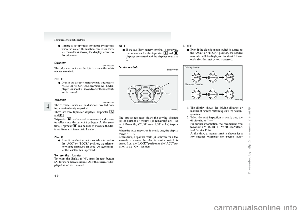
Service reminder E00517700164 The service reminder shows the driving distance
(1)
or number of months (2) remaining until the
next 12-monthly (20,000 km / 12,500 miles) inspec-
tion.
When the next inspection is nearly due, the display
shows “-----”.
At this time, a spanner mark (3) is shown for a few
seconds whenever the electric motor switch is
turned from the “LOCK” position or the “ACC” po-
sition to the “ON” position. NOTE
l Even
if the electric motor switch is turned to
the “ACC” or “LOCK” position, the service
reminder will be displayed for about 30 sec-
onds after the reset button is pressed.
Driving distance
Number of months 1. The
display shows the driving distance or
number of months remaining until the next in-
spection.
2. When the next inspection is nearly due, the display shows “-----”.
For further information, we recommend you
to consult a MITSUBISHI MOTORS Author-
ized Service Point.
At this time, a spanner mark is shown for a
few seconds whenever the electric motor Instruments and controls
4-04
4
Presented by http://mmc-manuals.ru/ \251
Page 79 of 193
NOTE
l Depressing
the brake pedal repeat-
edly may turn on the brake warn-
ing lamp and brake warning buz-
zer. It is normal if the lamp goes
out and the buzzer stops sounding
after a few seconds. CAUTION
l
In
the situations listed below,
brake performance may be com-
promised or the vehicle may be-
come unstable if brakes are ap-
plied suddenly; consequently,
avoid driving at high speeds or
applying the brakes suddenly.
Furthermore, the vehicle
should be brought to a stop in a
safe location and to have it
checked. • The brake warning lampdoes not illuminate when
the parking brake is applied
or does not turn off when
the parking brake is re-
leased.
• The brake warning lamp re- mains illuminated during
driving.
• The brake warning lamp and ABS warning lamp are
both illuminated at the
same time. Refer to “ABS
warning lamp” on page
5-14.
• The brake warning buzzer will not stop sounding. CAUTION
l
The
vehicle should be brought
to a halt in the following man-
ner when brake performance
has deteriorated. • Depress the brake pedalharder than usual.
Even if the brake pedal
moves down to the very end
of its possible stroke, keep it
pressed down hard.
• Should the brakes fail, use regenerative braking to re-
duce your speed and careful-
ly pull the parking brake lev-
er.
Depress the brake pedal to
operate the stop lamp to
alert the vehicles behind you.
NOTE l Operation
sounds of the brake elec-
tric vacuum pump may be heard
from the electric motor unit room
just after the electric motor switch
has been turned “ON” or when the
brake pedal is depressed.
This occurs when the brake elec-
tric vacuum pump is operating nor-
mally and does not indicate faulty
operation. Auxiliary battery charge warn-
ing lamp
E00502701219
This
warning lamp will illuminate when
there is a fault with the charging system
of the auxiliary battery.
Normally, when the electric motor
switch is turned to the “ON” position,
this warning lamp will illuminate. When
the electric motor unit is started, the
lamp goes out. CAUTION
l
If
it illuminates while the ready
indicator is illuminated, there is
a problem in the charging sys-
tem. In this case, immediately
park your vehicle in a safe
place and we recommend you
to have it checked. Door ajar warning lamp
E00503300840
This
lamp illuminates when either of the
doors (also, the tailgate) is not complete-
ly closed.
If the vehicle speed exceeds about
8 km/h (5 mph) with a door ajar, the warn-
ing lamp will flash 16 times and, at the
same time, the buzzer will sound 16
times to notify the driver that a door is
ajar. Instruments and controls
4-10
4
Presented by http://mmc-manuals.ru/ \251
Page 128 of 193
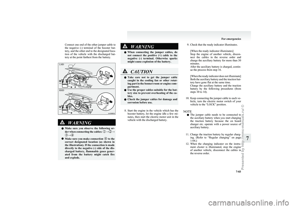
Connect one end of the other jumper cable to
the
negative (-) terminal of the booster bat-
tery, and the other end to the designated loca-
tion of the vehicle with the discharged bat-
tery at the point farthest from the battery. WARNING
l Make
sure you observe the following or-
der when connecting the cables: → →
→
l
Make sure you make connection to the
correct
designated location (as shown in
the illustration). If the connection is made
directly to the negative (-) side of the dis-
charged battery, flammable gases gener-
ated from the battery might catch fire
and explode. WARNING
l When
connecting the jumper cables, do
not connect the positive (+) cable to the
negative (-) terminal. Otherwise sparks
might cause explosion of the battery. CAUTION
l
Take
care not to get the jumper cable
caught in the cooling fan or other rotat-
ing part in the bonnet room or engine com-
partment.
l Use the proper cables suitable for the bat-
tery size to prevent overheating of the ca-
bles.
l Check the jumper cables for damage and
corrosion before use.
8. Start
the engine in the vehicle which has the booster battery, let the engine idle a few mi-
nutes, then start the electric motor unit in the
vehicle with the discharged battery.
9. Check that the ready indicator illuminates.
[When the ready indicator illuminates]
Stop
the engine of another vehicle, discon-
nect the cables in the reverse order and
charge the auxiliary battery for more than 30
minutes.
After the auxiliary battery is charged, contin-
ue the process from step 16.
[When the ready indicator does not illuminate]
Both the auxiliary battery and the traction bat-
tery have gone flat at the same time.
Charge the auxiliary battery and the traction
battery by the following procedures (from
steps 10 to 14).
10. Keep connecting the jumper cable to each ve- hicle, turn the electric motor switch of your
vehicle to the “LOCK” position.
NOTE l The jumper cable needs to be connected to
the auxiliary battery when you start charging
the traction battery because the on board
charger etc. operate with a power source of
auxiliary battery.
11. Charge the traction battery by regular charg- ing. (Refer to “Regular charging” on page
1-04.)
12. When the charging indicator on the instru- ment cluster is illuminated, stop the engine
of another vehicle, disconnect the cables in
the reverse order. For emergencies
7-03 7LHD
RH
D
Presented by http://mmc-manuals.ru/ \251
Page 129 of 193
NOTE
l When
the regular charging plug is connected
to the charging connection, the charging indi-
cator is blinking. When charging is started,
the charging indicator is illuminated.
l The auxiliary battery is automatically charg-
ed while charging the traction battery.
13. Charge the traction battery for more than 1 hour.
14. Disconnect the charging cable. (Refer to “Regular charging” on page 1-04.)
15. Turn the electric motor switch to the “START” position, make sure that the ready
indicator on the instrument cluster is illumi-
nated.
If the ready indicator does not illuminate, per-
form the procedure again from step 7.
If charging cannot be performed, consult a
MITSUBISHI MOTORS Authorized Service
Point.
16. Refit the battery cover. (Refer to “Auxiliary battery” on page 8-12.) WARNING
l Do
not charge the auxiliary battery using
an external battery charger while the aux-
iliary battery is mounted in the vehicle.
Doing so could cause the auxiliary bat-
tery to catch fire and explode and could
result in damage to the vehicle.
l Keep sparks, cigarettes, and flames away
from the auxiliary battery because the bat-
tery may produce an explosion.
l Use adequate ventilation when charging
or using the auxiliary battery in an en-
closed space.
l Remove all the caps before charging the
auxiliary battery.
l Electrolyte is corrosive diluted sulphuric
acid.
If electrolyte (battery acid) comes into con-
tact with your hands, eyes, clothes and
the painted surface of your vehicle, it
should be thoroughly flushed with water.
If electrolyte gets in your eyes, flush them
with water immediately and thoroughly,
and get prompt medical attention.
NOTE l If
the electric motor unit is started without
fully charging the auxiliary battery, it might
cause the anti-lock brake warning lamp to il-
luminate. Refer to “Anti-lock brake system
(ABS)” on page 5-14. Tyre repair kit
E00800901311
This
kit enables emergency repair of a small punc-
ture in the tread area of a tyre that has run over a
nail, screw, or similar object.
Storage
The tyre repair kit is stowed under the rear seat cush-
ion. The storage location of the tyre repair kit
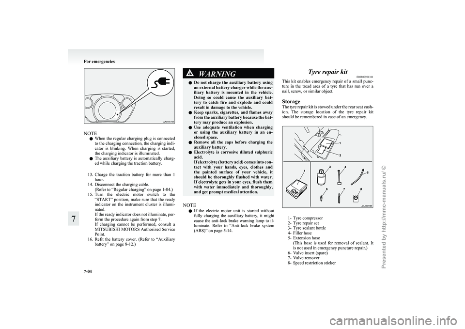
should be remembered in case of an emergency. 1- Tyre compressor
2-
Tyre repair set
3- Tyre sealant bottle
4- Filler hose
5- Extension hose (This hose is used for removal of sealant. It
is not used in emergency puncture repair.)
6- Valve insert (spare)
7- Valve remover
8- Speed restriction sticker For emergencies
7-04
7
Presented by http://mmc-manuals.ru/ \251
Page 160 of 193
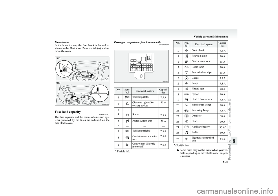
Bonnet room
In
the bonnet room, the fuse block is located as
shown in the illustration. Press the tab (A) and re-
move the cover. Fuse load capacity
E08404100013
The fuse capacity and the names of electrical sys-
tems
protected by the fuses are indicated on the
fuse block cover. Passenger compartment fuse location table
E08404200014 No. Sym-
bol Electrical system Capaci-
ties
1 Tail lamp (left)
7.5 A
2 Cigarette lighter/Ac-
cessory socket
15 A
3 — ——
4 Starter
7.5 A
5 Audio system amp
20 A
6 — ——
7 Tail lamp (right)
7.5 A
8 Outside rear-view mir-
rors
7.5 A
9 Control unit (Electric
motor unit)
7.5 A
* : Fusible link No. Sym-
bol Electrical system Capaci-
ties
10 Control unit
7.5 A
11 Rear fog lamp
10 A
12 Central door lock
15 A
13 Room lamp
10 A
14 Rear window wiper
15 A
15 Gauge
7.5 A
16 Relay
7.5 A
17 Heated seat
20 A
18 Option
10 A
19 Heated door mirror
7.5 A
20 Windscreen wiper
20 A
21 Reversing lamps
7.5 A
22 Demister
30 A
23 Heater
30 A
24 Auxiliary battery
30 A*
25 Radio
10 A
26 Electronic controlled
unit
15 A
* : Fusible link l
Some
fuses may not be installed on your ve-
hicle, depending on the vehicle model or spec-
ifications. Vehicle care and Maintenance
8-21 8
Presented by http://mmc-manuals.ru/ \251
Page 161 of 193
l
The table above shows the main equipment
corresponding to each fuse.
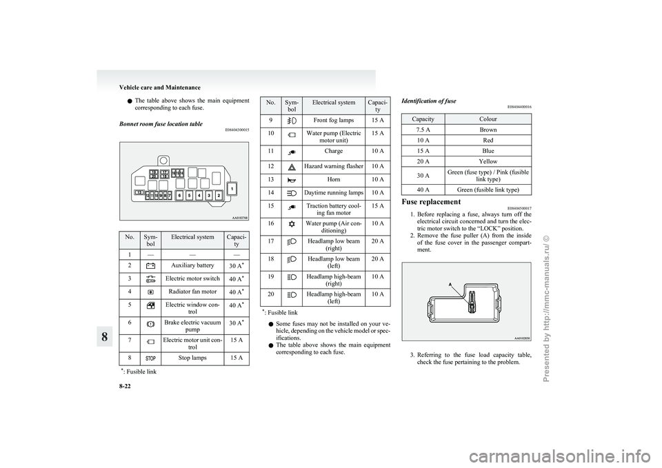
Bonnet room fuse location table E08404300015No. Sym-
bol Electrical system Capaci-
ty
1 — ——
2 Auxiliary battery
30 A*
3 Electric motor switch
40 A*
4 Radiator fan motor
40 A*
5 Electric window con-
trol 40 A
*
6 Brake electric vacuum
pump 30 A
*
7 Electric motor unit con-
trol 15 A
8 Stop lamps 15 A
* : Fusible link No. Sym-
bol Electrical system Capaci-
ty
9 Front fog lamps 15 A
10 Water pump (Electric
motor unit) 15 A
11 Charge 10 A
12 Hazard warning flasher 10 A
13 Horn 10 A
14 Daytime running lamps 10 A
15 Traction battery cool-
ing fan motor 15 A
16 Water pump (Air con-
ditioning) 10 A
17 Headlamp low beam
(right) 20 A
18 Headlamp low beam
(left) 20 A
19 Headlamp high-beam
(right) 10 A
20 Headlamp high-beam
(left) 10 A
* : Fusible link l
Some
fuses may not be installed on your ve-
hicle, depending on the vehicle model or spec-
ifications.
l The table above shows the main equipment
corresponding to each fuse. Identification of fuse
E08404400016 Capacity Colour
7.5 A Brown
10 A Red
15 A Blue
20 A Yellow
30 A Green (fuse type) / Pink (fusible
link type)
40 A Green (fusible link type) Fuse replacement
E08404500017
1. Before
replacing a fuse, always turn off the
electrical circuit concerned and turn the elec-
tric motor switch to the “LOCK” position.
2. Remove the fuse puller (A) from the inside of the fuse cover in the passenger compart-
ment. 3. Referring
to the fuse load capacity table,
check the fuse pertaining to the problem. Vehicle care and Maintenance
8-22
8
Presented by http://mmc-manuals.ru/ \251