radio MITSUBISHI I-MIEV 2011 Owners Manual
[x] Cancel search | Manufacturer: MITSUBISHI, Model Year: 2011, Model line: I-MIEV, Model: MITSUBISHI I-MIEV 2011Pages: 193, PDF Size: 12.2 MB
Page 14 of 193

l
Put the selector lever to the “B” (BRAKE) or
“C” (COMFORT) position according to the
road condition. To charge the traction battery
with appropriate use of regenerative braking
can increase the cruising range. Installation of accessories
E00200301003
We
recommend you to consult a MITSUBISHI
MOTORS Authorized Service Point.
l The installation of accessories, optional
parts, etc., should only be carried out within
the limits prescribed by law in your country,
and in accordance with the guidelines and
warnings contained within the documents ac-
companying this vehicle.
l Installing electric components incorrectly
could lead to a fire. See the “Modification/al-
terations to the electrical systems” section
within this owner’s manual.
l Using a cellular phone or radio set inside the
vehicle without an external antenna may
cause electrical system interference, which
could lead to unsafe vehicle operation.
l Tyres and wheels which do not meet specifi-
cations must not be used.
Refer to the “Specifications” section for in-
formation regarding wheel and tyre sizes.
Important points!
Due to large number of accessory and replacement
parts of different manufactures available in the mar-
ket, it is not possible, not only for MITSUBISHI
MOTORS, but also for a MITSUBISHI MOTORS
Authorized Service Point, to check whether the at-
tachment or installation of such parts affects the
overall safety of your MITSUBISHI-vehicle.
Even when such parts are officially authorized, for
example
by a “general operators permit” (an ap-
praisal for the part) or through the execution of the
part in an officially approved manner of construc-
tion, or when a single operation permit following
the attachment or installation of such parts, it can-
not be deduced from that alone, that the driving safe-
ty of your vehicle has not been affected.
Consider also that there basically exists no liability
on the part of the appraiser or the official. Maxi-
mum safety can only be ensured with parts recom-
mended, sold and fitted or installed by a
MITSUBISHI MOTORS authorized Service Point
(MITSUBISHI MOTORS genuine replacement
parts and MITSUBISHI MOTORS accessories).
The same also pertains to modifications of
MITSUBISHI vehicles with respect to the produc-
tion specifications. For safety reasons, do not at-
tempt any modifications other than those that fol-
low the recommendations of a MITSUBISHI
MOTORS authorized Service Point. General information
03
Presented by http://mmc-manuals.ru/ \251
Page 33 of 193

NOTE
l The
indication lamp (3) comes on each time
a switch is pressed.
l If the UNLOCK switch (2) is pressed and
any of the doors or the tailgate is not opened
within approximately 30 seconds, relocking
will automatically occur.
l It is possible to modify functions as follows:
For further information, please contact your
MITSUBISHI MOTORS Authorized Service
Point.
• The time for automatic relocking can bechanged.
• The confirmation function (flashing of the turn-signal lamps) can be set to oper-
ate only when the doors and the tailgate
are locked or only when the doors and
the tailgate are unlocked.
• The confirmation function (this indicates locking or unlocking of the doors and the
tailgate with the flash of the turn-signal
lamps) can be deactivated.
• The number of times the turn-signal lamps are flashed by the confirmation
function can be changed.
l The keyless entry system does not operate in
the following conditions:
• The key is left in the key cylinder.
• The door or the tailgate is open.
l The remote control switch will operate with-
in approximately 4 m from the vehicle. How-
ever, the operating range of the remote con-
trol switch may change if the vehicle is loca-
ted near a power station, or radio/TV broad-
casting station.
l If either of the following problems occurs,
the battery may be exhausted. • The remote control switch is operated at
the correct distance from the vehicle, but
the doors and the tailgate are not locked/
unlocked in response.
• The indication lamp (3) is dim or does not come on.
For further information, please contact
your MITSUBISHI MOTORS Author-
ized Service Point.
If you replace the battery yourself, refer
to “Procedure for replacing the remote
control switch battery” on page 2-04.
l If your remote control switch is lost or dam-
aged, please contact your MITSUBISHI
MOTORS Authorized Service Point for a re-
placement remote control switch.
l If you wish to add a remote control switch,
we recommend you to contact a
MITSUBISHI MOTORS Authorized Service
Point.
A maximum of 4 remote control switches are
available for your vehicle.
Operation of the outside rear-view mir-
rors E00310800119
To fold
Within
30 seconds of locking the doors and the tail-
gate using the LOCK switch (1), press the LOCK
switch twice rapidly to fold the outside rear-view
mirrors.
To extend
Within 30 seconds of unlocking the doors and the
tailgate using the UNLOCK switch (2), press the
UNLOCK switch twice rapidly to return the out-
side rear-view mirrors to their extended positions. Procedure for replacing the remote
control switch battery
E00309500129
1. Before
replacing the battery, remove static
electricity from your body by touching a met-
al part such as doorknob of the room.
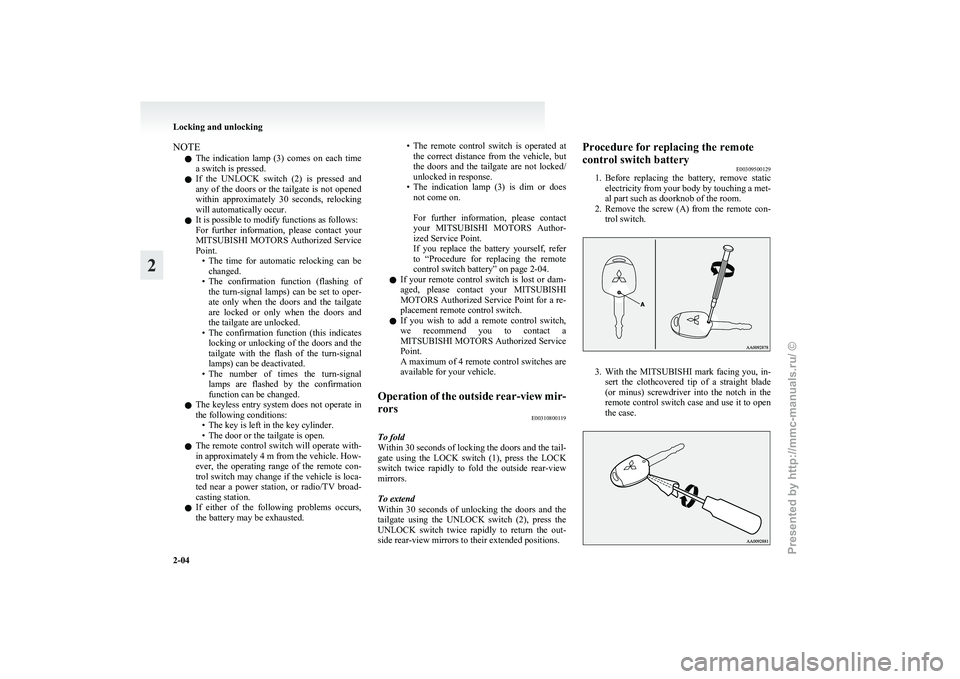
2. Remove the screw (A) from the remote con- trol switch. 3. With
the MITSUBISHI mark facing you, in-
sert the clothcovered tip of a straight blade
(or minus) screwdriver into the notch in the
remote control switch case and use it to open
the case. Locking and unlocking
2-04
2
Presented by http://mmc-manuals.ru/ \251
Page 119 of 193

Antenna
E00710500673
When
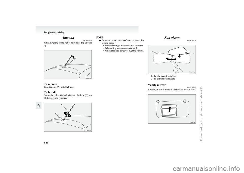
listening to the radio, fully raise the antenna
up. To remove
Turn the pole (A) anticlockwise.
To install
Screw
the pole (A) clockwise into the base (B) un-
til it is securely retained. NOTE
l Be
sure to remove the roof antenna in the fol-
lowing cases: • When entering a place with low clearance.
• When using an automatic car wash.
• When placing a car cover over the vehicle. Sun visors
E00711201179 1- To eliminate front glare
2-
To eliminate side glare
Vanity mirror E00731900247
A vanity mirror is fitted to the back of the sun visor. For pleasant driving
6-10
6
Presented by http://mmc-manuals.ru/ \251
Page 160 of 193

Bonnet room
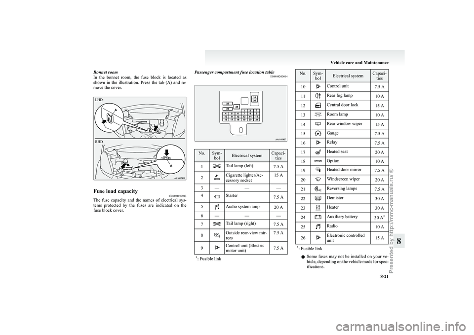
In
the bonnet room, the fuse block is located as
shown in the illustration. Press the tab (A) and re-
move the cover. Fuse load capacity
E08404100013
The fuse capacity and the names of electrical sys-
tems
protected by the fuses are indicated on the
fuse block cover. Passenger compartment fuse location table
E08404200014 No. Sym-
bol Electrical system Capaci-
ties
1 Tail lamp (left)
7.5 A
2 Cigarette lighter/Ac-
cessory socket
15 A
3 — ——
4 Starter
7.5 A
5 Audio system amp
20 A
6 — ——
7 Tail lamp (right)
7.5 A
8 Outside rear-view mir-
rors
7.5 A
9 Control unit (Electric
motor unit)
7.5 A
* : Fusible link No. Sym-
bol Electrical system Capaci-
ties
10 Control unit
7.5 A
11 Rear fog lamp
10 A
12 Central door lock
15 A
13 Room lamp
10 A
14 Rear window wiper
15 A
15 Gauge
7.5 A
16 Relay
7.5 A
17 Heated seat
20 A
18 Option
10 A
19 Heated door mirror
7.5 A
20 Windscreen wiper
20 A
21 Reversing lamps
7.5 A
22 Demister
30 A
23 Heater
30 A
24 Auxiliary battery
30 A*
25 Radio
10 A
26 Electronic controlled
unit
15 A
* : Fusible link l
Some
fuses may not be installed on your ve-
hicle, depending on the vehicle model or spec-
ifications. Vehicle care and Maintenance
8-21 8
Presented by http://mmc-manuals.ru/ \251