clock MITSUBISHI iMiEV 2013 (in English) User Guide
[x] Cancel search | Manufacturer: MITSUBISHI, Model Year: 2013, Model line: iMiEV, Model: MITSUBISHI iMiEV 2013Pages: 258, PDF Size: 13 MB
Page 173 of 258
Digital clock*
E00711800527
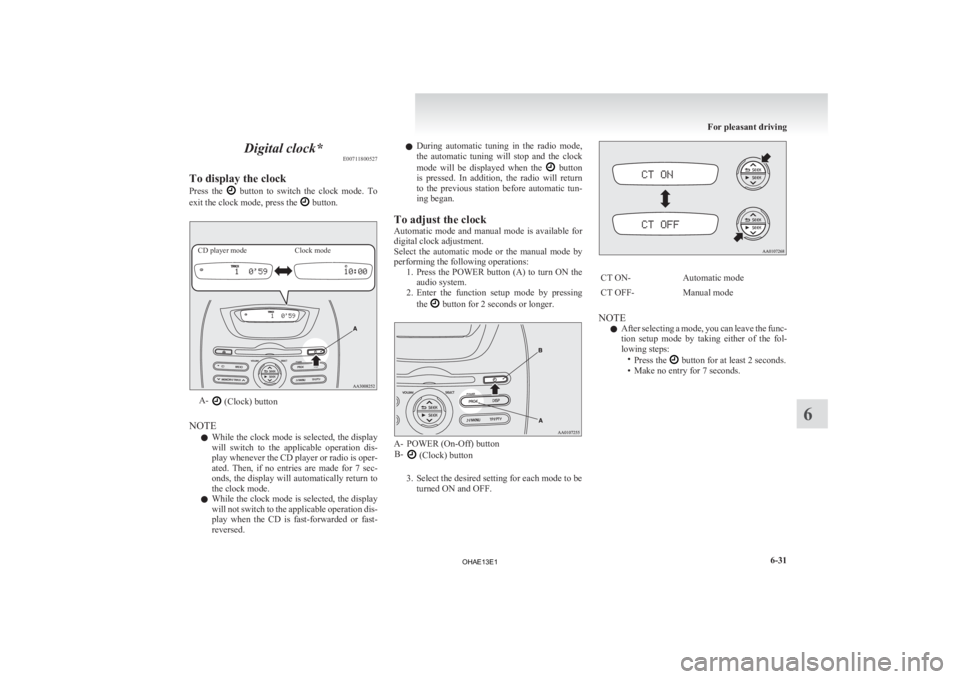
To display the clock
Press
the button to switch the clock mode. To
exit the clock mode, press the button.
CD player mode
Clock modeA-
(Clock) button
NOTE l While
the clock mode is selected, the display
will switch to the applicable operation dis-
play whenever the CD player or radio is oper-
ated. Then, if no entries are made for 7 sec-
onds, the display will automatically return to
the clock mode.
l While the clock mode is selected, the display
will not switch to the applicable operation dis-
play when the CD is fast-forwarded or fast-
reversed. l
During
automatic tuning in the radio mode,
the automatic tuning will stop and the clock
mode will be displayed when the button
is
pressed. In addition, the radio will return
to the previous station before automatic tun-
ing began.
To adjust the clock
Automatic mode and manual mode is available for
digital clock adjustment.
Select the automatic mode or the manual mode by
performing the following operations: 1. Press the POWER button (A) to turn ON theaudio system.
2. Enter the function setup mode by pressing
the button for 2 seconds or longer.
A- POWER (On-Off) button
B- (Clock) button
3.
Select the desired setting for each mode to be turned ON and OFF. CT ON-
Automatic mode
CT OFF- Manual mode
NOTE l After
selecting a mode, you can leave the func-
tion setup mode by taking either of the fol-
lowing steps: •Press the button for at least 2 seconds.
•
Make no entry for 7 seconds. For pleasant driving
6-31 6
OHAE13E1
Page 174 of 258
Automatic mode
The
automatic adjustment mode can set the local
time automatically by using the signal from local
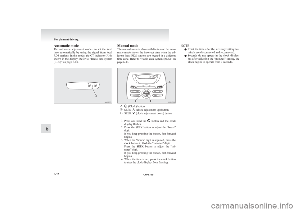
RDS stations. In this mode, the CT indicator (A) is
shown in the display. Refer to “Radio data system
(RDS)” on page 6-13. Manual mode
The
manual mode is also available in case the auto-
matic mode shows the incorrect time when the ad-
jacent local RDS stations are located in a different
time zone. Refer to “Radio data system (RDS)” on
page 6-13. A-
(Clock) button
B- SEEK (clock adjustment up) button
C- SEEK (clock adjustment down) button
1. Press
and hold the button and the clock
display flashes.
2. Press
the SEEK button to adjust the “hours”
digit.
If you keep pressing the button, fast-forward
begins.
3. When the “hours” digit is adjusted, press the clock button to flash the “minutes” digit.
Press the SEEK button to adjust the “mi-
nutes” digit.
If you keep pressing the button, fast-forward
begins.
4. When the time is set, press the clock button to stop the clock display from flashing. NOTE
l Reset
the time after the auxiliary battery ter-
minals are disconnected and reconnected.
l Seconds do not appear in the clock display,
but after adjusting the “minutes” setting, the
clock begins to operate from 0 seconds. For pleasant driving
6-32
6
OHAE13E1
Page 190 of 258
l
Use the tyre sealant only at ambient tempera-
tures of -30 °C to + 60 °C.
l Effect an emergency repair without pulling
out the object (nail, screw, etc.) that is stuck
in the tyre.
l Do not use the tyre sealant if the tyre has
been damaged by being driven when insuffi-
ciently inflated (e.g. bumps, cuts, cracks etc.
on the tyre).
l Wipe tyre sealant off the paintwork immedi-
ately with a damp cloth.
l Immediately wash clothes contaminated with
tyre sealant.
Before repairing a tyre, first stop your vehicle in a
safe, flat location. 1. Park the vehicle on level and stable ground.
2. Set the parking brake firmly.
3. Move the selector lever to the “P” (PARK)position and turn the electric motor switch to
the “LOCK” position.
4. Turn on the hazard warning flashers and set up a warning triangle, flashing signal lamp,
etc., at an adequate distance from the vehi-
cle, and have all your passengers leave the ve-
hicle.
5. Take out the tyre repair kit.
6. Shake the tyre sealant bottle well. NOTE
l In
cold conditions (when the ambient temper-
ature is 0 °C or lower), thickening of the tyre
sealant can make the tyre sealant hard to
squeeze out of the bottle. Warm the bottle in-
side the vehicle.
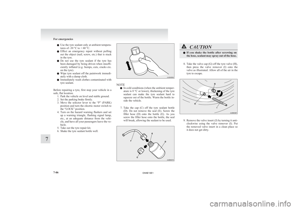
7. Take the cap (C) off the tyre sealant bottle (D). Do not remove the seal (E). Screw the
filler hose (D) onto the bottle (E). As you
screw the filler hose onto the bottle, the seal
will break, allowing the sealant to be used. CAUTION
l
If
you shake the bottle after screwing on
the hose, sealant may spray out of the hose.
8. Take the valve cap (G) off the tyre valve (H), then
press the valve remover (I) onto the
valve as illustrated. Allow all of the air in the
tyre to escape. 9. Remove
the valve insert (J) by turning it anti-
clockwise using the valve remover (I). Put
the removed valve insert in a clean place so
it does not get dirty. For emergencies
7-06
7
OHAE13E1
Page 207 of 258
CAUTION
l
Be careful that hands or fingers are not
trapped when closing the bonnet.
l Before driving, make sure that the bon-
net is securely locked. An incompletely
locked bonnet can suddenly open while
driving. This can be extremely dangerous. Coolant/Hot water heater fluid
E08402100048
To check the coolant level
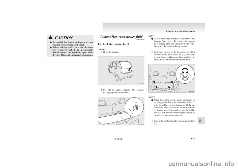
Coolant 1.
Open the tailgate. 2. Peel
off the Velcro fastener (A) to remove
the luggage floor carpet (B). NOTE
l A
heat insulating material is attached to the
luggage floor carpet. To remove the luggage
floor carpet, grab and lift up both the carpet
fabric and the heat insulating material.
3. Turn the 4 screws on the front and rear of the electric motor unit room lid (C) anticlock-
wise to loosen and remove them, and then re-
move the electric motor unit room lid (C). NOTE
l When
laying the electric motor unit room lid
on the ground, leave the underside of the lid
with the rubber surface facing up. If the un-
derside is facing downward rubbish and oth-
er foreign material could get on the rubber
surface and prevent proper reinstallation of
the electric motor unit room lid.
4. Check the coolant level in the reservoir tank (D). Vehicle care and Maintenance
8-09 8
OHAE13E1
Page 210 of 258
The brake fluid in the master cylinder should be
checked
when doing other work under the bonnet.
The brake system should also be checked for leak-
age at the same time.
If the brake fluid level falls markedly in a short
length of time, it indicates leaks from the brake sys-
tem.
If this occurs, we recommend you to have the vehi-
cle checked.
Fluid type
Use brake fluid conforming to DOT3 or DOT4
from a sealed container. The brake fluid is hygro-
scopic. Too much moisture in the brake fluid will
adversely affect the brake system, reducing the per-
formance. CAUTION
l
Take
care in handling brake fluid as it is
harmful to the eyes, may irritate your
skin and also damage painted surfaces.
l Use only the specified brake fluid.
Do not mix or add different brands of
brake fluid to prevent chemical reactions.
Do not let any petroleum-based fluid
touch, mix with, or get into the brake fluid.
This will damage the seals.
l Keep the reservoir tank cap closed to pre-
vent the brake fluid from deteriorating ex-
cept maintenance.
l Clean the filler cap before removing and
close the cap securely after maintenance. Auxiliary battery
E08402300011
The
condition of the auxiliary battery is very impor-
tant to keep the vehicle’s electrical system working
properly. Regular inspection and care are especial-
ly important in cold weather.
Removing and installing the auxiliary
battery upper cover E08402400012
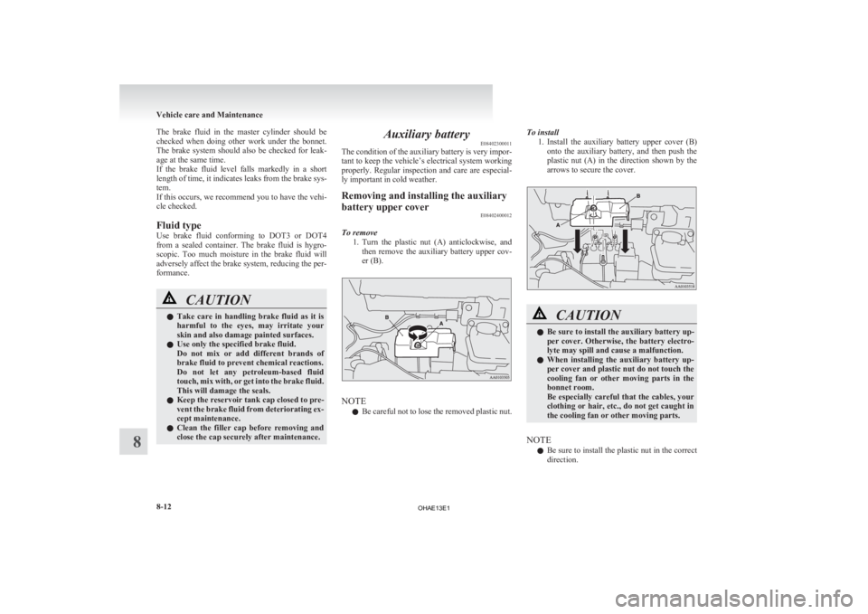
To remove 1. Turn
the plastic nut (A) anticlockwise, and
then remove the auxiliary battery upper cov-
er (B). NOTE
l Be
careful not to lose the removed plastic nut. To install
1. Install
the auxiliary battery upper cover (B)
onto the auxiliary battery, and then push the
plastic nut (A) in the direction shown by the
arrows to secure the cover. CAUTION
l
Be sure to install the auxiliary battery up-
per
cover. Otherwise, the battery electro-
lyte may spill and cause a malfunction.
l When installing the auxiliary battery up-
per cover and plastic nut do not touch the
cooling fan or other moving parts in the
bonnet room.
Be especially careful that the cables, your
clothing or hair, etc., do not get caught in
the cooling fan or other moving parts.
NOTE l Be
sure to install the plastic nut in the correct
direction. Vehicle care and Maintenance
8-12
8
OHAE13E1
Page 226 of 258
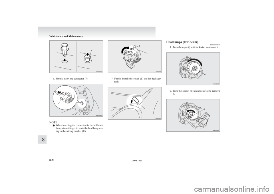
6. Firmly insert the connector (J).
NOTE
l When
inserting the connector for the left head-
lamp, do not forget to hook the headlamp wir-
ing in the wiring bracket (K). 7. Firmly
install the cover (L) on the deck gar-
nish. Headlamps (low beam)
E08405100010
1.
Turn the cap (A) anticlockwise to remove it. 2. Turn
the socket (B) anticlockwise to remove
it. Vehicle care and Maintenance
8-28
8
OHAE13E1
Page 227 of 258
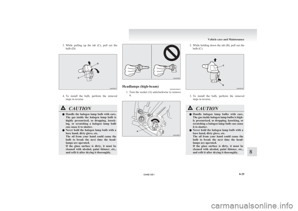
3. While pulling up the tab (C), pull out the
bulb (D). 4. To
install the bulb, perform the removal
steps in reverse. CAUTION
l
Handle
the halogen lamp bulb with care.
The gas inside the halogen lamp bulb is
highly pressurized, so dropping, knock-
ing, or scratching a halogen lamp bulb
can cause it to shatter.
l Never hold the halogen lamp bulb with a
bare hand, dirty glove, etc.
The oil from your hand could cause the
bulb to break the next time the head-
lamps are operated.
If the glass surface is dirty, it must be
cleaned with alcohol, paint thinner, etc.,
and refit it after drying it thoroughly. Headlamps (high-beam)
E08405200011
1. Turn
the socket (A) anticlockwise to remove
it. 2. While
holding down the tab (B), pull out the
bulb (C). 3. To
install the bulb, perform the removal
steps in reverse. CAUTION
l
Handle
halogen lamp bulbs with care.
The gas inside halogen lamp bulbs is high-
ly pressurized, so dropping, knocking, or
scratching a halogen lamp bulb can cause
it to shatter.
l Never hold the halogen lamp bulb with a
bare hand, dirty glove, etc.
The oil from your hand could cause the
bulb to break the next time the head-
lamps are operated.
If the glass surface is dirty, it must be
cleaned with alcohol, paint thinner, etc.,
and refit it after drying it thoroughly. Vehicle care and Maintenance
8-29 8
OHAE13E1
Page 228 of 258
Position lamps
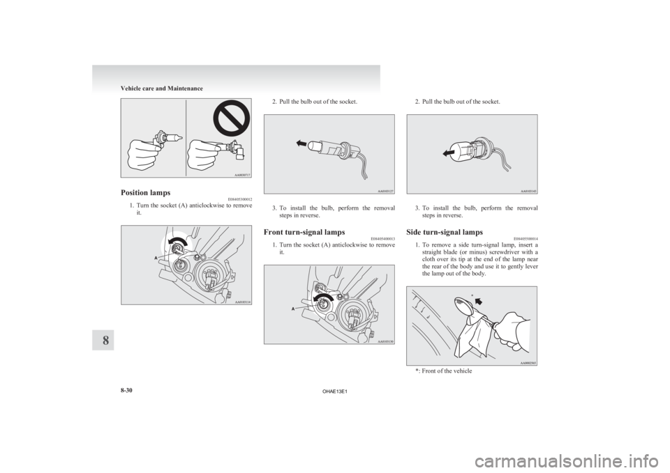
E08405300012
1. Turn the socket (A) anticlockwise to remove
it. 2. Pull the bulb out of the socket.
3. To install the bulb, perform the removal
steps in reverse.
Front turn-signal lamps E08405400013
1. Turn
the socket (A) anticlockwise to remove
it. 2. Pull the bulb out of the socket.
3. To
install the bulb, perform the removal
steps in reverse.
Side turn-signal lamps E08405500014
1. To
remove a side turn-signal lamp, insert a
straight blade (or minus) screwdriver with a
cloth over its tip at the end of the lamp near
the rear of the body and use it to gently lever
the lamp out of the body. *: Front of the vehicleVehicle care and Maintenance
8-30
8 *
OHAE13E1
Page 229 of 258
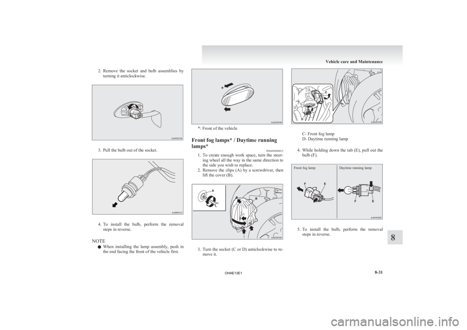
2. Remove the socket and bulb assemblies by
turning it anticlockwise. 3. Pull the bulb out of the socket.
4. To
install the bulb, perform the removal
steps in reverse.
NOTE l When installing the lamp assembly, push in
the end facing the front of the vehicle first. *: Front of the vehicle
Front fog lamps* / Daytime running
lamps* E08405600015
1. To
create enough work space, turn the steer-
ing wheel all the way in the same direction to
the side you wish to replace.
2. Remove the clips (A) by a screwdriver, then lift the cover (B). 3. Turn
the socket (C or D) anticlockwise to re-
move it. C- Front fog lamp
D- Daytime running lamp
4. While
holding down the tab (E), pull out the
bulb (F).
Front fog lamp Daytime running lamp 5. To
install the bulb, perform the removal
steps in reverse. Vehicle care and Maintenance
8-31 8
OHAE13E1
Page 230 of 258
CAUTION
l
Handle the halogen lamp bulb with care.
The gas inside a halogen lamp bulb is high-
ly pressurized, so dropping, knocking, or
scratching a halogen lamp bulb can cause
it to shatter.
l Never hold the halogen lamp bulb with a
bare hand, dirty glove, etc.
The oil from your hand could cause the
bulb to break the next time the fog lamps
are operated.
If the glass surface is dirty, it must be
cleaned with alcohol, paint thinner, etc.,
and refit it after drying it thoroughly. Rear fog lamp
E08405700016
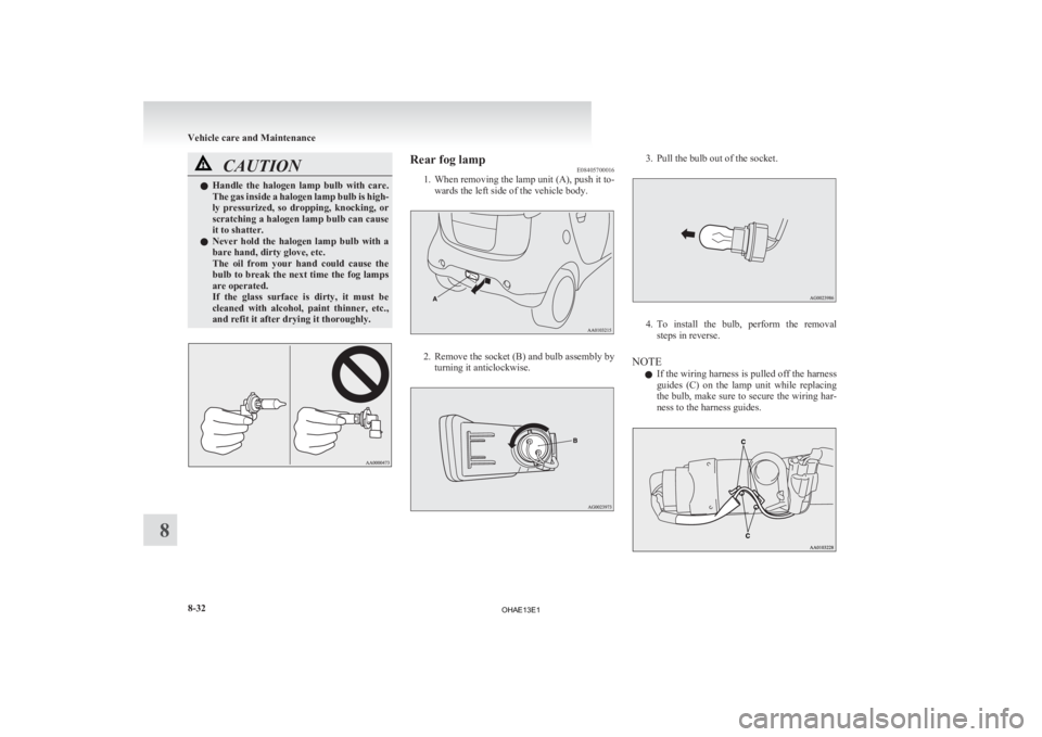
1.
When removing the lamp unit (A), push it to-wards the left side of the vehicle body. 2. Remove
the socket (B) and bulb assembly by
turning it anticlockwise. 3. Pull the bulb out of the socket.
4. To
install the bulb, perform the removal
steps in reverse.
NOTE l If the wiring harness is pulled off the harness
guides (C) on the lamp unit while replacing
the bulb, make sure to secure the wiring har-
ness to the harness guides. Vehicle care and Maintenance
8-32
8
OHAE13E1