traction control MITSUBISHI iMiEV 2013 (in English) User Guide
[x] Cancel search | Manufacturer: MITSUBISHI, Model Year: 2013, Model line: iMiEV, Model: MITSUBISHI iMiEV 2013Pages: 258, PDF Size: 13 MB
Page 58 of 258
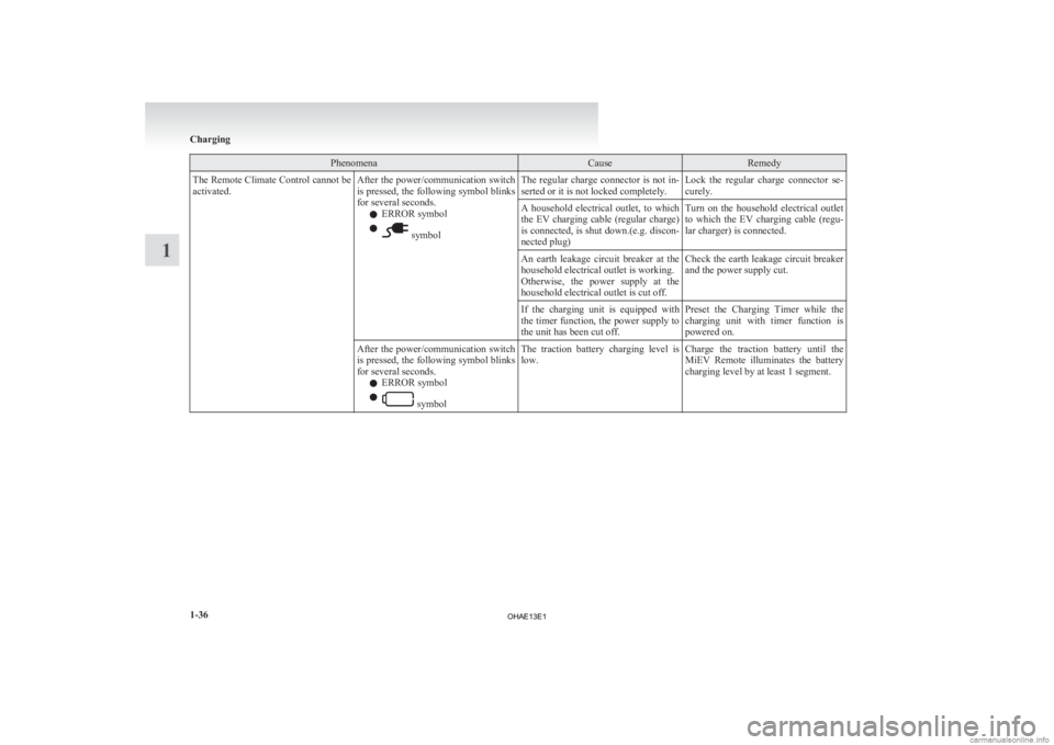
Phenomena Cause Remedy
The Remote Climate Control cannot be
activated. After the power/communication switch
is
pressed, the following symbol blinks
for several seconds.
l ERROR symbol
l symbol
The regular charge connector is not in-
serted or it is not locked completely.
Lock the regular charge connector se-
curely.
A household electrical outlet, to which
the
EV charging cable (regular charge)
is connected, is shut down.(e.g. discon-
nected plug) Turn on the household electrical outlet
to
which the EV charging cable (regu-
lar charger) is connected.
An earth leakage circuit breaker at the
household electrical outlet is working.
Otherwise,
the power supply at the
household electrical outlet is cut off. Check the earth leakage circuit breaker
and the power supply cut.
If the charging unit is equipped with
the
timer function, the power supply to
the unit has been cut off. Preset the Charging Timer while the
charging
unit with timer function is
powered on.
After the power/communication switch
is
pressed, the following symbol blinks
for several seconds.
l ERROR symbol
l symbol
The traction battery charging level is
low.
Charge the traction battery until the
MiEV
Remote illuminates the battery
charging level by at least 1 segment. Charging
1-36
1
OHAE13E1
Page 59 of 258
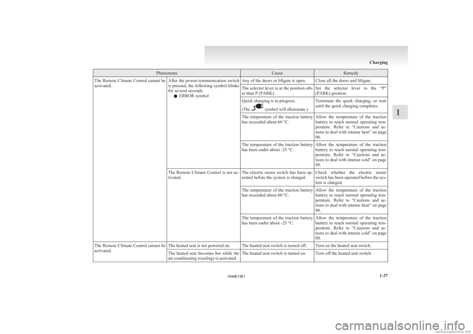
Phenomena Cause Remedy
The Remote Climate Control cannot be
activated. After the power/communication switch
is
pressed, the following symbol blinks
for several seconds.
l ERROR symbol Any of the doors or liftgate is open. Close all the doors and liftgate.
The selector lever is at the position oth-
er than P (PARK).
Set the selector lever to the “P”
(PARK) position.
Quick charging is in progress.
(The symbol will illuminate.)
Terminate the quick charging, or wait
until the quick charging completes.
The temperature of the traction battery
has exceeded about 60 °C. Allow the temperature of the traction
battery
to reach normal operating tem-
perature. Refer to “Cautions and ac-
tions to deal with intense heat” on page
06.
The temperature of the traction battery
has been under about -25 °C. Allow the temperature of the traction
battery
to reach normal operating tem-
perature. Refer to “Cautions and ac-
tions to deal with intense cold” on page
08.
The Remote Climate Control is not ac-
tivated. The electric motor switch has been op-
erated before the system is charged.Check whether the electric motor
switch
has been operated before the sys-
tem is charged.
The temperature of the traction battery
has exceeded about 60 °C. Allow the temperature of the traction
battery
to reach normal operating tem-
perature. Refer to “Cautions and ac-
tions to deal with intense heat” on page
06.
The temperature of the traction battery
has been under about -25 °C. Allow the temperature of the traction
battery
to reach normal operating tem-
perature. Refer to “Cautions and ac-
tions to deal with intense cold” on page
08.
The Remote Climate Control cannot be
activated. The heated seat is not powered on. The heated seat switch is turned off. Turn on the heated seat switch.
The heated seat becomes hot while the
air conditioning (cooling) is activated.The heated seat switch is turned on. Turn off the heated seat switch. Charging
1-37 1
OHAE13E1
Page 106 of 258
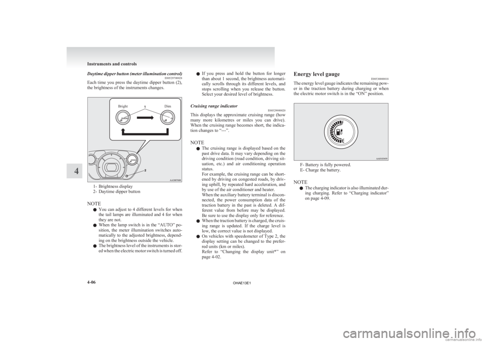
Daytime dipper button (meter illumination control)
E00529700028
Each
time you press the daytime dipper button (2),
the brightness of the instruments changes.
Bright Dim1- Brightness display
2-
Daytime dipper button
NOTE l You can adjust to 4 different levels for when
the tail lamps are illuminated and 4 for when
they are not.
l When the lamp switch is in the “AUTO” po-
sition, the meter illumination switches auto-
matically to the adjusted brightness, depend-
ing on the brightness outside the vehicle.
l The brightness level of the instruments is stor-
ed when the electric motor switch is turned off. l
If
you press and hold the button for longer
than about 1 second, the brightness automati-
cally scrolls through its different levels, and
stops scrolling when you release the button.
Select your desired level of brightness.
Cruising range indicator E00529900020
This displays the approximate cruising range (how
many
more kilometres or miles you can drive).
When the cruising range becomes short, the indica-
tion changes to “---”.
NOTE
l The cruising range is displayed based on the
past drive data. It may vary depending on the
driving condition (road condition, driving sit-
uation, etc.) and air conditioning operation
status.
For example, the cruising range can be short-
ened by driving on congested roads, by driv-
ing uphill, by repeated hard acceleration, and
by use of the air conditioner and heater.
When the auxiliary battery terminal is discon-
nected, the power consumption data of the
traction battery in the past is deleted. A dif-
ferent value from before may be displayed.
Be sure to use the display only for reference.
l When the traction battery is charged, the cruis-
ing range is updated. If the charge level is
low, the correct value is not displayed.
l On vehicles with speedometer of Type 2, the
display setting can be changed to the prefer-
red units (km or miles).
Refer to “Changing the display unit*” on
page 4-02. Energy level gauge
E00530000018
The
energy level gauge indicates the remaining pow-
er in the traction battery during charging or when
the electric motor switch is in the “ON” position. F- Battery is fully powered.
E- Charge the battery.
NOTE l The
charging indicator is also illuminated dur-
ing charging. Refer to “Charging indicator”
on page 4-09. Instruments and controls
4-06
4
OHAE13E1
Page 107 of 258
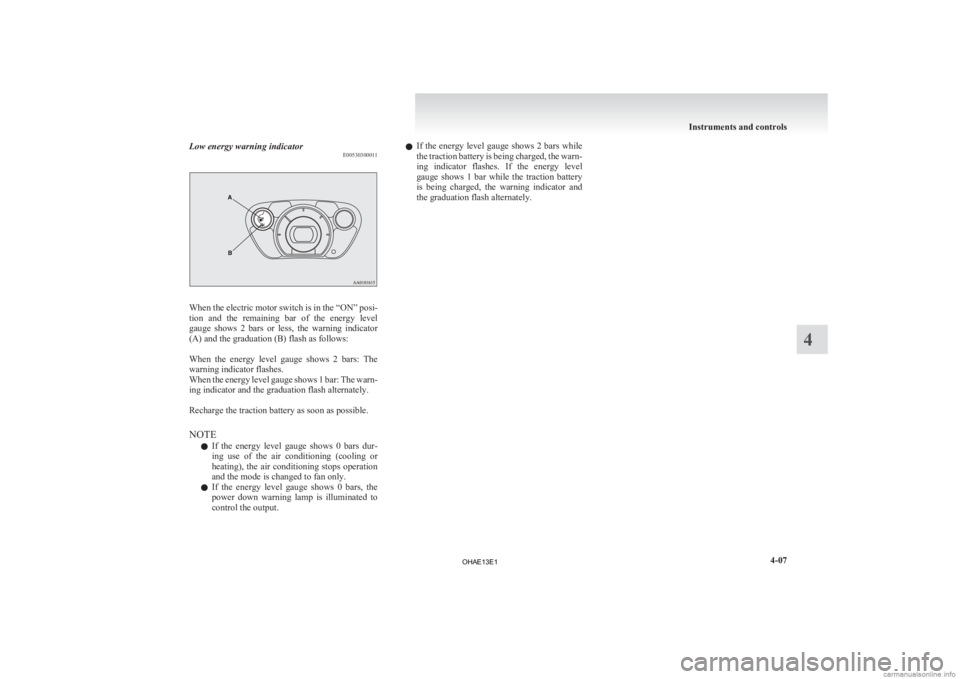
Low energy warning indicator
E00530300011When the electric motor switch is in the “ON” posi-
tion
and the remaining bar of the energy level
gauge shows 2 bars or less, the warning indicator
(A) and the graduation (B) flash as follows:
When the energy level gauge shows 2 bars: The
warning indicator flashes.
When the energy level gauge shows 1 bar: The warn-
ing indicator and the graduation flash alternately.
Recharge the traction battery as soon as possible.
NOTE
l If the energy level gauge shows 0 bars dur-
ing use of the air conditioning (cooling or
heating), the air conditioning stops operation
and the mode is changed to fan only.
l If the energy level gauge shows 0 bars, the
power down warning lamp is illuminated to
control the output. l
If
the energy level gauge shows 2 bars while
the traction battery is being charged, the warn-
ing indicator flashes. If the energy level
gauge shows 1 bar while the traction battery
is being charged, the warning indicator and
the graduation flash alternately. Instruments and controls
4-07 4
OHAE13E1
Page 111 of 258
CAUTION
l
If the lamp illuminates while
driving, immediately park your
vehicle in a safe place and we
recommend you to have it
checked. Power down warning lamp
E00530500039
If
this warning lamp illuminates, the pow-
er provided by the electric motor will be
reduced and the vehicle will only be able
to move at low speeds.
This warning lamp will illuminate;
l When the energy level in the trac-
tion battery is nearly empty.
l When temperature of the electric
motor unit or the traction battery
is too high or too low.
l When voltage of the traction bat-
tery becomes low.
If the energy level gauge shows 0 bar,
the traction battery is nearly empty and
must be charged as soon as possible. Re-
fer to “Charging” on page 1-02.
If the warning lamp illuminates when
the outside air temperature is very low,
move the vehicle to a warmer location. If the warning lamp illuminates after the
vehicle has been driven continuously up-
hill
or when the outside air temperature
is very high, stop the vehicle in a safe
place so the electric motor unit and/or
the traction battery can cool down.
When they have cooled down, the warn-
ing lamp will turn off. If the warning is
not cancelled, please contact a
MITSUBISHI MOTORS Authorized
Service Point. CAUTION
l
When
the power down warning
lamp illuminates, the vehicle
will have decreased power and
vehicle speed. The reduced
speed may be lower than other
traffic, which could increase
the chance of a collision. Be es-
pecially careful when driving.
If the vehicle cannot maintain a
safe driving speed, pull to the
side of the road in a safe place.
NOTE l Illumination
of the power down
warning lamp does not indicate a
malfunction.
l If the power down warning lamp il-
luminates while the air condition-
ing is used, the cooling or heating
may stop operating and only the
fan will operate. Combination headlamps and
dipper switch E00506002099
Headlamps
NOTE l Do
not leave the lamps on for a long time
while the ready indicator is not illuminated.
A run-down auxiliary battery could result.
l When it rains, or when the vehicle has been
washed, the inside of the lens sometimes be-
comes foggy, but this does not indicate a func-
tional problem.
When the lamp is switched on, the heat will
remove the fog. However, if water gathers in-
side the lamp, we recommend you to have it
checked.
Rotate the switch to turn on the lamps. Instruments and controls
4-11 4
OHAE13E1
Page 138 of 258
Under normal conditions, the warning lamp comes
on
when the electric motor switch is turned to the
“ON” position and goes off a few seconds later. CAUTION
l
If
the warning lamp appears while the elec-
tric motor unit is running, have the vehi-
cle inspected by a MITSUBISHI
MOTORS Authorized Service Point as
soon as possible. It may become harder to
turn the steering wheel. Active stability control (ASC)
E00616700429
The
Active Stability Control (ASC) takes overall
control of the anti-lock brake system, traction con-
trol function and stability control function to help
maintain the vehicle’s control. Please read this sec-
tion in conjunction with the page on the anti-lock
brake system, traction control function and stability
control function.
Anti-lock brake system (ABS) ® p. 5-15
Traction control function ® p. 5-18
Stability control function ® p. 5-19 CAUTION
l
Do
not over-rely on the ASC. Even the
ASC cannot prevent the natural laws of
physics from acting on the vehicle.
This system, like any other system, has
limits and cannot help you to maintain
traction and control of the vehicle in all
circumstances. Reckless driving may lead
to accidents. It is the driver’s responsibil-
ity to drive carefully. This means taking
into account the traffic, road and environ-
mental conditions.
l Be sure to use the specified type and size
of tyre on all 4 wheels. Otherwise, the
ASC may not work properly.
l Do not install any aftermarket limited-
slip differential (LSD) on your vehicle.
The ASC may stop functioning properly. NOTE
l An
operation noise may be emitted from the
bonnet room in the following situations. The
sound is associated with checking the opera-
tions of the ASC. At this time, you may feel
a shock from the brake pedal if you depress
it. These do not indicate a malfunction. • When the electric motor switch is turnedto the “ON” position.
• When the vehicle is driven for a while af- ter the electric motor is turned on.
l When the ASC is activated, you may feel a
vibration in the vehicle body or hear a whin-
ing sound from the bonnet room.
This indicates that the system is operating nor-
mally. It does not indicate a malfunction.
l When the anti-lock brake system warning
lamp is illuminated, the ASC is not active.
Traction control function E00619000087
On slippery surfaces, the traction control function
prevents
the drive wheels from spinning excessive-
ly, thus helping the vehicle to start moving from a
stopped condition. It also provides sufficient driv-
ing force and steering performance as the vehicle
turns while pressing the acceleration pedal. CAUTION
l
When
driving a vehicle on a snowy or icy
road, be sure to install snow tyres and
drive the vehicle at moderate speeds. Starting and driving
5-18
5
OHAE13E1
Page 139 of 258
Stability control function
E00619100088
The
stability control function is designed to help
the driver maintain control of the vehicle on slip-
pery roads or during rapid steering manoeuvres. It
works by controlling the electric motor unit output
and the brake on each wheel.
NOTE
l The stability control function operates at
speeds of about 15 km/h (9 mph) or higher.
“ASC OFF” switch E00619200496
The ASC is automatically activated when the elec-
tric
motor switch is turned to the “ON” position.
You can deactivate the system by pressing down
the “ASC OFF” switch for 3 seconds or longer. When the ASC is deactivated, the indication
lamp
will turn on. To reactivate the ASC, momen-
tarily press the “ASC OFF” switch; the indica-
tion lamp is turned off. CAUTION
l
For
safety reasons, the “ASC OFF”
switch should be operated when your ve-
hicle is stopped.
l Be sure to keep the ASC on while driving
in normal circumstances. NOTE
l When
moving out of mud, sand or fresh
snow, pressing the accelerator pedal may not
allow the electric motor speed to increase. In
such situations, temporarily turning off the
ASC with the “ASC OFF” switch will make
it easier to move out your vehicle.
l Using the “ASC OFF” switch turns off both
the stability control function and the traction
control function.
l If you continue to press the “ASC OFF”
switch after the ASC is turned off, the “mis-
taken operation protection function” will ac-
tivate and the ASC will turn back on.
ASC indication lamp or ASC OFF in-
dication lamp E00619300556 -
ASC indication lamp
The indication lamp will blink
when the ASC is operating. -
ASC OFF indication lamp
This indication lamp will turn on
when the ASC is turned off with the
“ASC OFF” switch. CAUTION
l
When
the indication lamp blinks, ASC
is
operating, which means that the road is
slippery or that your vehicle’s wheels are
beginning to slip. If this happens, drive
slower with less accelerator input. Starting and driving
5-19 5
OHAE13E1
Page 186 of 258
If the vehicle breaks down
E00800101355
If
the vehicle breaks down on the road, move it to
the shoulder and use the hazard warning flashers and/
or the warning triangle etc.
Refer to “Hazard warning flasher switch” on page
4-15. WARNING
l If
you are not able to safely assess the ve-
hicle due to vehicle damage, do not touch
the vehicle. Leave the vehicle and contact
a MITSUBISHI MOTORS Authorized
Service Point or another specialist and
convey that this is an electric vehicle first.
If the ready indicator goes out while
driving
Vehicle
operation and control are affected if the
ready indicator goes out while driving. Before mov-
ing the vehicle to a safe area, be aware of the fol-
lowing:
l The brake booster may become inoperative
and the pedal effort will increase. Press
down the brake pedal harder than usual.
l The power steering system may not operate,
the steering wheel feels heavy when turning it. Emergency starting
E00800502819
If
the electric motor unit cannot be started because
the auxiliary battery is weak or dead, the battery
from another vehicle can be used with jumper ca-
bles to start the electric motor unit. WARNING
l To
start the electric motor unit by using
jumper cables from another vehicle, per-
form the correct procedures according to
the instruction below. Incorrect proce-
dures could result in a fire or explosion
or damage to the vehicles. CAUTION
l
The
electric motor unit cannot be started
by pulling or pushing the vehicle.
l Always wear protective eye goggles when
working near the battery.
l Keep the battery out of the reach of chil-
dren.
l Do not attempt jump start the auxiliary
battery while the traction battery is being
charged.
Doing so could damage the charging
equipment or the vehicle.
1. Get
the vehicles close enough so the jumper cables can reach, but be sure the vehicles
aren’t touching each other. CAUTION
l
Check
the other vehicle. It must have a 12-
volt battery.
If the other system isn’t 12-volt, shorting
can damage both vehicles.
2. Turn
off all lamps, heater and other electrical loads.
3. Set the parking brake firmly on your vehicle and move the selector lever into the “P” posi-
tion.
4. Set the parking brake firmly on another vehi- cle. Put an A/T in “P” (PARK) or a M/T in
“N” (Neutral).
5. Turn the ignition switch or the electric motor switch to the “LOCK” position. WARNING
l Perform
step 5 on both vehicles before-
hand.
Make sure that the cables or your clothes
cannot be caught by the fan or drive belt.
Personal injury could result.
6. Remove
the battery cover, and then make sure auxiliary battery electrolyte is at the prop-
er level.
Refer to “Auxiliary battery” on page 8-12. For emergencies
7-02
7
OHAE13E1
Page 195 of 258
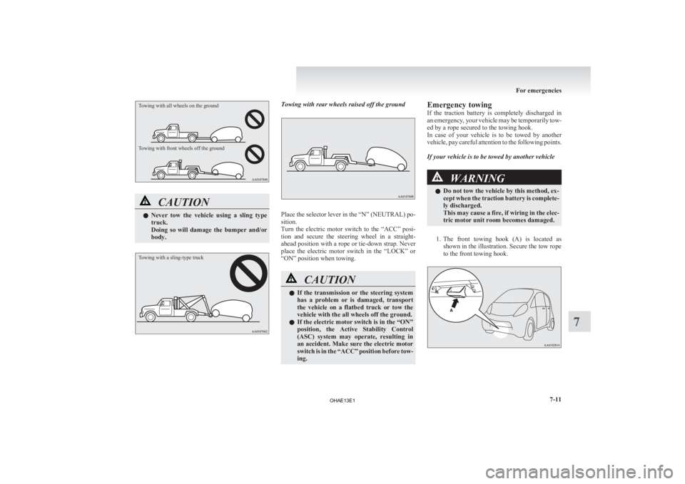
Towing with all wheels on the ground
Towing with front wheels off the groundCAUTION
l
Never
tow the vehicle using a sling type
truck.
Doing so will damage the bumper and/or
body.
Towing with a sling-type truck Towing with rear wheels raised off the ground
Place the selector lever in the “N” (NEUTRAL) po-
sition.
Turn
the electric motor switch to the “ACC” posi-
tion and secure the steering wheel in a straight-
ahead position with a rope or tie-down strap. Never
place the electric motor switch in the “LOCK” or
“ON” position when towing. CAUTION
l
If
the transmission or the steering system
has a problem or is damaged, transport
the vehicle on a flatbed truck or tow the
vehicle with the all wheels off the ground.
l If the electric motor switch is in the “ON”
position, the Active Stability Control
(ASC) system may operate, resulting in
an accident. Make sure the electric motor
switch is in the “ACC” position before tow-
ing. Emergency towing
If
the traction battery is completely discharged in
an emergency, your vehicle may be temporarily tow-
ed by a rope secured to the towing hook.
In case of your vehicle is to be towed by another
vehicle, pay careful attention to the following points.
If your vehicle is to be towed by another vehicle WARNING
l Do not tow the vehicle by this method, ex-
cept
when the traction battery is complete-
ly discharged.
This may cause a fire, if wiring in the elec-
tric motor unit room becomes damaged.
1. The
front towing hook (A) is located as shown in the illustration. Secure the tow rope
to the front towing hook. For emergencies
7-11 7
OHAE13E1
Page 245 of 258
A
Accessory (Installation) 04
Accessory socket 6-36
Active stability control (ASC)
5-18
Additional equipment 8-20
Air conditioning Important operation tips for the air condition-
ing 6-09
Air purifier 6-09
Airbag 3-20
Antenna 6-30
Anti-lock brake system (ABS) 5-15 Warning lamp 5-16
Assist grips 6-41
Audio Error codes 6-26
Handling of compact discs 6-29
LW/MW/FM electronic tuning radio with CD
player 6-10
Auxiliary battery 8-12 Specification 9-05
Auxiliary battery charge warning lamp 4-10
BBasic knowledge for charging 1-04
Battery
Auxiliary battery
8-12
Auxiliary battery charge warning lamp 4-10
Discharged battery (Emergency starting) 7-02
Disposal information for used batteries 05
Traction battery 02
Bonnet 8-07
Brake assist system 5-15
Brake Anti-lock brake 5-15
Braking 5-14 Fluid 8-11,9-08
Parking brake 5-03
Warning lamp 4-09
Bulb capacity
8-23C Capacities 9-08
Card holder 6-36,6-39
Cargo loads 5-20
Central door locks 2-06
Charging indicator
4-09
Charging Quick charging 1-12
Regular charging 1-08
Child restraint 3-11
Child-protection rear doors 2-07
Cleaning Exterior of your vehicle 8-03
Interior of your vehicle 8-02
Plastic, vinyl leather, etc. 8-02
Clock 6-31
Cold Cautions and actions to deal with intense
cold 08
Combination headlamps and dipper switch 4-11
Coolant 8-09,9-08
Cruising range 03,9-07
Cruising range indicator 4-03,4-06
Cup holder 6-40
D Daytime running lamps 4-13
Bulb capacity
8-24
Replacement 8-31
Demister (rear window) 4-18
Digital clock 6-31
Dimensions 9-03 Dipper (High/Low beam change) 4-13
Door ajar warning lamp 4-10
Doors
Central door locks 2-06
Child-protection
2-07
Lock and unlock 2-05
Driving the vehicle 5-11
Driving, alcohol and drugs 5-02
E Economical driving 5-02
Electric motor switch
5-07
Electric motor unit Warning lamp 4-10
Electric motor Number 9-02
Specifications 9-05
Electric power steering system (EPS) 5-17
Electric window control 2-09 Driver’s switches 2-09
Lock switch 2-09
Passenger’s switches 2-09
Timer function 2-10
Electronic immobilizer (Anti-theft starting sys-
tem) 2-02
Emergency starting 7-02
Energy level gauge 4-06
Energy usage indicator 4-03
Error codes 6-26
EV charging cable 1-05
Exterior and interior lamp operation 8-19
F Fluid capacities and lubricants 9-08
Fluid
Brake fluid 8-11,9-08
Coolant 8-09 Alphabetical index
1
OHAE13E1