bonnet MITSUBISHI iMiEV 2013 Owner's Manual (in English)
[x] Cancel search | Manufacturer: MITSUBISHI, Model Year: 2013, Model line: iMiEV, Model: MITSUBISHI iMiEV 2013Pages: 258, PDF Size: 13 MB
Page 6 of 258
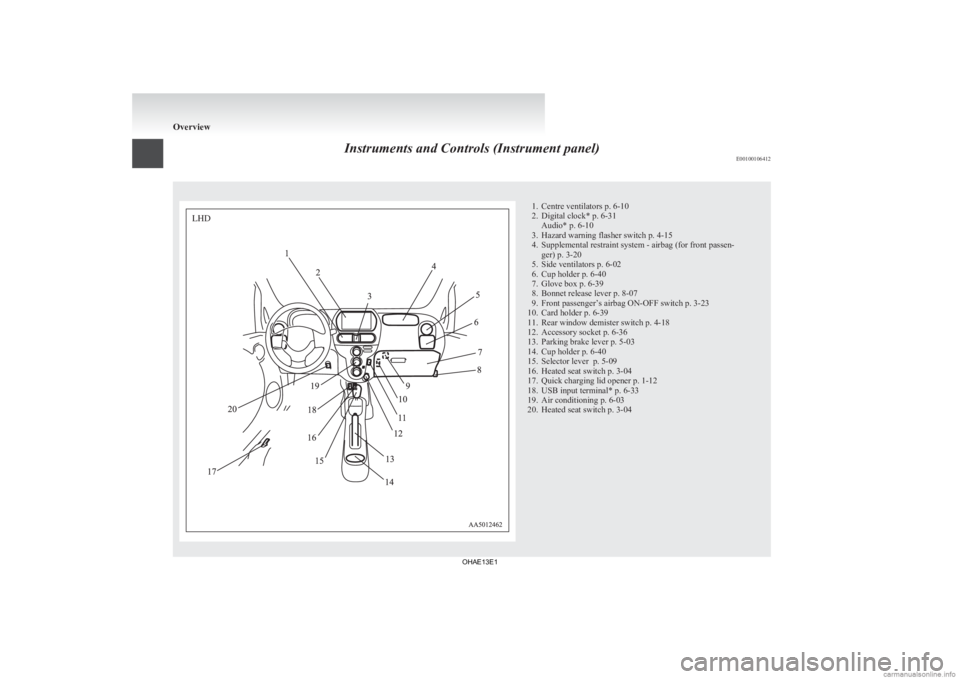
Instruments and Controls (Instrument panel)
E001001064121. Centre ventilators p. 6-10
2.
Digital clock* p. 6-31Audio* p. 6-10
3. Hazard warning flasher switch p. 4-15
4. Supplemental restraint system - airbag (for front passen- ger) p. 3-20
5. Side ventilators p. 6-02
6. Cup holder p. 6-40
7. Glove box p. 6-39
8. Bonnet release lever p. 8-07
9. Front passenger’s airbag ON-OFF switch p. 3-23
10. Card holder p. 6-39
11. Rear window demister switch p. 4-18
12. Accessory socket p. 6-36
13. Parking brake lever p. 5-03
14. Cup holder p. 6-40
15. Selector lever p. 5-09
16. Heated seat switch p. 3-04
17. Quick charging lid opener p. 1-12
18. USB input terminal* p. 6-33
19. Air conditioning p. 6-03
20. Heated seat switch p. 3-04 OverviewLHD
OHAE13E1
Page 7 of 258
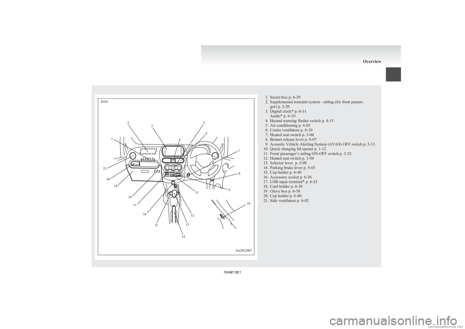
1. Secret box p. 6-39
2.
Supplemental restraint system - airbag (for front passen-ger) p. 3-20
3. Digital clock* p. 6-31 Audio* p. 6-10
4. Hazard warning flasher switch p. 4-15
5. Air conditioning p. 6-03
6. Centre ventilators p. 6-10
7. Heated seat switch p. 3-04
8. Bonnet release lever p. 8-07
9. Acoustic Vehicle Alerting System (AVAS) OFF switch p. 5-13
10. Quick charging lid opener p. 1-12
11. Front passenger’s airbag ON-OFF switch p. 3-23
12. Heated seat switch p. 3-04
13. Selector lever p. 5-09
14. Parking brake lever p. 5-03
15. Cup holder p. 6-40
16. Accessory socket p. 6-36
17. USB input terminal* p. 6-33
18. Card holder p. 6-39
19. Glove box p. 6-39
20. Cup holder p. 6-40
21. Side ventilators p. 6-02 OverviewRHD
OHAE13E1
Page 10 of 258
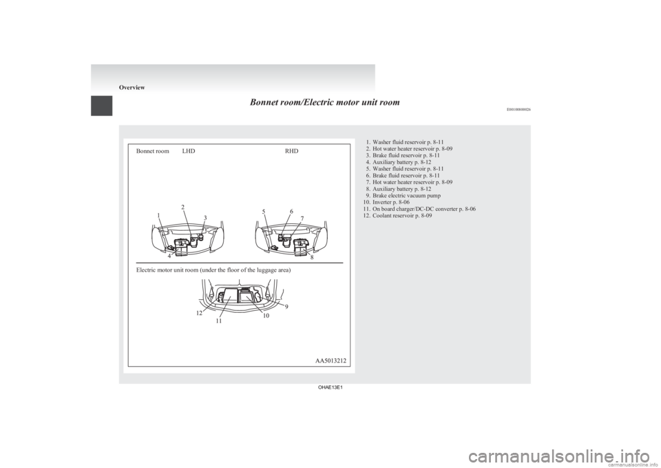
Bonnet room/Electric motor unit room
E00100800026Bonnet room
Electric motor unit room (under the floor of the luggage area)LHD
RHD 1. Washer fluid reservoir p. 8-11
2.
Hot water heater reservoir p. 8-09
3. Brake fluid reservoir p. 8-11
4. Auxiliary battery p. 8-12
5. Washer fluid reservoir p. 8-11
6. Brake fluid reservoir p. 8-11
7. Hot water heater reservoir p. 8-09
8. Auxiliary battery p. 8-12
9. Brake electric vacuum pump
10. Inverter p. 8-06
11. On board charger/DC-DC converter p. 8-06
12. Coolant reservoir p. 8-09 Overview
OHAE13E1
Page 11 of 258
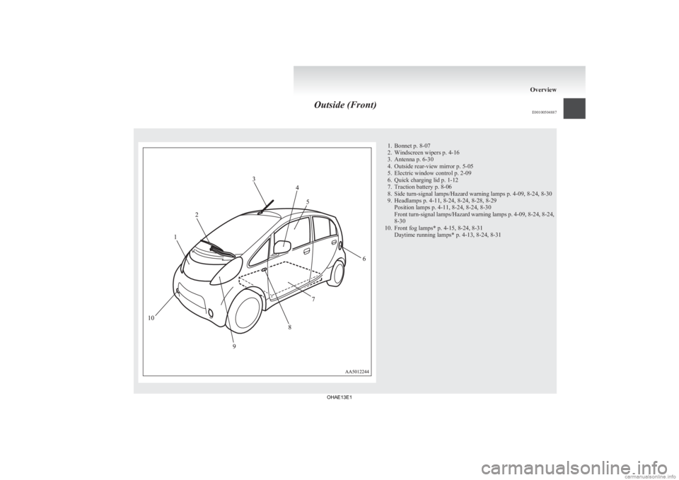
Outside (Front)
E00100504887 1. Bonnet p. 8-07
2.
Windscreen wipers p. 4-16
3. Antenna p. 6-30
4. Outside rear-view mirror p. 5-05
5. Electric window control p. 2-09
6. Quick charging lid p. 1-12
7. Traction battery p. 8-06
8. Side turn-signal lamps/Hazard warning lamps p. 4-09, 8-24, 8-30
9. Headlamps p. 4-11, 8-24, 8-24, 8-28, 8-29 Position lamps p. 4-11, 8-24, 8-24, 8-30
Front turn-signal lamps/Hazard warning lamps p. 4-09, 8-24, 8-24,
8-30
10. Front fog lamps* p. 4-15, 8-24, 8-31 Daytime running lamps* p. 4-13, 8-24, 8-31 Overview
OHAE13E1
Page 30 of 258
Regular charging (charging
method with rated AC 220-240 V outlet) E08300900054WARNING
l For safety, do not allow children or peo-
ple who are not familiar with charging to
charge for themselves. Also, do not use
the charge connector within reach of chil-
dren.
l Persons who use electro-medical appara-
tus such as implantable cardiac pacemak-
er or implantable cardioverter defibrilla-
tor must check effect from charging with
the manufacturer of electro-medical appa-
ratus.
l If you use any medical electric devices,
take into account the following precau-
tions.
• Do not stay inside the vehicle.
• Do not go inside the vehicle, for exam-ple to remove or place an item in the
passenger compartment.
• Do not open the rear hatch, for exam- ple to remove or place an item in the
cargo area.
Charging may affect the operation of elec-
tric medical devices and result in serious
personal injury or death.
l Do not charge with the EV charging ca-
ble banded or rolled.
Doing so the cable may be heated and this
might result in fire. WARNING
l Before
charging, make sure that there is
no foreign matter such as dust at the reg-
ular charge port and the regular charge
connector.
At this time, do not touch the regular
charge port.
l When the regular charge connector is con-
nected to the charge port, prevent foreign
matter such as water or dust from enter-
ing in the port.
Connection with foreign matter such as
water or dust may cause fire or an elec-
tric shock. Do not perform charging if
there might be strong exposure to water
at the connection.
l Never pull the cable to remove the plug.
And never submerge the EV charging con-
nector, control box or plug in water.
l Please observe the following in order to
prevent accidents during charging such
as electrocution.
• Always use a charging cable that suit-able for this vehicle.
• Do not charge another vehicle using the attached EV charging cable.
Doing so the cable may be heated and
this might result in fire.
• Make sure to use an outlet that is pro- tected from water entering.
• Do not perform charging with the body cover.
• Do not remove and insert the plug and connector with wet hands.
• Do not charge the battery if there is a risk of lightning. WARNING
l While it is normal for the connector and
charging cable to become warm during
charging, discontinue use immediately if
the connector or charging cable becomes
hot to the touch.
l While it is normal for the control box to
become warm during charging, discontin-
ue use immediately if the control box be-
comes hot to the touch.
l If abnormal smells are detected or the ve-
hicle produces smoke, quickly stop charg-
ing.
l Do not perform charging at a poorly ven-
tilated place with surroundings covered.
Keep sparks, cigarettes, and flames away
from the auxiliary battery.
Flammable gas generated from the auxili-
ary battery in charging may be filled in a
building, resulting in explosion.
If charging is inevitably required, venti-
late the area well.
l Grasp the regular charge connector when
connecting or disconnecting the EV charg-
ing cable.
Grasping the cable could cause an elec-
tric shock, short circuit, and/or fire.
l During charging, the cooling fans inside
the bonnet room may automatically be op-
erated even if the electric motor switch is
in the “LOCK” position.
Keep your hands away from the cooling
fan during charging. Charging
1-08
1
OHAE13E1
Page 35 of 258
WARNING
l When the quick charge connector is con-
nected to the quick charge port, prevent
foreign matter such as water or dust
from entering in the port.
Connection with foreign matter such as
water or dust may cause fire or an elec-
tric shock. Do not perform charging if
there might be strong exposure to water
at the connection.
l During charging, the cooling fans inside
the bonnet room may automatically be op-
erated even if the electric motor switch is
in the “LOCK” position.
Keep your hands away from the cooling
fan during charging.
NOTE l If
the charge connector is not easily connec-
ted to the charge port due to foreign material
entering, never force the connection. Doing
so could damage the charging equipment or
the vehicle. Contact a MITSUBISHI
MOTORS Authorized Service Point.
l The quick charger might be installed in the
public parking space, some chargers are not
suitable for this vehicle. Check the manual of
each quick charger when charging.
l The charge connector and the EV charging ca-
ble stick out of the vehicle body while charg-
ing, so be careful that your body does not get
stuck with them or they do not touch the next
vehicle. l
The
vehicle equipped with a quick charge
port is compatible with most CHAdeMO (Jap-
anese industry standard) connectors on charg-
ing stations.
l Make sure to lock the doors to prevent theft,
etc. during charging.
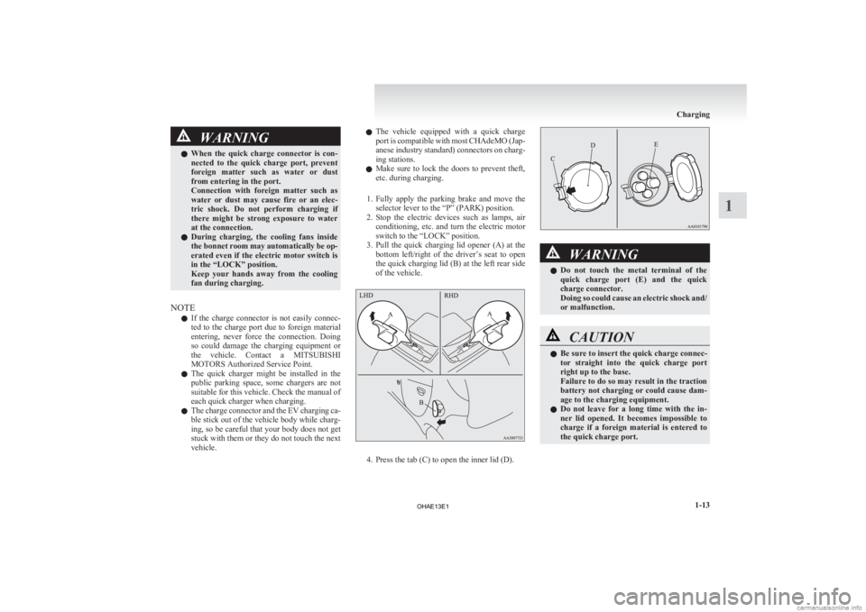
1. Fully apply the parking brake and move the selector lever to the “P” (PARK) position.
2. Stop the electric devices such as lamps, air conditioning, etc. and turn the electric motor
switch to the “LOCK” position.
3. Pull the quick charging lid opener (A) at the bottom left/right of the driver’s seat to open
the quick charging lid (B) at the left rear side
of the vehicle. 4. Press the tab (C) to open the inner lid (D). WARNING
l Do
not touch the metal terminal of the
quick charge port (E) and the quick
charge connector.
Doing so could cause an electric shock and/
or malfunction. CAUTION
l
Be sure to insert the quick charge connec-
tor
straight into the quick charge port
right up to the base.
Failure to do so may result in the traction
battery not charging or could cause dam-
age to the charging equipment.
l Do not leave for a long time with the in-
ner lid opened. It becomes impossible to
charge if a foreign material is entered to
the quick charge port. Charging
1-13 1
OHAE13E1
Page 50 of 258
NOTE
l If
the manual charging switch (H) is pressed,
the symbol of MiEV Remote will blink.
The Remote Climate Control is also stopped.
3. Cancelling
Charging Timer is complete,
and the MiEV Remote will sound two dif-
ferent melodies.
4. Turn off the MiEV Remote. Refer to “To turn the MiEV Remote ON/OFF” on
page 1-24.
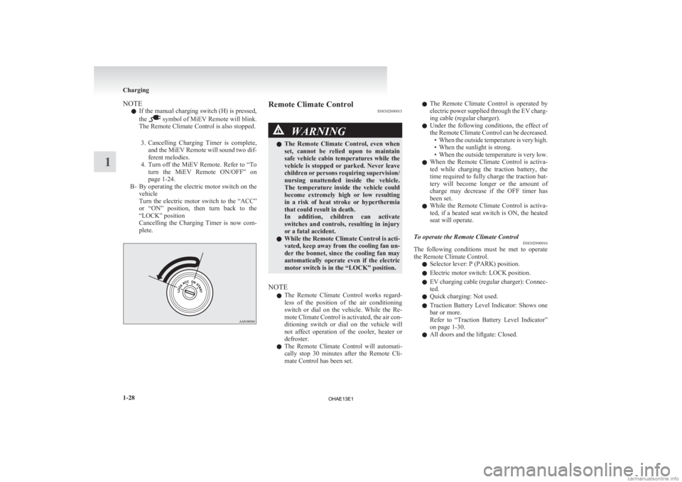
B- By operating the electric motor switch on the vehicle
Turn the electric motor switch to the “ACC”
or “ON” position, then turn back to the
“LOCK” position
Cancelling the Charging Timer is now com-
plete. Remote Climate Control
E08302800015 WARNING
l The
Remote Climate Control, even when
set, cannot be relied upon to maintain
safe vehicle cabin temperatures while the
vehicle is stopped or parked. Never leave
children or persons requiring supervision/
nursing unattended inside the vehicle.
The temperature inside the vehicle could
become extremely high or low resulting
in a risk of heat stroke or hyperthermia
that could result in death.
In addition, children can activate
switches and controls, resulting in injury
or a fatal accident.
l While the Remote Climate Control is acti-
vated, keep away from the cooling fan un-
der the bonnet, since the cooling fan may
automatically operate even if the electric
motor switch is in the “LOCK” position.
NOTE l The
Remote Climate Control works regard-
less of the position of the air conditioning
switch or dial on the vehicle. While the Re-
mote Climate Control is activated, the air con-
ditioning switch or dial on the vehicle will
not affect operation of the cooler, heater or
defroster.
l The Remote Climate Control will automati-
cally stop 30 minutes after the Remote Cli-
mate Control has been set. l
The
Remote Climate Control is operated by
electric power supplied through the EV charg-
ing cable (regular charger).
l Under the following conditions, the effect of
the Remote Climate Control can be decreased.
• When the outside temperature is very high.
• When the sunlight is strong.
• When the outside temperature is very low.
l When the Remote Climate Control is activa-
ted while charging the traction battery, the
time required to fully charge the traction bat-
tery will become longer or the amount of
charge may decrease if the OFF timer has
been set.
l While the Remote Climate Control is activa-
ted, if a heated seat switch is ON, the heated
seat will operate.
To operate the Remote Climate Control E08302900016
The following conditions must be met to operate
the Remote Climate Control.
l Selector lever: P (PARK) position.
l Electric motor switch: LOCK position.
l EV
charging cable (regular charger): Connec-
ted.
l Quick charging: Not used.
l Traction Battery Level Indicator: Shows one
bar or more.
Refer to “Traction Battery Level Indicator”
on page 1-30.
l All doors and the liftgate: Closed. Charging
1-28
1
OHAE13E1
Page 135 of 258
Brake assist system
E00627000174
The brake assist system is a device assisting drivers
who
cannot depress the brake pedal firmly when it
is necessary to do so (such as in emergency stop sit-
uations) and provides greater braking force.
If the brake pedal is depressed suddenly, the brakes
will be applied with more force than usual. CAUTION
l
The
brake assist system is not a device de-
signed to exercise braking force greater
than its capacity. Make sure to always
keep a sufficient distance between vehi-
cles in front of you without relying too
much on the brake assist system.
NOTE l Once
the brake assist system is operational,
it maintains great braking force even if the
brake pedal is lightly released.
To stop its operation, completely remove
your foot from the brake pedal.
l The brake assist system may become opera-
tional when the brake pedal is fully de-
pressed even if it has not been depressed sud-
denly. l
When
the brake assist system is in use, you
may feel as if the depressed brake pedal is
soft, the pedal moves in small motions in con-
junction with the sound of the ABS opera-
tion, or the vehicle body and the steering
wheel vibrate. This occurs when the brake as-
sist system is operating normally and does
not indicate faulty operation. Continue to
firmly depress the brake pedal.
l You may hear an operation noise when the
brake pedal is depressed suddenly while sta-
tionary. This does not indicate a malfunction
and the brake assist system is operating nor-
mally. Anti-lock brake system (ABS)
E00607101394
The
anti-lock brake system (ABS) helps prevent
the wheels from locking during braking. This helps
maintain vehicle drivability and steering wheel han-
dling.
Driving hints
l Always keep a safe distance from the vehicle
in front of you. Even if your vehicle is equip-
ped with ABS, leave a greater braking dis-
tance when:
• Driving on gravel or snow-covered roads.
• Driving with tyre chains installed.
• Driving on uneven road surfaces.
l Operation of ABS is not restricted to situa-
tions where brakes are applied suddenly.
This system may also prevent the wheels
from locking when you drive over manholes,
steel roadwork plates, road markings, or any
uneven road surface.
l When the ABS is activated, you may feel the
brake pedal pulsation and the vibrations of
the vehicle body and steering wheel. It may
also feel as if the pedal resists being pressed.
In this situation, simply hold the brake ped-
al down firmly. Do not pump the brake,
which will result in reduced braking per-
formance.
l An operation noise may be emitted from the
bonnet room in the following situations. The
sound is associated with checking the opera-
tions of the anti-lock brake system.
At this time, you may feel a shock from the
brake pedal if you depress it. These do not in-
dicate a malfunction.
• When the electric motor switch is turnedto the “ON” position. Starting and driving
5-15 5
OHAE13E1
Page 138 of 258
Under normal conditions, the warning lamp comes
on
when the electric motor switch is turned to the
“ON” position and goes off a few seconds later. CAUTION
l
If
the warning lamp appears while the elec-
tric motor unit is running, have the vehi-
cle inspected by a MITSUBISHI
MOTORS Authorized Service Point as
soon as possible. It may become harder to
turn the steering wheel. Active stability control (ASC)
E00616700429
The
Active Stability Control (ASC) takes overall
control of the anti-lock brake system, traction con-
trol function and stability control function to help
maintain the vehicle’s control. Please read this sec-
tion in conjunction with the page on the anti-lock
brake system, traction control function and stability
control function.
Anti-lock brake system (ABS) ® p. 5-15
Traction control function ® p. 5-18
Stability control function ® p. 5-19 CAUTION
l
Do
not over-rely on the ASC. Even the
ASC cannot prevent the natural laws of
physics from acting on the vehicle.
This system, like any other system, has
limits and cannot help you to maintain
traction and control of the vehicle in all
circumstances. Reckless driving may lead
to accidents. It is the driver’s responsibil-
ity to drive carefully. This means taking
into account the traffic, road and environ-
mental conditions.
l Be sure to use the specified type and size
of tyre on all 4 wheels. Otherwise, the
ASC may not work properly.
l Do not install any aftermarket limited-
slip differential (LSD) on your vehicle.
The ASC may stop functioning properly. NOTE
l An
operation noise may be emitted from the
bonnet room in the following situations. The
sound is associated with checking the opera-
tions of the ASC. At this time, you may feel
a shock from the brake pedal if you depress
it. These do not indicate a malfunction. • When the electric motor switch is turnedto the “ON” position.
• When the vehicle is driven for a while af- ter the electric motor is turned on.
l When the ASC is activated, you may feel a
vibration in the vehicle body or hear a whin-
ing sound from the bonnet room.
This indicates that the system is operating nor-
mally. It does not indicate a malfunction.
l When the anti-lock brake system warning
lamp is illuminated, the ASC is not active.
Traction control function E00619000087
On slippery surfaces, the traction control function
prevents
the drive wheels from spinning excessive-
ly, thus helping the vehicle to start moving from a
stopped condition. It also provides sufficient driv-
ing force and steering performance as the vehicle
turns while pressing the acceleration pedal. CAUTION
l
When
driving a vehicle on a snowy or icy
road, be sure to install snow tyres and
drive the vehicle at moderate speeds. Starting and driving
5-18
5
OHAE13E1
Page 187 of 258
WARNING
l If electrolyte fluid is not visible, or ap-
pears to be frozen, Do Not Attempt Jump
Starting!
A battery might rupture or explode if the
temperature is below the freezing point
or if it is not filled to the proper level.
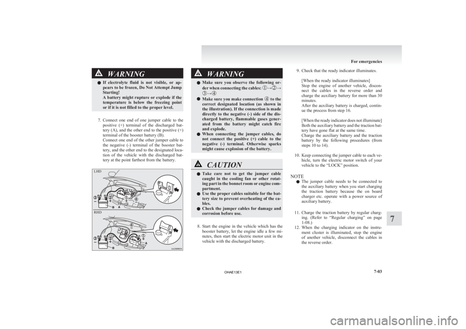
7. Connect
one end of one jumper cable to the positive (+) terminal of the discharged bat-
tery (A), and the other end to the positive (+)
terminal of the booster battery (B).
Connect one end of the other jumper cable to
the negative (-) terminal of the booster bat-
tery, and the other end to the designated loca-
tion of the vehicle with the discharged bat-
tery at the point farthest from the battery. WARNING
l Make
sure you observe the following or-
der when connecting the cables: → →
→
l
Make sure you make connection to the
correct
designated location (as shown in
the illustration). If the connection is made
directly to the negative (-) side of the dis-
charged battery, flammable gases gener-
ated from the battery might catch fire
and explode.
l When connecting the jumper cables, do
not connect the positive (+) cable to the
negative (-) terminal. Otherwise sparks
might cause explosion of the battery. CAUTION
l
Take
care not to get the jumper cable
caught in the cooling fan or other rotat-
ing part in the bonnet room or engine com-
partment.
l Use the proper cables suitable for the bat-
tery size to prevent overheating of the ca-
bles.
l Check the jumper cables for damage and
corrosion before use.
8. Start
the engine in the vehicle which has the booster battery, let the engine idle a few mi-
nutes, then start the electric motor unit in the
vehicle with the discharged battery.
9. Check that the ready indicator illuminates.
[When the ready indicator illuminates]
Stop
the engine of another vehicle, discon-
nect the cables in the reverse order and
charge the auxiliary battery for more than 30
minutes.
After the auxiliary battery is charged, contin-
ue the process from step 16.
[When the ready indicator does not illuminate]
Both the auxiliary battery and the traction bat-
tery have gone flat at the same time.
Charge the auxiliary battery and the traction
battery by the following procedures (from
steps 10 to 14).
10. Keep connecting the jumper cable to each ve- hicle, turn the electric motor switch of your
vehicle to the “LOCK” position.
NOTE l The jumper cable needs to be connected to
the auxiliary battery when you start charging
the traction battery because the on board
charger etc. operate with a power source of
auxiliary battery.
11. Charge the traction battery by regular charg- ing. (Refer to “Regular charging” on page
1-08.)
12. When the charging indicator on the instru- ment cluster is illuminated, stop the engine
of another vehicle, disconnect the cables in
the reverse order. For emergencies
7-03 7 LHD
RHD
OHAE13E1