air condition MITSUBISHI iMiEV 2015 (in English) User Guide
[x] Cancel search | Manufacturer: MITSUBISHI, Model Year: 2015, Model line: iMiEV, Model: MITSUBISHI iMiEV 2015Pages: 262, PDF Size: 26.84 MB
Page 58 of 262

MiEV Remote System
General information/Charging 3-43
3
N01204201035
N01204301036
The following conditions must be met to operate the Remote Climate Control. Selector lever:
P (PARK) position.
Electric motor switch: LOCK position. EV charging cable (re
gular charger): Con-
nected. Quick charging: Not used. Main Drive Lithium-ion Battery Level Indicator: Shows one bar or more. Refer to “Main Drive Lithium-ion Battery LevelIndicator” on page 3-45. All doors and the liftgate: Closed. 1. Start charging. Refer to “Regular charging (charging method with rated AC 120 V outlet)” on page 3-15.
Remote Climate Control
WA R N I N G The Remote Climate Control, even when set, cannot be relied upon to maintain safevehicle cabin temperatures while the vehi- cle is stopped or park
ed. Never leave chil-
dren or persons requiringsupervision/nursing unattended inside the vehicle. Temperature inside the vehicle could become extremely high or lowresulting in a risk of
heat stroke or hyper-
thermia that could result in death. In addition, children
can activate switches
and controls, resulting in an injury or fatal accident. While the Remote Climate Control is acti- vated, keep away from
the cooling fan
under the front hood,
since the cooling fan
may automatically operate even if the electric motor switch is in the “LOCK” position.NOTE
The Remote Climate Control works regard- less the position of the air conditioningswitch or dial on the vehicle. While the Remote Climate Control is activated, the air conditioning switch or di
al on the vehicle
will not affect operation
of the cooler, heater
or defroster.
The Remote Climate Control will automati- cally stop 30 minutes after the Remote Cli-mate Control has been set. The Remote Climate Control is operated by electric power s
upplied through the EV
charging cable (regular charger). Under the following c
onditions, the effect of
the Remote Climate Control can be decreased. • When the outside temperature is very high. • When the sunlight is strong.• When the outside temperature is very low. When Remote Climate Control is activated while charging the Main Drive Lithium-ion Battery, the time required to fully charge theMain Drive Lithium-ion Battery will become longer or the amount of charge may decrease if the OFF timer has been set. If the Main Drive Lithium-ion Battery Warming System is operated while theRemote Climate Control is activated, the Remote Climate Control will stop. When the Main Drive Lithium-ion Battery WarmingSystem stops, the Remote Climate Control will resume. Refer to “Main Drive Lithium- ion Battery Warming System” on page 3-20. While the Remote Climate Control is acti- vated, if a heated seat switch is ON, theheated seat will operate.NOTE
To operate the Remote Climate Control
WA R N I N G Improper charging can result in a fire, property damage, and serious injury ordeath. Carefully read and fo
llow instructions in
“Precaution during Charging the MainDrive Lithium-ion Battery” on page 3-14 and “Regular chargi
ng (charging method
with rated AC 120 V ou
tlet)” on page 3-15.
BK0209800US.book 43 ページ 2014年1月14日 火曜日 午前9時26分
Page 93 of 262

Supplemental Restraint System (SRS) - airbag 4-24 Seat and restraint systems
4
When airbags deploy, so
me smoke is released
accompanied by a loud noise. The smoke isnot harmful, but do not intentionally inhale the smoke as it may ca
use temporary irrita-
tion to people with respiratory problems. After deployment, the airbags will quickly deflate, so quickly th
at some people may not
even realize the airbags inflated. Airbag inflation does
not prevent the driver
from seeing or being able
to steer the vehicle,
and does not prevent people from leaving the vehicle.
N00418600227
This vehicle is equipped with an event data recorder (EDR). The main purpose of an EDR is to record, incertain crash or near crash-like situations, such as an airbag deployment or hitting a road obstacle, data that
will assist in under-
standing how a vehicle’s systems performed. The EDR is designed to
record data related to
vehicle dynamics and sa
fety systems for a
short period of time,
typically 30 seconds or
less. The EDR in this vehicle is designed to record such data as: How various systems
in your vehicle were
operating; Whether or not the driver safety belt was buckled/fastened; How far (if at all) the driver was depress- ing the accelerator and/or brake pedal; and, How fast the vehicle was traveling.
These data can help provide a better under- standing of the circumstances in which crashes and injuries occur. To read data recorded
by an EDR, special
equipment is required, a
nd access to the vehi-
cle or the EDR is needed. In addition to the vehicle manufacturer, ot
her parties, such as
law enforcement, that have the special equip- ment, can read the information if they have access to the vehicle or the EDR.
N00417900210
The driver’s seat position sensor is attachedto the seat rail and provides the airbag control unit with information on the seat’s fore-aft position. The airbag control unit controlsdeployment of the driver’s front airbag in accordance with the information it receives from this sensor.If there is a problem involving the driver’s seat position sensor, the SRS warning light in the instrument panel will come on. Refer to“SRS warning light” on page 4-26.
CAUTION Airbags inflate very quickly and with great force. In certain situ
ations, contact with an
inflating airbag may cause small cuts, abra- sions, and bruises.
Event Data Recording
NOTE
EDR data are recorded by your vehicle only if a non-trivial crash situation occurs; no dataare recorded by the EDR under normal driv- ing conditions and no
personal data (e.g.,
name, gender, age, and crash location) arerecorded. However, other parties, such as law enforcement, could combine the EDR data with the type of personally identifyingdata routinely acquire
d during a crash inves-
tigation.
Driver’s seat position sensor
WA R N I N G If the SRS warning
light comes on, have
the vehicle inspected by a certified i-MiEV dealer as soon
as possible.
Please observe the following instructions to ensure that the driver’s seat position sensor can operate correctly.• Adjust the seat to the correct position,and sit well back
against the seatback.
Refer to “Front seats” on page 4-3.• Do not recline the seatback more thannecessary when driving.
BK0209800US.book 24 ページ 2014年1月14日 火曜日 午前9時26分
Page 94 of 262

Supplemental Restraint System (SRS) - airbag
Seat and restraint systems 4-25
4
N00418000351
The passenger’s seat oc
cupant classification
sensor system is attach
ed to the front passen-
ger seat cushion and provides the airbag con- trol unit with information regarding theoccupant on the front passenger seat. The air- bag control unit controls deployment of the passenger’s front airbag in accordance withthe information it receives from this system. The passenger’s front ai
rbag will not deploy
in an impact when the system senses no occu-pant on the front passenger’s seat or a child in a child restraint system. In this case, the pas- senger’s airbag off i
ndicator will come on.
Refer to “Passenger’s ai
rbag off indicator” on
page 4-25. If there is a problem involving the passen-ger’s seat occupant cl
assification sensor sys-
tem, the SRS warning light in the instrument panel will come on. Refer to “SRS warninglight” page 4-26.
N00418100310
The passenger’s airbag off indicator islocated in the instrument panel.
• Do not place metallic objects or luggage under the front seat.
If the vehicle is involved in a severe impact, have the SRS sensor inspected by a certified i-MiEV deal
er as soon as possi-
ble.
Passenger’s seat occupant clas- sification sensor system
WA R N I N G
WA R N I N G If any of the follow
ing conditions occur,
you should immediatel
y have your vehicle
inspected by a certified i-MiEV dealer assoon as possible:• The SRS warning light does not initiallycome on when the electric motor switch is turned to the “ON” or “START” posi- tion.• The SRS warning light does not go outafter several seconds.• The SRS warning li
ght comes on while
you are driving.
To ensure that the passenger’s seat occu- pant classification sensor system can sensecorrectly, observe the following instruc- tions. Failure to follow these instructions can adversely affect
the performance of
the passenger’s airbag system.• Adjust the seat to the correct position,and sit well back
against the seatback.
Refer to “Front seats” on page 4-3.• Do not recline the seatback more thannecessary.• Never have more than one person (adultor child) sitting
on the seat.
• Do not place anything between the seat and the floor console.• When attaching a chil
d restraint system,
secure it firmly.• Do not place luggage
or other objects on
the seat.• Do not use a seat cover or a cushion.
• Do not modify or re
place the seat and
seat belt.• Do not place luggage or other objects under the seat.• Do not place and use
an electronic device
such as a computer on the seat.• Do not place heavy objects on the seat orstick pins, needles, or other objects into it.• Do not remove the seat cushion skin.• If any liquid is spilled on the seat, wipe it and dry the seat
immediately.
If the vehicle is involved in a severe impact, have the SRS sensors inspected by a certified i-MiEV deal
er as soon as possi-
ble.
Passenger’s airbag off indicator
WA R N I N G
BK0209800US.book 25 ページ 2014年1月14日 火曜日 午前9時26分
Page 95 of 262

Supplemental Restraint System (SRS) - airbag 4-26 Seat and restraint systems
4
The indicator normally comes on when the electric motor switch is turned to the “ON” position and goes out a
few seconds later.
In the following situations, the indicator will stay on to show that the passenger’s front air- bag is not operational. The front passenger’s seat is not occupied. The system senses that a child is in the child restraint system on the front passen-ger’s seat.
When the passenger’s seat occupant classifi- cation sensor system senses there is a person seated in the front passenger’s seat, the indi-cator goes out to show that the passenger’s front airbag is operational.
N00408301606
There is a Supplemental Restraint System (SRS) warning light on
the instrument panel.
The system checks itself every time the elec- tric motor switch is turned on. The SRS warn- ing light will come on
for several seconds and
then go out. This is normal and means the system is working properly. If there is a prob-
lem involving one or more of the SRS com- ponents, the warning light will come on andstay on. The SRS warning light is shared by the SRS airbag and the seat belt pre-tensioner system.
WA R N I N G If any of the following conditions occur, you should immediat
ely have the airbag
system in your vehicle inspected by a cer-tified i-MiEV dealer as soon as possible:• The passenger’s airbag off indicatorcomes on when an adult is sitting on the front passenger seat.• The passenger’s airbag off indicator doesnot come on when the front passenger’s seat is not occupied.• The passenger’s airbag off indicator doesnot come on when the electric motorswitch is turned to the “ON” position.• The passenger’s airbag off indicatorcomes on and goes out repeatedly.
Do not attach any ac
cessory to your vehi-
cle that makes the passenger’s airbag off indicator difficult or impossible to see. You must be able to see the passenger’sairbag off indicator and verify the status of the passenger’s airbag system.
SRS warning light
WA R N I N G If any of the follow
ing conditions occur,
there may be a proble
m with the SRS air-
bags and/or seat belt pre-tensioners, andthey may not function
properly in a colli-
sion or may suddenly
activate without a
collision:• Even when the electric motor switch is in“ON” position, the
SRS warning light
does not come on or it remains on.• The SRS warning li
ght comes on while
driving.
BK0209800US.book 26 ページ 2014年1月14日 火曜日 午前9時26分
Page 96 of 262

Supplemental Restraint System (SRS) - airbag
Seat and restraint systems 4-27
4
N00407900321
The driver’s airbag is located under the pad- ded cover in the middle of the steering wheel. The front passenger’s ai
rbag is contained in
the instrument panel above the glove com- partment. The driver’s airbag and the front passenger’s airbag ar
e designed to deploy at
the same time. However, the front passen- ger’s airbag does not deploy when the front passenger seat is not
occupied or when the
system senses that a child is in the child restraint system.
The SRS airbags and
seat belt pre-ten-
sioners are designed to help reduce therisk of serious injury
or death in certain
collisions. If either of the above conditions occurs, immediately
have your vehicle
checked by a certified i-MiEV dealer.
Driver’s and passenger’s front airbag system
WA R N I N G
Driver Front passenger
BK0209800US.book 27 ページ 2014年1月14日 火曜日 午前9時26分
Page 97 of 262

Supplemental Restraint System (SRS) - airbag 4-28 Seat and restraint systems
4
N00408000589
The front airbags are designed to deploy when the vehicle suffers a moderate to severe frontal impact. A typi
cal condition is shown
in the illustration to the left. The front airbags are designed to deploy only in certain moderate to
severe frontal colli-
sions within the shaded area between the arrows in the illustration to the right.The front airbags will deploy if the impact to the vehicle’s main stru
cture is above a spe-
cific threshold level.
The threshold level is
approximately 15 mph (25 km/h) for a frontal collision straight into a solid flat wall that does not bend or deform. If the impact to thevehicle’s main structure
is below this thresh-
old level, the front airbags may not deploy. This threshold level may also be higher if thevehicle hits something that absorbs the impact, either by bending or moving (for example, another stati
onary vehicle, a pole or
a guard rail).
The beginning stage of airbag inflation is the most forceful, and can
cause serious injuries
or death if you are too close to the deploying airbag. Accordingly, it is important that youalways wear the available seat belt.
Deployment of front airbags The front airbags ARE DESIGNED TO DEPLOY when… Head-on collision with a solid wall at speeds of approx. 15 mph (25 km/h) or higher
Moderate to severe frontal im
pact within the shaded area
between the arrows
BK0209800US.book 28 ページ 2014年1月14日 火曜日 午前9時26分
Page 140 of 262
Instrument cluster
Features and controls 5-35
5
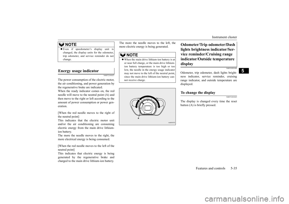
N00572101037
The power consumption of the electric motor, the air conditioning, and power generation by the regenerative brake are indicated. When the ready indicator comes on, the redneedle will move to th
e neutral point (A) and
then move to the right or left according to the amount of power consumption or power gen-eration. [When the red needle moves to the right of the neutral point] This indicates that the electric motor unitand/or the air conditioning are consuming electric energy from the main drive lithium- ion battery.The more the needle moves to the right, the more electrical energy
is being consumed.
[When the red needle moves to the left of the neutral point]This indicates that electric energy is being generated by the regenerative brake and charged to the main dr
ive lithium-ion battery.
The more the needle moves to the left, the more electric energy is being generated.
N00519501449
Odometer, trip odometer
, dash lights bright-
ness indicator, serv
ice reminder, cruising
range indicator, and outside temperature are displayed.
N00572201025
The display is changed every time the reset button (A) is briefly pressed.
NOTE
Even if speedometer
’s display unit is
changed, the display units for the odometer,trip odometer, and service reminder do notchange.
Energy usage indicator
NOTE
When the main drive lithium-ion battery is at or near full charge, or
the main drive lithium-
ion battery temperature is too high or too low, the needle in the energy usage indicatormay not move to the left of the neutral point, since the main drive lithium-ion battery can- not receive charge.
Odometer/Trip
odometer/Dash
lights brightness indicator/Ser-vice reminder/Cruising range indicator/Outside temperature display To change the display
BK0209800US.book 35 ページ 2014年1月14日 火曜日 午前9時26分
Page 144 of 262

Instrument cluster
Features and controls 5-39
5
N00573000010
This value (A) shows the outside temperature of the vehicle.
If the outside temperature drops below approximately 37 °F (3 °C), the alarm sounds and the outside air temperature warning indi- cator (B) flash for a
pproximately 10 seconds
to show there is a danger the road might be icy.
N00573100011
When the electric motor switch is in the “ACC” or “ON” position,
pressing the selec-
tor button (A) for more than 2 seconds will switch the outside temperature unit between °F and °C.
NOTE
The cruising range is
displayed based on the
past drive data. It ma
y vary depending on the
driving condition (roa
d condition, driving
situation, etc.) and
air conditioning operation
status. For example, the cruising range can be short-ened by driving on congested roads, by driv- ing uphill, by repeated ha
rd acceleration, and
by use of the air c
onditioner and heater.
When the 12V starter battery terminal is dis- connected, the power
consumption data of
the main drive lithium-ion battery in the pastis deleted. A different
value from before may
be displayed. Be sure
to use the display only
for reference. When the main drive lithium-ion battery is charged, the approximate cruising range isupdated.
Outside temperature display
NOTE
The outside temperatur
e can be displayed
from -40 °F (-40 °C) to 122 °F (50 °C). When the outside temperature is over 122 °F (50 °C) or below -40 °F (-40 °C), the displaywill remain 122 °F (50 °C) or -40 °F (-40 °C). The outside temperatur
e displayed may dif-
fer from the actual temperature on account of surrounding conditions,
driving conditions,
etc.
CAUTION Even when the outside air temperature warn- ing indicator (B) indica
tions do not flash, the
road may be icy, so please take care when driving.
Change of the outside temperature unit
BK0209800US.book 39 ページ 2014年1月14日 火曜日 午前9時26分
Page 145 of 262

Instrument cluster 5-40 Features and controls
5
N00572800024
The energy level gauge indicates the remain- ing power in the main drive lithium-ion bat- tery during charging or when the electric motor switch is in the “ON” position.
N00572900025
When the electric motor switch is in the“ON” position and the remaining bar of theenergy level gauge shows 2 bars or less, the warning indicator (A) and the charging bars (B) flash as follows: When the energy level gauge shows 2 bars: The warning indicator flashes. When the energy level gauge shows 1 bar: The warning indicator and the charging barsflash alternately. Recharge the main drive lithium-ion battery as soon as possible.
NOTE
Disconnecting the batter
y cable causes the
outside temperature unit memory to beerased. If it has been disconnected, readjust the unit with the above procedure.
Energy level gauge
F- Battery is fully charged. E- Charge the battery.
NOTE
The charging indicator is also illuminated during charging.Refer to “Charging i
ndicator” on page 5-42.
Low energy warning indicator
NOTE
If the energy level gauge shows 0 bars during use of the air conditioning, the cooling or heating may stop opera
tion and the mode is
changed to fan only. If the energy level gauge shows 0 bars, the power down warning light
is illuminated to
control the output. If the energy level gauge shows 2 bars while the main drive lithium-ion battery is being charged, the warning i
ndicator flashes. If the
energy level gauge shows 1 bar while the main drive lithium-ion battery is being charged, the warning indicator and the charg-ing bars flash alternately.
BK0209800US.book 40 ページ 2014年1月14日 火曜日 午前9時26分
Page 149 of 262

Combination headlights and dimmer switch 5-44 Features and controls
5
If the warning light illuminates when the out- side air temperature is very low, move thevehicle to a warmer location. If the warning light illuminates after the vehi- cle has been driven continuously uphill orwhen the outside air te
mperature is very high,
stop the vehicle in a safe place so the electric motor unit and/or the main drive lithium-ionbattery can cool down. When they have cooled down, the warni
ng light will go off. If
the warning light does not
turn off, contact a
certified i-MiEV dealer.
N00522501805
Rotate the switch to operate the lights.
The combinations of
switch operations and
illuminated lights differ in accordance withthe following conditions. [When the ready indicato
r is illuminated, and
the parking brake is released] The daytime running lights will be illumi- nated:
When temperature of the electric motor unit or the main drive lithium-ionbattery is too high or too low. When voltage of the main drive lithium-ion battery becomes low.
If the energy level gaugeshows 0 bar, the main drive lithium-ion battery is near empty and must be charged as soon as possible. Refer to “Charging” on page 3-11.
NOTE
When the power down warning light illumi- nates, avoid rapid st
arts and aggressive
acceleration.
Illumination of the
power down warning
light does not indica
te a malfunction.
If the power down warn
ing light illuminates
while the air conditioning is used, the cool- ing or heating may stop operating and onlythe fan will operate.
Combination headlights and dimmer switch Headlights
NOTE
Do not leave the head
lights and ot
her lights
on for a long period of time while the readyindicator is not illum
inated. A run down 12V
starter battery
could result.
When it rains, or wh
en the vehicle has been
washed, the inside of the lens sometimes becomes foggy. This is the same as whenwindow glass mists up
on a humid day, and
does not indicate a problem. When the light is switched on, the heat
will dry out the fog.
However, if water collects inside the light,have it checked by a certified i-MiEV dealer.NOTE
OFF
The daytime running lights illumi- nated
AUTO
The daytime running lights illumi- nated Headlights and other lights turn on and off automatically in accor-dance with outside light level.
BK0209800US.book 44 ページ 2014年1月14日 火曜日 午前9時26分