air condition MITSUBISHI iMiEV 2015 (in English) Owner's Guide
[x] Cancel search | Manufacturer: MITSUBISHI, Model Year: 2015, Model line: iMiEV, Model: MITSUBISHI iMiEV 2015Pages: 262, PDF Size: 26.84 MB
Page 183 of 262

Important air condit
ioning operating tips
7-10 Comfort controls
7
2. Set the mode select
ion dial to the “ ”
position. 3. Turn the temperature control dial clock-wise or counterclockw
ise to the desired
temperature between middle (
) and “H”
position.4. Select the desi
red blower speed.
5. Push the air conditioning switch (B). For quick defrosting 1. Set the mode selection dial to the “ ” position. 2. Turn the temperature control dial clock- wise or counterclockw
ise to the desired
temperature between middle (
) and “H”
position. 3. Press the MAX switch (A).
N00733700323
1. Park the vehicle in the shade whenever possible. Parking in the hot sun makes thevehicle interior extremely hot which then requires more time to cool. If it is neces- sary to park in the sun, open the windowsfor the first few minutes of air condition- ing to expel the hot air. 2. Afterwards, keep the windows closedwhen the air conditioning is in use. The entry of outside air through open windows will reduce cooling efficiency.
3. When running the air conditioning, make sure the air intake, which is located infront of the windshield, is free of obstruc- tions such as leaves. Leaves collected in the air-intake chamber may reduce airflow and plug the water drains.
If the air conditioning seems less effective than usual, the cause might be a refrigerant leak. Have the system inspected by a certified i-MiEV dealer.
NOTE
When the mode selection dial is set to the “ ” position, the air conditioning com- pressor runs automatically. Outside air intro-duction will also be se
lected automatically.
When defrosting, do not set the temperature control dial to the
maximum cool position.
This would blow c
ool air on the window
glass and fog it up. Since defogging or defrosting with the MAX switch consumes a la
rge amount of power,
stop the switch after
defogging or defrosting.
Use the MAX setting for a long time decreases the cruising range.
Important air conditioning operating tips
Air conditioning system refrig- erant and lubricant recommen- dations
BK0209800US.book 10 ページ 2014年1月14日 火曜日 午前9時26分
Page 184 of 262

Air purifier
Comfort controls 7-11
7
The air conditioning should be operated for at least five minutes each week, even in cold weather. This includes the quick defrostingmode. Operating the
air condition system
weekly maintains lubrication of the compres- sor internal parts and maintains the air condi-tioning in the best operating condition.
N00733800177
The air conditioning system is equipped with an air filter to reduc
e pollen and dust entering
the cabin.The air filter’s ability to collect pollen and dust will be reduced as
it becomes dirty, so
replace it periodically. For the maintenanceinterval, refer to the “WARRANTY AND MAINTENANCE MANUAL”.
N00766600016
You can run the air conditioning in advance of using the vehicle. For details, refer to“Remote Climate Control” on page 3-43.
N00734302128
The audio system can only be used when the electric motor switch is in the “ON” or “ACC” position.
CAUTION The air conditioning system in your vehicle must be charged with the refrigerant HFC-134a and the lubricant POE MA68EV.Use of any other refrigerant or lubricant will cause severe damage a
nd may require replac-
ing your vehicle’s en
tire air conditioning
system. The release of refrigerant into the atmo- sphere is not recommended.The new refrigerant HFC-134a in your vehi- cle is designed not to harm the earth’s ozone layer. However, it may contribute slightly toglobal warming. It is recommended that the old refrigerant be saved and recycled for future use.
During a long period of disuse
Air purifier
NOTE
Operation in certain conditions such as driv- ing on a dusty road or frequent use of the air conditioning can reduce
the service life of
the filter. When you feel that the air flow is lower than normal or when the windshield or windows start to fog up easily, replace the airfilter. Contact a certified i-MiEV dealer for assis- tance.
Remote Climate Control
(if so
equipped)
AM/FM electronically tuned radio with CD player
NOTE
To listen to the audio system while the elec- tric motor unit is not running, turn the elec- tric motor switch to the “ACC” position. If the electric motor switch is in the “ACC”position, the accessory power will automati- cally turn off after a certain period of time and you will no longer be able to use theaudio system. The accessory power comes on again if the electric motor switch is turned from the “ACC” position. Refer to “ACCpower auto-cutout f
unction” on page 5-19.
If a cellular phone is
used inside the vehicle,
it may create noise in the audio equipment. This does not mean that anything is wrong with your audio equipment. In such a case,use the cellular phone at
a place as
far away
as possible from the audio equipment. If foreign objects or wa
ter get into the audio
equipment, or if smoke or a strange odor comes from it, immediately turn off theaudio system and have
it checked at a certi-
fied i-MiEV dealer. Never try to repair it yourself. Avoid using the audio system untilit is inspected by a qualified person.
BK0209800US.book 11 ページ 2014年1月14日 火曜日 午前9時26分
Page 198 of 262

8
For emergenciesIf the vehicle breaks down ...............................................................8-2 Jump-starting ...................................................................................8-2 Tire repair kit ...................................................................................8-5Towing ...........................................................................................8-12 Operation under adverse driving conditions
...........
.........
.........
.....8-13
BK0209800US.book 1 ページ 2014年1月14日 火曜日 午前9時26分
Page 204 of 262

Tire repair kit
For emergencies 8-7
8
1. Park the vehicle on a
safe, flat and level
place. 2. Set the parking brake firmly. 3. Move the selector
lever to the “P”
(PARK) position and turn the electric motor switch to the “LOCK” position. 4. Turn on the hazard warning flashers andset up a warning sign, such as a warning triangle or flashing signal lamp, at an ade- quate distance from the vehicle, and haveall your passengers leave the vehicle. 5. Take out the tire repair kit.
6. Shake the tire sealant bottle well.
WA R N I N G The tire sealant can
cause health damage
if swallowed. If you
accidentally swallow
it, drink as much water as possible and immediately seek medical attention. If the tire sealant gets in your eyes or on your skin, rinse it away with lots of water. If you still sense an
abnormality, seek
medical attention. Consult a doctor immediately if any aller- gic reactions occur. Do not allow children to touch the tire sealant.CAUTION If the vehicle body is contaminated by the tire sealant, wipe the tire sealant off immedi- ately with a wet cloth. Immediately wash clothes contaminated with tire sealant.
NOTE
Do not pull out an object, such as a nail or screw, that penetrat
es the punctured tire.
Move the vehicle so that the tire valve is positioned away from the point where the tire touches the ground. If the valve is nearthe point where the tire touches the ground, the sealant may not enter the tire easily.
NOTE
In cold conditions (when the ambient tem- perature is 32 °F {0 °C} or lower), thicken- ing of the tire sealan
t can make the tire
sealant hard to squeeze out of the bottle. Warm the bottle between your hands inside the vehicle.
BK0209800US.book 7 ページ 2014年1月14日 火曜日 午前9時26分
Page 208 of 262

Tire repair kit
For emergencies 8-11
8
18. When you have inflated the tire to the
specified pressure, stow the compressor,bottle, and other item
s in the vehicle and
make sure that the seat cushion is properly secured. (Refer to “Tire repair kit storage”on page 8-5.) Promptly start driving the vehicle so that the tire sealant can spread evenly in the tire. Drive with great care.Do not exceed a speed of 50 mph (80 km/h). Observe local speed limits.
19. After driving for 10 minutes or 3 miles (5
km), park the vehicle in safe place.Remove the air compressor from the stowed position. Check the tire pressure using the air pressure gauge on the com-pressor. If the tire pressure has apparently not dropped, the emergency repair proce- dure is complete. Continue the processfrom step 21. If the tire pressure is not sufficient, inflate the tire to the specified pressure again and drive the vehicle carefully without exceeding a speed of 50 mph (80 km/h).Before driving, stow
the compressor and
make sure that the rear seat cushion is properly secured.
20. After driving for 10 minutes or 3 miles (5
km) again, check the tire pressure usingthe air pressure gauge on the compressor. If the tire pressure has apparently not dropped, the emergency repair procedureis complete. Before driving, make sure that the compressor is stowed and the seat cushion is properly secured. You muststill not exceed a speed of 50 mph (80 km/h). Observe local speed limits.
CAUTION If you sense any abnormality while driving, stop the vehicle and c
ontact a certified i-
MiEV dealer. Otherwise the tire pressure may drop before the em
ergency repair proce-
dure is completed,
rendering the vehicle
unsafe to drive.
CAUTION If the tire pressure is lower than the mini- mum permitted pressure
(18 psi {130 kPa}),
the tire cannot successful
ly be repaired with
the tire sealant. Do not drive the vehicle any further. Contact a certified i-MiEV dealer.
NOTE
If the tire pressure has dropped below the specified level when you check it at the endof the repair procedure, do not drive the vehicle any further.
Contact a certified i-
MiEV dealer. In cold conditions (when the ambient tem- perature is 32 °F {0 °C} or lower), the timeand driving distance
necessary unt
il comple-
tion of the repair can become longer than in warmer conditions, and th
e tire pressure may
drop below the specified level even after you have inflated the tire
the second time and
subsequently driven the
vehicle. If this hap-
pens, inflate the tire to the specified pressure once more, drive for about 10 minutes or 3 miles (5 km), then check the tire pressureagain. If the tire pressure has again dropped below the specified level, stop driving the vehicle and contact a certified i-MiEVdealer.
BK0209800US.book 11 ページ 2014年1月14日 火曜日 午前9時26分
Page 213 of 262

Service precautions 9-2 Vehicle care and maintenance
9
N00937301414
Taking regular care of your vehicle helps pre- serve its value and appe
arance as long as pos-
sible.This vehicle is an electric vehicle and is equipped with many high-voltage compo- nents. Refer to “High-voltage components”on page 3-30. You can do some of the maintenance work described in this manual by yourself, but the rest must be performed
only by a certified i-
MiEV dealer.If you discover a malfunction or other prob- lem, have it corrected by a certified i-MiEV dealer.Also follow the instru
ctions and take note of
the precautions for each procedure.
High voltage components and wiring cables are located as shown in the figure below.
Service precautions
WA R N I N G Never touch, remove or disassemble the high- voltage componen
ts including high-
voltage wires colore
d orange and their
connectors. Doing so can result in a fire, property damage, elec
trocution and seri-
ous injury or death. These components are affixed with a label indicating precautions for handling. Fol-low the instructions on the label. Take your vehicle to a cert
ified i-MiEV dealer
for any necessary maintenance.
1- Regular charge port 2- MCU 3- Main drive lithium-ion battery4- Heater 5- Air conditioner compressor 6- High voltage connector7- Service plug 8- Electric motor (Electric motor unit) 9- On board charger/DC-DC converter10- Quick charge port
WA R N I N G When servicing the vehicle, make sure that the electric motor switch is in the“LOCK” position and
the charging cable
is disconnected. Failure to do so could result in an electric shock.
When checking or servicing under the hood or the coolant reserve tank, be surethe electric motor unit is stopped and ithas had a chance to cool down. If you need to work
under the hood with
the electric motor unit on, be careful that your clothing, hair, etc. does not get caught in the fan or other moving parts. The fan can turn on automatically even if the electric motor unit is not running.Turn the electric motor switch to the “LOCK” position to be
safe while you are
working under the hood. Do not smoke or allow open flames around the 12V starter battery. Be extremely careful when working around the 12V starter battery. It containspoisonous and corros
ive sulfuric acid.
Handling your vehicle’s parts and materi- als in the wrong way can injure you. Ask a certified i-MiEV dealer
if you have ques-
tions. CAUTION The components inside
the electric motor
unit room may be very
hot to the touch.
Make sure all components have sufficientlycooled before beginning an inspection. These components are affixed with a label indicating precautions
for handling. Follow
the instructions on the label.WA R N I N G
BK0209800US.book 2 ページ 2014年1月14日 火曜日 午前9時26分
Page 231 of 262
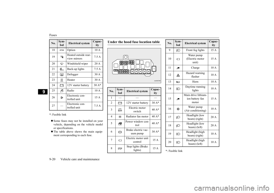
Fuses 9-20 Vehicle care and maintenance
9
* : Fusible link Some fuses may not be installed on your vehicle, depending on the vehicle model or specifications. The table above shows the main equip- ment corresponding to each fuse.
* : Fusible link
18 Option 10 A 19
Heated outside rear- view mirrors
7.5 A
20 Windshield wiper 20 A 21 Back-up lights 7.5 A 22 Defogger 30 A23 Heater 30 A24 12V starter battery 30 A
*
25 Radio 10 A 26
Electronic con- trolled unit
15 A
27 —
Electronic con- trolled unit
7.5 A
No.
Sym- bol
Electrical system
Capac-ity
Under the hood fuse location table No.
Sym- bol
Electrical system
Capac-ity
1— — — 2 12V starter battery 30 A
*
3
Electric motor
switch
40 A
*
4 Radiator fan motor 40 A
*
5
Power window con-
trol
40 A
*
6
Brake electric vac-
uum pump
30 A
*
7
Electric motor unit
control
15 A
8
Stop lights (Brake
lights)
15 A
9 Front fog lights 15 A 10
Water pump (Electric motor
unit)
15 A
11 Charge 10 A 12
Hazard warning
flasher
10 A
13 Horn 10 A 14
Daytime running
lights
10 A
15
Main drive lithium- ion battery fan
motor
15 A
16
Water pump
(Air conditioning)
10 A
17
Headlight (low beam) (right)
20 A
18
Headlight (low beam) (left)
20 A
19
Headlight (high beam) (right)
10 A
20
Headlight (high beam) (left)
10 A
No.
Sym- bol
Electrical system
Capac-ity
BK0209800US.book 20 ページ 2014年1月14日 火曜日 午前9時26分
Page 251 of 262

Vehicle labeling 11-2 Specifications
11
N01147400739
Keep a record of the chassis number and vehicle identification
number. This informa-
tion will assist the pol
ice if your vehicle is
ever stolen. The vehicle emission control information label is affixed in th
e location shown in the
illustration.
The vehicle identificati
on number is stamped
in the location shown in the illustration. It is visible from outside of the vehicle throughthe windshield. The air conditioning label is affixed on the bulkhead as shown in the illustration.
The vehicle information
code plate is located
on the driver’s door sill. The chassis number is stamped behind the lid on the right side of the luggage room.
Vehicle labeling 1 - Vehicle emission control information label
2 - Vehicle identification num- ber plate 3 - Air conditioning label
4 - Vehicle information code plate Chassis number
BK0209800US.book 2 ページ 2014年1月14日 火曜日 午前9時26分
Page 255 of 262

Refill capacities 11-6 Specifications
11
N01148001003
* : similar high quality ethylene
glycol based non-silicate, non-
amine, non-nitrate and non-borate
coolant with long life hybrid
organic acid tech-
nology These tires satisfy vehicle loading condit
ions described in th
is owner’s manual.
Refill capacities No.
Item
Capacity
Lubricants
1
Windshield washer fluid 2.0 qt (1.9 L) —
2
Brake As required Conforming to Brake fluid DOT 3 or DOT 4
3
Hot water heater fluid [Includes .42 qt (0.4 L) in reservoir]
2.0 qt (1.9 L)
Mitsubishi Motors Genui
ne Super Long Life
Coolant Premium or
an equivalent
*
4
Coolant [Includes 1.2 qt (1.1 L) in reservoir]
5.4 qt (5.1 L)
5
Transmission .79 qt (0.75 L) Mits
ubishi Motors Genuine ATF SP III
6
Refrigerant (air
conditioning)
Refer to the “Air con- ditioning label” on
page 11-2
HFC-134a
NOTE
BK0209800US.book 6 ページ 2014年1月14日 火曜日 午前9時26分
Page 256 of 262

Alphabetical index
12-1
12
Numerics
12V power outlet
................................
5-51
12V starter battery
................................
9-7
Specification
..................................
11-5
12V starter battery charging system warning light
.................................................
5-43
A
Accessory (installation)
.........................
3-6
Acoustic vehicle alerting system (AVAS)
....
5-23 Active stability control
........................
5-28
ASC indicator
.................................
5-30
ASC OFF indicator
.........................
5-30
ASC OFF switch
............................
5-29
Skid control function
.......................
5-29
Traction control function
.................
5-29
Air conditioning
...................................
7-4
Important air condi
tioning operating tips
..
7-10
Air purifier
.........................................
7-11
Aluminum wheels
...............................
9-32
Antenna
.............................................
7-22
Anti-lock braking system
.....................
5-25
Warning light
........................
5-26
, 5-27
ASC
..................................................
5-28
ASC indicator
.....................................
5-30
ASC OFF indicator
.............................
5-30
ASC OFF switch
................................
5-29
Assist grip
.........................................
5-56
Audio
AM/FM electronicall
y tuned radio with
CD player
....................................
7-11
Error codes
....................................
7-19
Handling of compact discs
..............
7-20
B
Back up lights
Bulb capacity
.................................
9-22
Replacement
..................................
9-25
Ball joint, steering li
nkage seals and drive
shaft boots
.......................................
9-17
Battery
12V starter battery charging system warn- ing light
.......................................
5-43
Disconnection and connection
...........
9-9
During cold weather
.........................
9-9
Main drive lithium-ion battery
...........
3-3
Brake
Anti-lock braking system
................
5-25
Braking
...........................................
6-5
Fluid
.......................................
9-7
, 11-6
Hose
.............................................
9-17
Parking brake
.................................
5-16
Parking brake lever stroke
...............
9-16
Pedal
.............................................
5-24
Pedal free play
...............................
9-16
Power brakes
..................................
5-24
Service brake
..................................
5-24
Warning light
.................................
5-42
Brake assist system
.............................
5-25
Break-in recommendations
....................
5-2
Bulb capacity
......................................
9-22
C
California Perchl
orate Materials
Requirements
.....................................
3-7
Capacities
..........................................
11-6
Card holder
...............................
5-51
, 5-55
Cargo loads
........................................
6-10
Certification label
...............................
11-3
Charging
Quick charging
...............................
3-24
Regular charging
...................
3-15
, 3-24
Charging indicator
..............................
5-42
Charging Timer
..................................
3-36
Charging troubleshooting guide
............
3-28
Chassis number
...................................
11-2
Child restraint
.....................................
4-13
Child safety locks for rear door
............
5-10
Cleaning
Inside of your vehicle
......................
9-29
Outside of your vehicle
...................
9-30
Clock
.................................................
7-22
BK0209800US.book 1 ページ 2014年1月14日 火曜日 午前9時26分