high beam MITSUBISHI L200 2011 Owner's Manual (in English)
[x] Cancel search | Manufacturer: MITSUBISHI, Model Year: 2011, Model line: L200, Model: MITSUBISHI L200 2011Pages: 330, PDF Size: 22.34 MB
Page 92 of 330
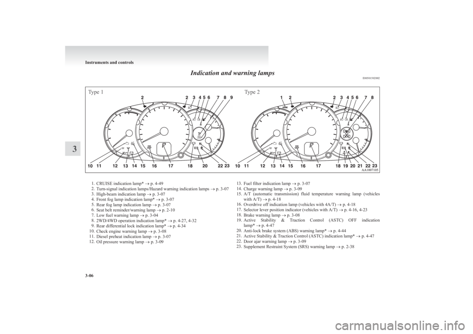
Indication and warning lampsE00501502002
Type 1Type 21.CRUISE indication lamp* ® p. 4-49
2. Turn-signal indication lamps/Hazard warning indication lamps ® p. 3-07
3. High-beam indication lamp ® p. 3-07
4. Front fog lamp indication lamp* ® p. 3-07
5. Rear fog lamp indication lamp ® p. 3-07
6. Seat belt reminder/warning lamp ® p. 2-10
7. Low fuel warning lamp ® p. 3-04
8. 2WD/4WD operation indication lamp* ® p. 4-27, 4-32
9. Rear differential lock indication lamp* ® p. 4-34
10. Check engine warning lamp ® p. 3-08
11. Diesel preheat indication lamp ® p. 3-07
12. Oil pressure warning lamp ® p. 3-0913.
Fuel filter indication lamp ® p. 3-07
14. Charge warning lamp ® p. 3-09
15. A/T (automatic transmission) fluid temperature warning lamp (vehicles
with A/T) ® p. 4-18
16. Overdrive off indication lamp (vehicles with 4A/T) ® p. 4-18
17. Selector lever position indicator (vehicles with A/T) ® p. 4-16, 4-23
18. Brake warning lamp ® p. 3-08
19. Active Stability & Traction Control (ASTC) OFF indication
lamp* ® p. 4-47
20. Anti-lock brake system (ABS) warning lamp* ® p. 4-44
21. Active Stability & Traction Control (ASTC) indication lamp* ® p. 4-47
22. Door ajar warning lamp ® p. 3-09
23. Supplement Restraint System (SRS) warning lamp ® p. 2-38
Instruments and controls
3-06
3
Page 93 of 330
Indication lampsE00501600012Turn-signal indication lamps/
Hazard warning indication
lamps E00501700185
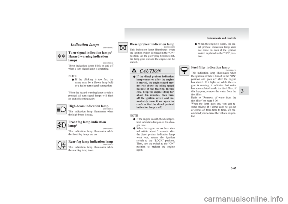
These indication lamps blink on and off
when a turn-signal lamp is operating.
NOTE l If the blinking is too fast, the
cause may be a blown lamp bulb
or a faulty turn-signal connection.
When the hazard warning lamp switch is
pressed, all turn-signal lamps will flash
on and off continuously.High-beam indication lamp E00501800115
This indication lamp illuminates when
the high-beam is used.Front fog lamp indication
lamp* E00501900347
This indication lamp illuminates while
the front fog lamps are on.Rear fog lamp indication lamp E00502000114
This indication lamp illuminates while
the rear fog lamp is on.Diesel preheat indication lamp E00502300250
This indication lamp illuminates when
the ignition switch is placed in the “ON”
position. As the glow plug becomes hot,
the lamp goes out and the engine can be
started.CAUTIONl If the diesel preheat indication
lamp comes on after the engine
is started, the engine speed may
not rise above the idling speed
because of fuel freezing. In this
case, keep the engine idling for
about ten minutes, then turn
off the ignition switch and im-
mediately turn it on again to
confirm that the diesel preheat
indication lamp is off.
NOTE
l If the engine is cold, the diesel pre-
heat indication lamp is on for a lon-
ger time.
l When the engine has not been star-
ted within about 5 seconds after
the diesel preheat indication lamp
went out, return the ignition
switch to the “LOCK” position.
Then, turn the switch to the “ON”
position to preheat the engine
again.
l When the engine is warm, the die-
sel preheat indication lamp does
not come on even if the ignition
switch is placed in the “ON” posi-
tion.Fuel filter indication lamp E00509900170
This indication lamp illuminates when
the ignition switch is turned to the “ON”
position and goes off after the engine
has started. If it lights up while the en-
gine is running, it indicates that water
has accumulated inside the fuel filter; if
this happens, remove the water from the
fuel filter.
Refer to “Removal of water from the
fuel filter” on page 6-06.
When the lamp goes out, you can re-
sume driving. If it either does not go out
or comes on from time to time, we rec-
ommend you to have the vehicle inspec-
ted.
Instruments and controls
3-07
3
Page 117 of 330
lIf the lamps do not turn on or off with the
switch in the “AUTO” position, manually op-
erate the switch and we recommend you to
have your vehicle checked.
[Vehicles with Daytime Running Lamp]
When the ignition switch is in the “ON” position
and the lamp switch is set to the “OFF” position,
the low beam of the headlamps, tail lamps, etc.,
will illuminate.
Lamps (headlamps, fog lamp, etc.) au-
to-cutout function
l If the key is turned to the “LOCK” or
“ACC” position or removed from the igni-
tion switch and the lamps will stay on for
about 3 minutes without opening the driver’s
door while the lamp switch in the “
” posi-
tion, the lamps automatically turn off.
l If the key is turned to the “LOCK” or
“ACC” position or removed from the igni-
tion switch and the driver’s door is opened
within 3 minutes while the lamp switch in
the “
” position, a buzzer will sound to
warn the driver that the lamps have not been
turned off, and these lamps will automatical-
ly turn off.
NOTE l The lamp auto-cutout will not function when
the lamp switch is in the “
” position.
l When the ignition key has been turned to ei-
ther the “LOCK” or “ACC” position or re-
moved from the ignition switch with the
lamp switch in the “
” position, and the
lamp switch is returned to the “OFF” posi-
tion within approximately 3 minutes, the auto-
cutout function will not be activated.
When you want to keep the lamps on l Turn the switch in the “OFF” position to
switch off all lamps while the ignition key is
in the “LOCK” or “ACC” position or re-
move it from the ignition switch.
l Turn on the lamps with the switch in the
“
” or “” position again, then the
lamps will remain on.
NOTE l It is possible to alter the auto-cutout function
such that: • Auto-cutout function is never activated.
For details, we recommend you to consult a
MITSUBISHI MOTORS Authorized Service
Point.
Lamp monitor buzzer E00506100184
If the driver’s door is opened when the ignition key
is in the “LOCK” or “ACC” position or removed
from the ignition switch while the lamps are on, a
buzzer will sound to remind the driver to turn off
the lamps. When the lamp auto-cutout function
acts, the buzzer will stop automatically. When this
function does not act, turn off the lamp switch to
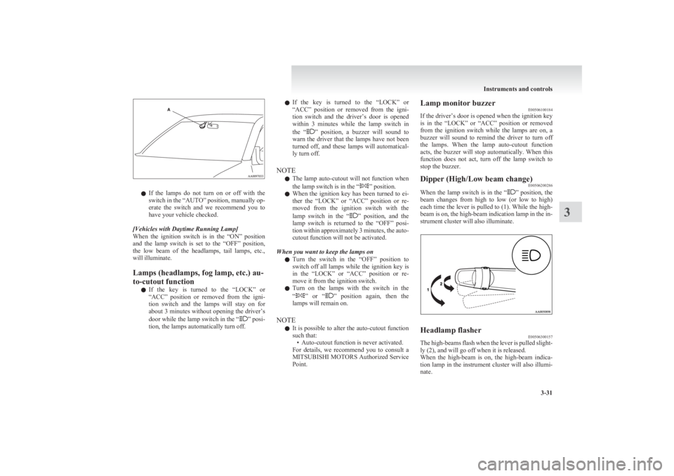
stop the buzzer.Dipper (High/Low beam change) E00506200286
When the lamp switch is in the “” position, the
beam changes from high to low (or low to high)
each time the lever is pulled to (1). While the high-
beam is on, the high-beam indication lamp in the in-
strument cluster will also illuminate.
Headlamp flasher E00506300157
The high-beams flash when the lever is pulled slight-
ly (2), and will go off when it is released.
When the high-beam is on, the high-beam indica-
tion lamp in the instrument cluster will also illumi-
nate.
Instruments and controls
3-31
3
Page 118 of 330
NOTEl The high-beams can also flash when the
lamp switch is in the “OFF” position.
l If you turn the lamps off with the headlamps
set to high-beam illumination, the headlamps
are automatically returned to their low-beam
setting when the lamp switch is next turned
to the “
” position.
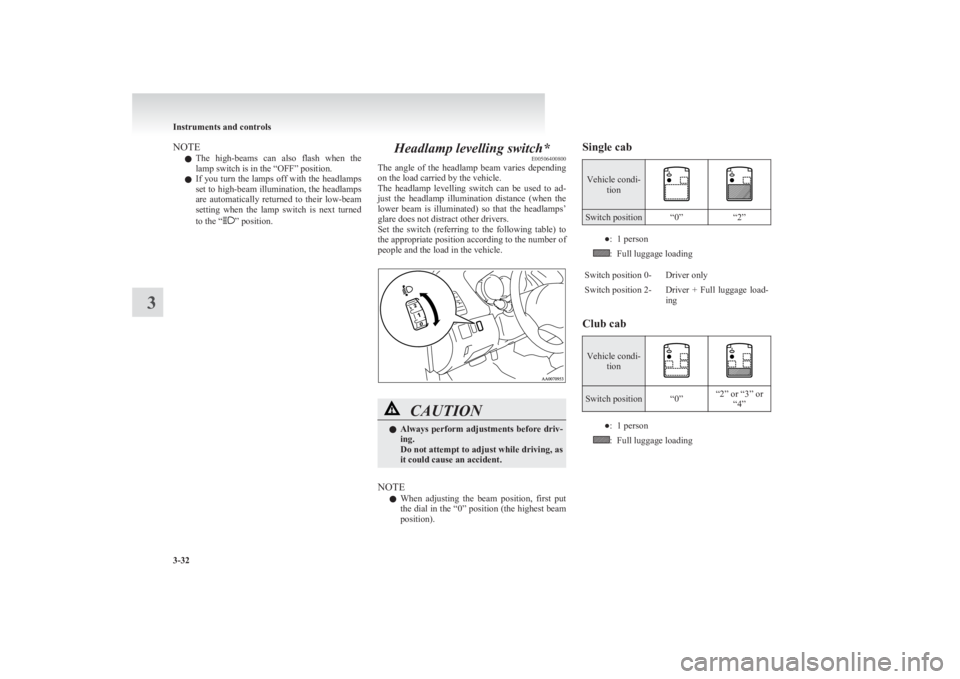
Headlamp levelling switch* E00506400800
The angle of the headlamp beam varies depending
on the load carried by the vehicle.
The headlamp levelling switch can be used to ad-
just the headlamp illumination distance (when the
lower beam is illuminated) so that the headlamps’
glare does not distract other drivers.
Set the switch (referring to the following table) to
the appropriate position according to the number of
people and the load in the vehicle.CAUTIONl Always perform adjustments before driv-
ing.
Do not attempt to adjust while driving, as
it could cause an accident.
NOTE
l When adjusting the beam position, first put
the dial in the “0” position (the highest beam
position).
Single cabVehicle condi- tion
Switch position“0”“2”●:1 person:Full luggage loadingSwitch position 0-Driver onlySwitch position 2-Driver + Full luggage load-
ing
Club cab
Vehicle condi- tionSwitch position“0”“2” or “3” or“4”●:1 person:Full luggage loading
Instruments and controls
3-32
3
Page 284 of 330
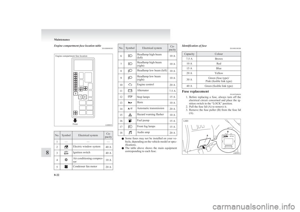
Engine compartment fuse location tableE01008000583Engine compartment fuse locationFront
No.SymbolElectrical systemCa-
pacity1———2Electric window system40 A3Ignition switch40 A4Air conditioning compres-
sor10 A5Condenser fan motor20 ANo.SymbolElectrical systemCa-
pacity6Headlamp high-beam
(left)10 A7Headlamp high-beam
(right)10 A8Headlamp low beam (left)10 A9Headlamp low beam
(right)10 A10Engine control20 A11Alternator7.5 A12Stop lamps15 A13Horn10 A14Automatic transmission20 A15Hazard warning flasher10 A16Fuel pump15 A17Front fog lamps15 A18Audio amp20 A
l Some fuses may not be installed on your ve-
hicle, depending on the vehicle model or spec-
ifications.
l The table above shows the main equipment
corresponding to each fuse.
Identification of fuse E01008100308CapacityColour7.5 ABrown10 ARed15 ABlue20 AYellow30 AGreen (fuse type)/
Pink (fusible link type)40 AGreen (fusible link type)Fuse replacement E01007800656
1.Before replacing a fuse, always turn off the
electrical circuit concerned and place the ig-
nition switch in the “LOCK” position.
2. Pull the fuse lid (A) to remove it.
3. Remove the fuse puller (B) from the fuse lid
(A).
Maintenance
8-22
8 LHD
Page 286 of 330
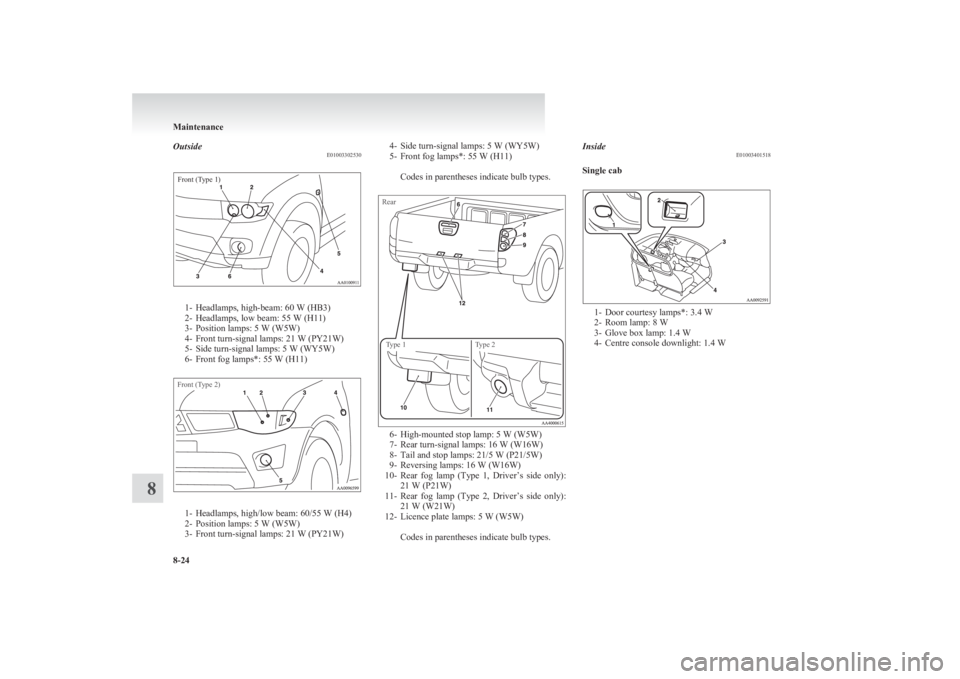
OutsideE01003302530Front (Type 1)
1- Headlamps, high-beam: 60 W (HB3)
2- Headlamps, low beam: 55 W (H11)
3- Position lamps: 5 W (W5W)
4- Front turn-signal lamps: 21 W (PY21W)
5- Side turn-signal lamps: 5 W (WY5W)
6- Front fog lamps*: 55 W (H11)
Front (Type 2)
1- Headlamps, high/low beam: 60/55 W (H4)
2- Position lamps: 5 W (W5W)
3- Front turn-signal lamps: 21 W (PY21W)
4- Side turn-signal lamps: 5 W (WY5W)
5- Front fog lamps*: 55 W (H11)
Codes in parentheses indicate bulb types.RearType 1Type 2
6- High-mounted stop lamp: 5 W (W5W)
7- Rear turn-signal lamps: 16 W (W16W)
8- Tail and stop lamps: 21/5 W (P21/5W)
9- Reversing lamps: 16 W (W16W)
10- Rear fog lamp (Type 1, Driver’s side only):
21 W (P21W)
11- Rear fog lamp (Type 2, Driver’s side only):
21 W (W21W)
12- Licence plate lamps: 5 W (W5W)
Codes in parentheses indicate bulb types.
Inside E01003401518
Single cab
1- Door courtesy lamps*: 3.4 W
2- Room lamp: 8 W
3- Glove box lamp: 1.4 W
4- Centre console downlight: 1.4 W
Maintenance
8-24
8
Page 287 of 330
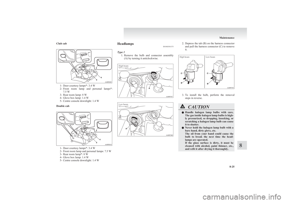
Club cab
1- Door courtesy lamps*: 3.4 W
2- Front room lamp and personal lamps*:
7.5 W
3- Rear room lamp: 8 W
4- Glove box lamp: 1.4 W
5- Centre console downlight: 1.4 W
Double cab
1- Door courtesy lamps*: 3.4 W
2- Front room lamp and personal lamps: 7.5 W
3- Rear room lamp*: 8 W
4- Glove box lamp: 1.4 W
5- Centre console downlight: 1.4 W
Headlamps E01003501375
Type 1 1.Remove the bulb and connector assembly
(A) by turning it anticlockwise.High beamLow beam2. Depress the tab (B) on the harness connector
and pull the harness connector (C) to remove
it.High beamLow beam
3. To install the bulb, perform the removal
steps in reverse.
CAUTIONl Handle halogen lamp bulbs with care.
The gas inside halogen lamp bulbs is high-
ly pressurized, so dropping, knocking, or
scratching a halogen lamp bulb can cause
it to shatter.
l Never hold the halogen lamp bulb with a
bare hand, dirty glove, etc.
The oil from your hand could cause the
bulb to break the next time the head-
lamps are operated.
If the glass surface is dirty, it must be
cleaned with alcohol, paint thinner, etc.,
and refit it after drying it thoroughly.
Maintenance
8-25
8
Page 321 of 330
4
4-wheel drive operation 4-38A
Accessory (Installation) 04
Accessory socket 5-38
Active Stability & Traction Control (ASTC) 4-46
Additional equipment 8-19
Air conditioning Automatic air conditioning 5-08
Important operation tips for the air condition-
ing 5-12
Manual air conditioning 5-03
Air purifier 5-12
Airbag 2-27
Antenna 5-34
Anti-lock brake system (ABS) 4-43 Warning lamp 4-44
Armrest (Double cab) 2-07
Ashtray 5-36
Audio Audio system anti-theft feature 5-32
Error codes 5-30
Handling of compact discs 5-32
LW/MW/FM electronic tuning radio with CD
player 5-13
Steering wheel remote control switch 5-28
Automatic air conditioning 5-08
Automatic transmission 4A/T 4-16 Fluid 8-06,9-21
Overdrive control switch 4-17
Selector lever operation 4-16,4-20
Selector lever position 4-17
Selector lever position indicator 4-16
Automatic transmission Sports Mode 5A/T 4-20 Fluid 8-06,9-21
Selector lever operation 4-20
Selector lever position indicator 4-21
Selector lever positions 4-21
Sports mode 4-22
Sports mode indicator 4-22
B
Battery 8-09Discharged battery (Emergency starting) 6-02
Specification 9-16
Bleeding the fuel system 6-05
Bonnet 8-03
Bottle holder 5-45
Brake Anti-lock brake 4-43
Braking 4-42
Fluid 8-07,9-21
Parking brake 4-07
Parking brake lever stroke 8-16
Pedal free play 8-16
Warning lamp 3-08
C
Cargo loads 4-52
Catalytic converter 8-02
Cautions on handling of 4-wheel drive vehi-
cles 4-40
Central door locks 1-07
Centre console downlight 5-41 Bulb capacity 8-24
Replacement 8-34
Centre information display 3-10
Changing a fuse 8-22
Changing gears 4-14
Check engine warning lamp 3-08
Child restraint 2-13
Child-protection rear doors 1-08
Cigarette lighter 5-37
Cleaning Exterior of your vehicle 7-03
Genuine leather 7-02
Interior of your vehicle 7-02
Plastic, vinyl leather, etc 7-02
Sunroof 7-05
Waxing 7-04
Clock 3-19,5-39
Clutch Fluid 8-08,9-21
Pedal free play 8-15
Coat hook 5-46
Combination headlamps and dipper switch 3-30
Convenient hook 5-46
Coolant (engine) 8-05,9-21
Cruise control 4-48 Switch 4-49
Cup holder 5-44
Curtain airbag system 2-35
D
Demister (rear window) 3-40
Differential oil 9-21
Digital clock 3-19,5-39
Dimensions 9-03
Dipper (High/Low beam change) 3-31
Door courtesy lamps 5-41 Replacement 8-33
Doors Central door locks 1-07
Child-protection 1-08
Lock and unlock 1-06
Driving, alcohol and drugs 4-02
E
Easy select 4WD 4-25
Alphabetical index
1