engine MITSUBISHI L200 2012 (in English) Repair Manual
[x] Cancel search | Manufacturer: MITSUBISHI, Model Year: 2012, Model line: L200, Model: MITSUBISHI L200 2012Pages: 370, PDF Size: 23.14 MB
Page 257 of 370
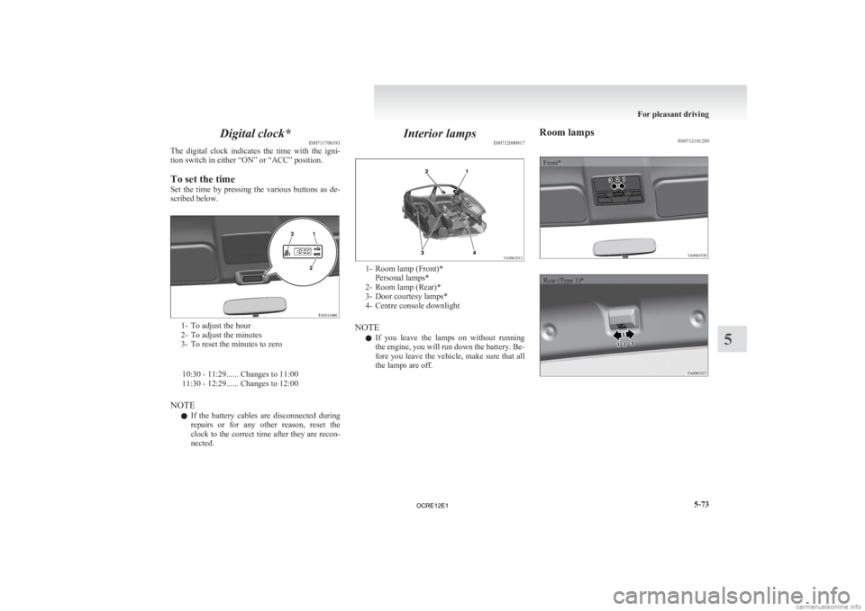
Digital clock*
E00711700193
The
digital clock indicates the time with the igni-
tion switch in either “ON” or “ACC” position.
To set the time
Set the time by pressing the various buttons as de-
scribed below. 1- To adjust the hour
2-
To adjust the minutes
3- To reset the minutes to zero
10:30 - 11:29...... Changes to 11:00
11:30 - 12:29...... Changes to 12:00
NOTE l If the battery cables are disconnected during
repairs or for any other reason, reset the
clock to the correct time after they are recon-
nected. Interior lamps
E00712000917 1- Room lamp (Front)*
Personal lamps*
2-
Room lamp (Rear)*
3- Door courtesy lamps*
4- Centre console downlight
NOTE l If you leave the lamps on without running
the engine, you will run down the battery. Be-
fore you leave the vehicle, make sure that all
the lamps are off. Room lamps
E00712101289
Front*
Rear (Type 1)* For pleasant driving
5-73 5
OCRE12E1
Page 267 of 370
If the vehicle breaks down
............................................................ 6-02
Emergency starting ....................................................................... 6-02
Engine overheating ....................................................................... 6-04
Bleeding the fuel system
...............................................................6-05
Removal of water from the fuel filter ...........................................6-06
Tools, jack and jack handle .......................................................... 6-07
Jacking up the vehicle...................................................................6-13
Spare wheel...................................................................................6-16
How to change a tyre .................................................................... 6-17
Towing.......................................................................................... 6-20
Operation under adverse driving conditions .................................6-24For emergencies
6
OCRE12E1
Page 268 of 370
If the vehicle breaks down
E00800101166
If
the vehicle breaks down on the road, move it to
the shoulder and use the hazard warning flashers and/
or the warning triangle etc.
Refer to “Hazard warning flasher switch” on page
3-34.
If the engine stops/fails
Vehicle operation and control are affected if the en-
gine stops.
Before moving the vehicle to a safe area, be aware
of the following:
l The brake booster becomes inoperative and
the pedal effort will increase. Press down the
brake pedal harder than usual.
l Since the power steering pump is no longer
operative, the steering wheel feels heavy
when turning it. Emergency starting
E00800502112
If
the engine cannot be started because the battery
is weak or dead, the battery from another vehicle
can be used with jumper cables to start the engine. WARNING
l To
start the engine using jumper cables
connected from another vehicle, perform
the correct procedures according to the in-
struction manual. Incorrect procedures
could result in a fire or explosion or dam-
age to the vehicles.
1. Get
the vehicles close enough so the jumper cables can reach, but be sure the vehicles
aren’t touching each other.
If they are, it could cause a ground connec-
tion you don’t want. The vehicle will not
start, and the bad grounding could damage
the electrical systems. CAUTION
l
Check
the other vehicle. It must have a 12-
volt battery.
If the other system isn’t 12-volt, shorting
can damage both vehicles.
2. You
could be injured if the vehicles move. Set the parking brake firmly on each vehicle.
Put an automatic transmission in “P”
(PARK) or a manual transmission in “N”
(Neutral). Turn off the ignition switch. WARNING
l Turn
off the ignition on both vehicles be-
forehand.
Make sure that the cables or your clothes
cannot be caught by the fan or drive belt.
Personal injury could result.
NOTE l Turn
off all lamps, heater and other electrical
loads. This will avoid sparks and help save
both batteries.
3. Make sure battery electrolyte is at the proper level.
Refer to “Battery” on page 8-10. WARNING
l If
electrolyte fluid is not visible, or ap-
pears to be frozen, Do Not Attempt Jump
Starting!
A battery might rupture or explode if the
temperature is below the freezing point
or if it is not filled to the proper level.
4. Connect
one end of one jumper cable to the positive (+) terminal of the discharged bat-
tery (A), and the other end to the positive (+)
terminal of the booster battery (B).
For emergencies
6-02
6
OCRE12E1
Page 269 of 370
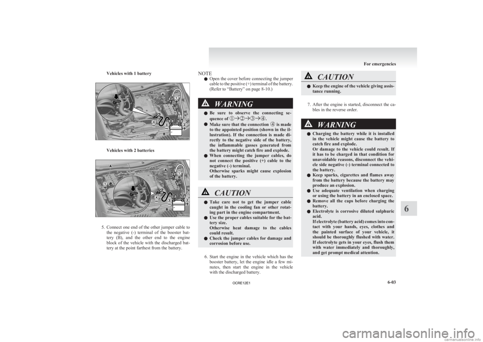
Vehicles with 1 battery
Vehicles with 2 batteries
5. Connect one end of the other jumper cable to
the negative (-) terminal of the booster bat-
tery (B), and the other end to the engine
block of the vehicle with the discharged bat-
tery at the point farthest from the battery. NOTE
l Open
the cover before connecting the jumper
cable to the positive (+) terminal of the battery.
(Refer to “Battery” on page 8-10.) WARNING
l Be
sure to observe the connecting se-
quence of .
l Make sure that the connection is made
to
the appointed position (shown in the il-
lustration). If the connection is made di-
rectly to the negative side of the battery,
the inflammable gasses generated from
the battery might catch fire and explode.
l When connecting the jumper cables, do
not connect the positive (+) cable to the
negative (-) terminal.
Otherwise sparks might cause explosion
of the battery. CAUTION
l
Take
care not to get the jumper cable
caught in the cooling fan or other rotat-
ing part in the engine compartment.
l Use the proper cables suitable for the bat-
tery size.
Otherwise heat damage to the cables
could result.
l Check the jumper cables for damage and
corrosion before use.
6. Start
the engine in the vehicle which has the booster battery, let the engine idle a few mi-
nutes, then start the engine in the vehicle
with the discharged battery. CAUTION
l
Keep
the engine of the vehicle giving assis-
tance running.
7. After
the engine is started, disconnect the ca- bles in the reverse order. WARNING
l Charging
the battery while it is installed
in the vehicle might cause the battery to
catch fire and explode.
Or damage to the vehicle could result. If
it has to be charged in that condition for
unavoidable reasons, disconnect the vehi-
cle side negative (-) terminal connected to
the battery.
l Keep sparks, cigarettes and flames away
from the battery because the battery may
produce an explosion.
l Use adequate ventilation when charging
or using the battery in an enclosed space.
l Remove all the caps before charging the
battery.
l Electrolyte is corrosive diluted sulphuric
acid.
If electrolyte (battery acid) comes into con-
tact with your hands, eyes, clothes and
the painted surface of your vehicle, it
should be thoroughly flushed with water.
If electrolyte gets in your eyes, flush them
with water immediately and thoroughly,
and get prompt medical attention. For emergencies
6-03 6
OCRE12E1
Page 270 of 370
CAUTION
l
Do not attempt to start the engine by pull-
ing or pushing the vehicle.
It could damage your vehicle.
l Always wear protective eye goggles when
working near the battery.
l Keep the battery out of the reach of chil-
dren.
NOTE l On
vehicles with anti-lock brake system, if
the vehicle is put in motion without fully
charging the battery, it might cause the loss
of smooth engine operation and the antilock
brake warning lamp to illuminate.
Refer to “Anti-lock brake system (ABS)” on
page 4-44. Engine overheating
E00800601985
If
the water temperature gauge indication remains
in the overheating zone for a long time, the engine
may be overheating. If this occurs, take the follow-
ing corrective measures: 1. Stop the vehicle in a safe place.
2. Check whether steam is coming from the en-gine compartment.
[If steam does not come from the engine com-
partment]
With the engine still running, raise the bon-
net to ventilate the engine compartment.
[If steam is coming from the engine compart-
ment]
Stop the engine, and when the steam stops,
raise the bonnet to ventilate the engine com-
partment. Restart the engine. WARNING
l Do
not open the bonnet while steam is com-
ing from the engine compartment. It
could cause steam or hot water to spurt
out, causing burns. Hot water could spurt
out even when there is no steam coming
out, and some parts will be very hot. Be
very careful when opening the bonnet.
l Be careful of hot steam, which could be
blowing off the reserve tank cap.
l Do not attempt to remove the radiator
cap while the engine is hot. 3. Confirm
that the cooling fan is turning. If the
fan is not turning, stop the engine immediate-
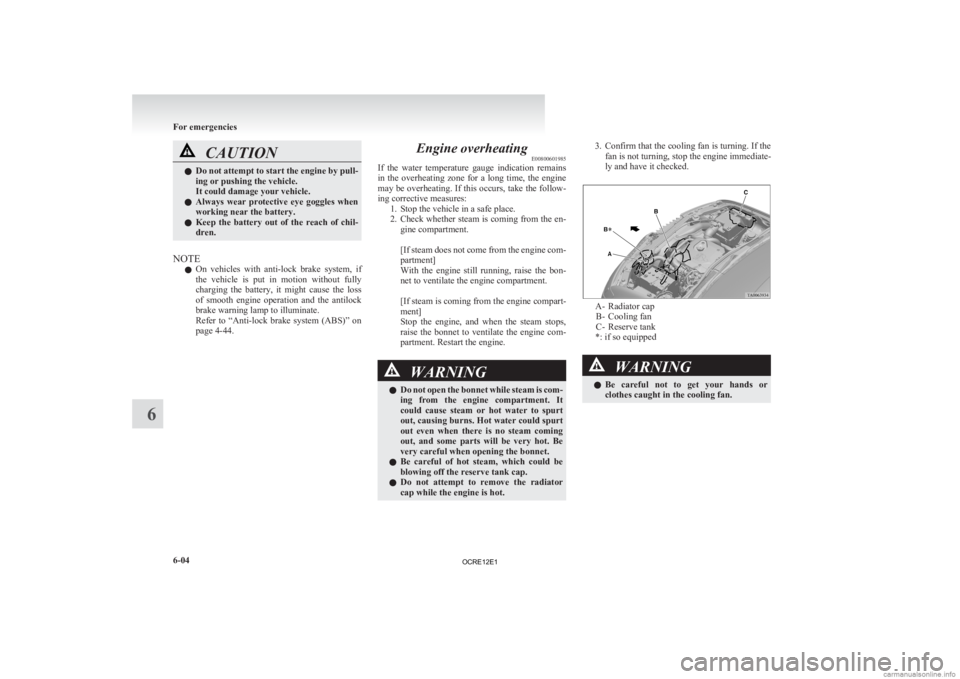
ly and have it checked. A- Radiator cap
B-
Cooling fan
C- Reserve tank
*: if so equipped WARNING
l Be
careful not to get your hands or
clothes caught in the cooling fan. For emergencies
6-04
6
OCRE12E1
Page 271 of 370
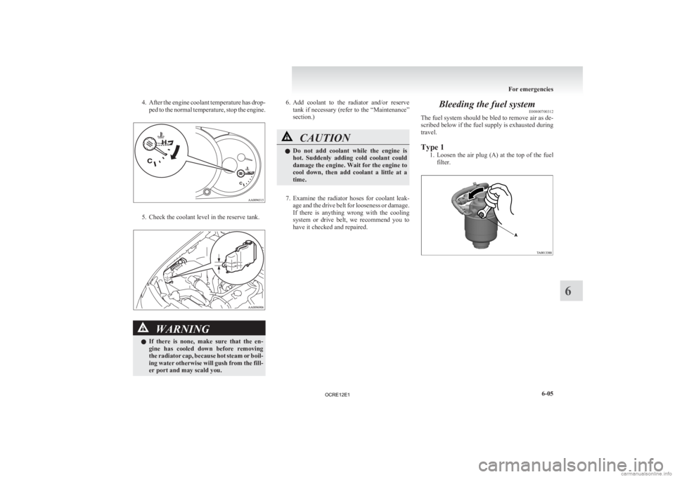
4. After the engine coolant temperature has drop-
ped to the normal temperature, stop the engine. 5. Check the coolant level in the reserve tank.
WARNING
l If
there is none, make sure that the en-
gine has cooled down before removing
the radiator cap, because hot steam or boil-
ing water otherwise will gush from the fill-
er port and may scald you. 6. Add
coolant to the radiator and/or reserve
tank if necessary (refer to the “Maintenance”
section.) CAUTION
l
Do
not add coolant while the engine is
hot. Suddenly adding cold coolant could
damage the engine. Wait for the engine to
cool down, then add coolant a little at a
time.
7. Examine
the radiator hoses for coolant leak- age and the drive belt for looseness or damage.
If there is anything wrong with the cooling
system or drive belt, we recommend you to
have it checked and repaired. Bleeding the fuel system
E00800700312
The fuel system should be bled to remove air as de-
scribed below if the fuel supply is exhausted during
travel.
Type 1
1. Loosen
the air plug (A) at the top of the fuel
filter. For emergencies
6-05 6
OCRE12E1
Page 272 of 370
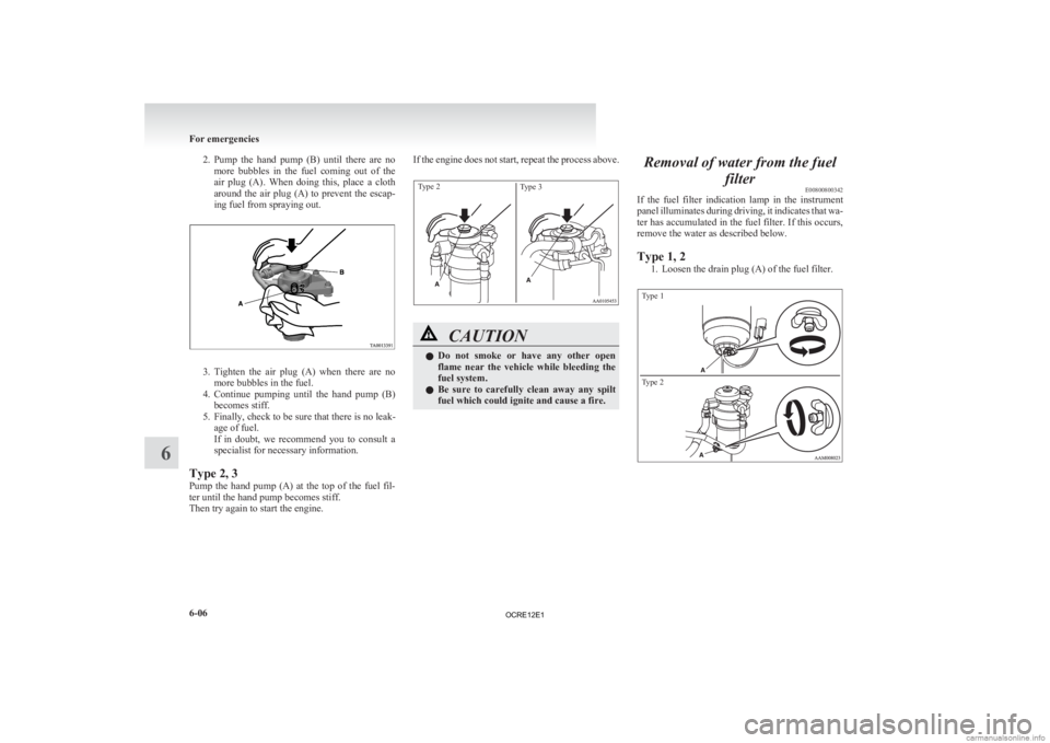
2. Pump the hand pump (B) until there are no
more bubbles in the fuel coming out of the
air plug (A). When doing this, place a cloth
around the air plug (A) to prevent the escap-
ing fuel from spraying out. 3. Tighten
the air plug (A) when there are no
more bubbles in the fuel.
4. Continue pumping until the hand pump (B) becomes stiff.
5. Finally, check to be sure that there is no leak- age of fuel.
If in doubt, we recommend you to consult a
specialist for necessary information.
Type 2, 3
Pump the hand pump (A) at the top of the fuel fil-
ter until the hand pump becomes stiff.
Then try again to start the engine. If the engine does not start, repeat the process above.
Type 2
Type 3 CAUTION
l
Do
not smoke or have any other open
flame near the vehicle while bleeding the
fuel system.
l Be sure to carefully clean away any spilt
fuel which could ignite and cause a fire. Removal of water from the fuel
filterE00800800342
If
the fuel filter indication lamp in the instrument
panel illuminates during driving, it indicates that wa-
ter has accumulated in the fuel filter. If this occurs,
remove the water as described below.
Type 1, 2
1. Loosen the drain plug (A) of the fuel filter.
Type 1
Type 2 For emergencies
6-06
6
OCRE12E1
Page 273 of 370
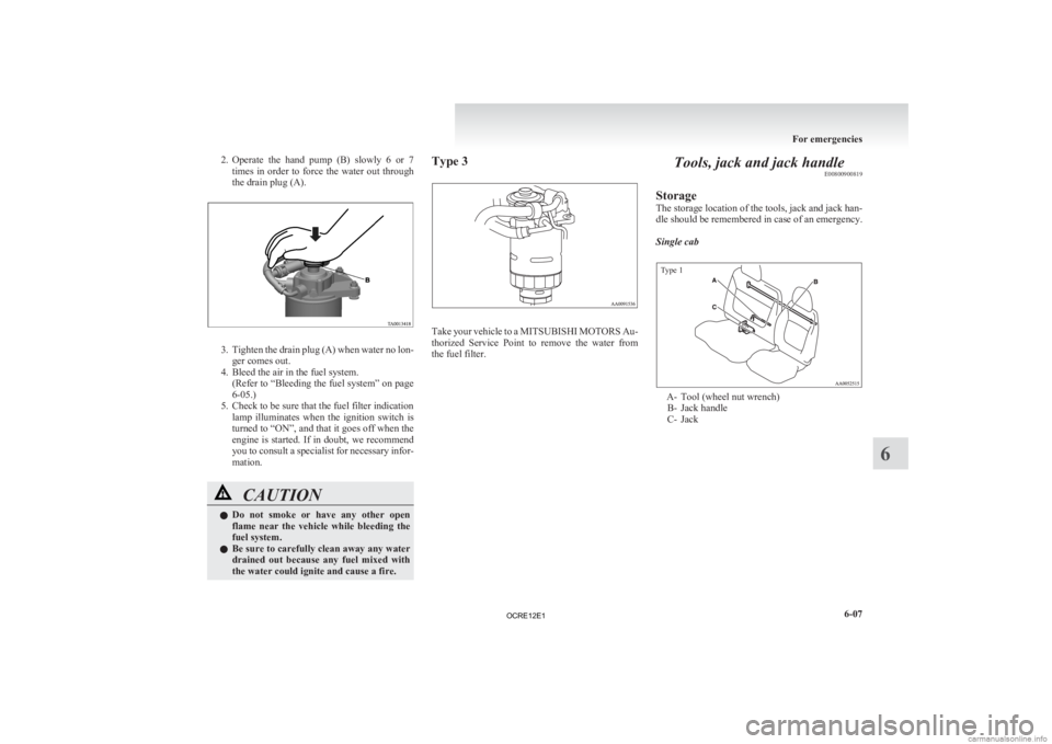
2. Operate the hand pump (B) slowly 6 or 7
times in order to force the water out through
the drain plug (A). 3. Tighten
the drain plug (A) when water no lon-
ger comes out.
4. Bleed the air in the fuel system. (Refer to “Bleeding the fuel system” on page
6-05.)
5. Check to be sure that the fuel filter indication lamp illuminates when the ignition switch is
turned to “ON”, and that it goes off when the
engine is started. If in doubt, we recommend
you to consult a specialist for necessary infor-
mation. CAUTION
l
Do
not smoke or have any other open
flame near the vehicle while bleeding the
fuel system.
l Be sure to carefully clean away any water
drained out because any fuel mixed with
the water could ignite and cause a fire. Type 3
Take your vehicle to a MITSUBISHI MOTORS
Au-
thorized Service Point to remove the water from
the fuel filter. Tools, jack and jack handle
E00800900819
Storage
The
storage location of the tools, jack and jack han-
dle should be remembered in case of an emergency.
Single cab
Type 1 A- Tool (wheel nut wrench)
B-
Jack handle
C- Jack For emergencies
6-07 6
OCRE12E1
Page 281 of 370
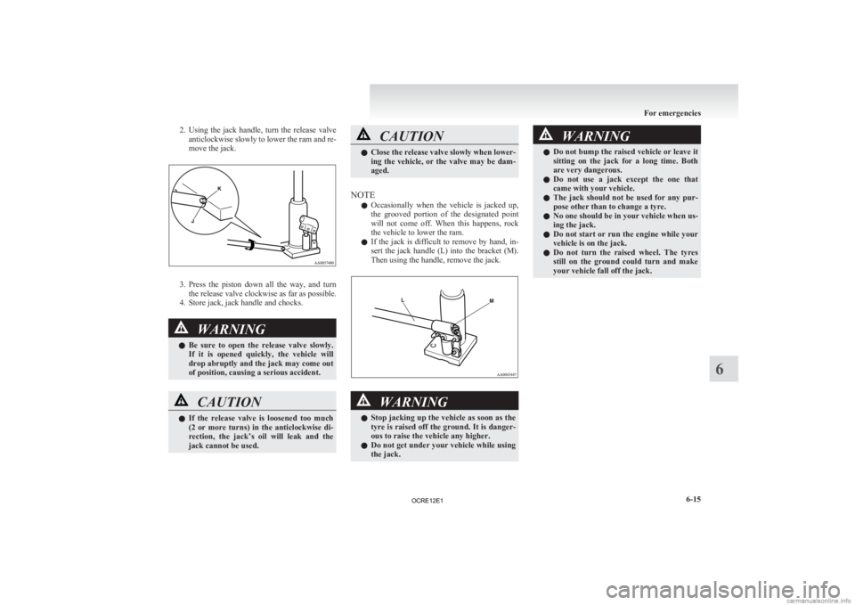
2. Using the jack handle, turn the release valve
anticlockwise slowly to lower the ram and re-
move the jack. 3. Press
the piston down all the way, and turn
the release valve clockwise as far as possible.
4. Store jack, jack handle and chocks. WARNING
l Be
sure to open the release valve slowly.
If it is opened quickly, the vehicle will
drop abruptly and the jack may come out
of position, causing a serious accident. CAUTION
l
If
the release valve is loosened too much
(2 or more turns) in the anticlockwise di-
rection, the jack’s oil will leak and the
jack cannot be used. CAUTION
l
Close
the release valve slowly when lower-
ing the vehicle, or the valve may be dam-
aged.
NOTE l Occasionally
when the vehicle is jacked up,
the grooved portion of the designated point
will not come off. When this happens, rock
the vehicle to lower the ram.
l If the jack is difficult to remove by hand, in-
sert the jack handle (L) into the bracket (M).
Then using the handle, remove the jack. WARNING
l Stop
jacking up the vehicle as soon as the
tyre is raised off the ground. It is danger-
ous to raise the vehicle any higher.
l Do not get under your vehicle while using
the jack. WARNING
l Do
not bump the raised vehicle or leave it
sitting on the jack for a long time. Both
are very dangerous.
l Do not use a jack except the one that
came with your vehicle.
l The jack should not be used for any pur-
pose other than to change a tyre.
l No one should be in your vehicle when us-
ing the jack.
l Do not start or run the engine while your
vehicle is on the jack.
l Do not turn the raised wheel. The tyres
still on the ground could turn and make
your vehicle fall off the jack. For emergencies
6-15 6
OCRE12E1
Page 286 of 370
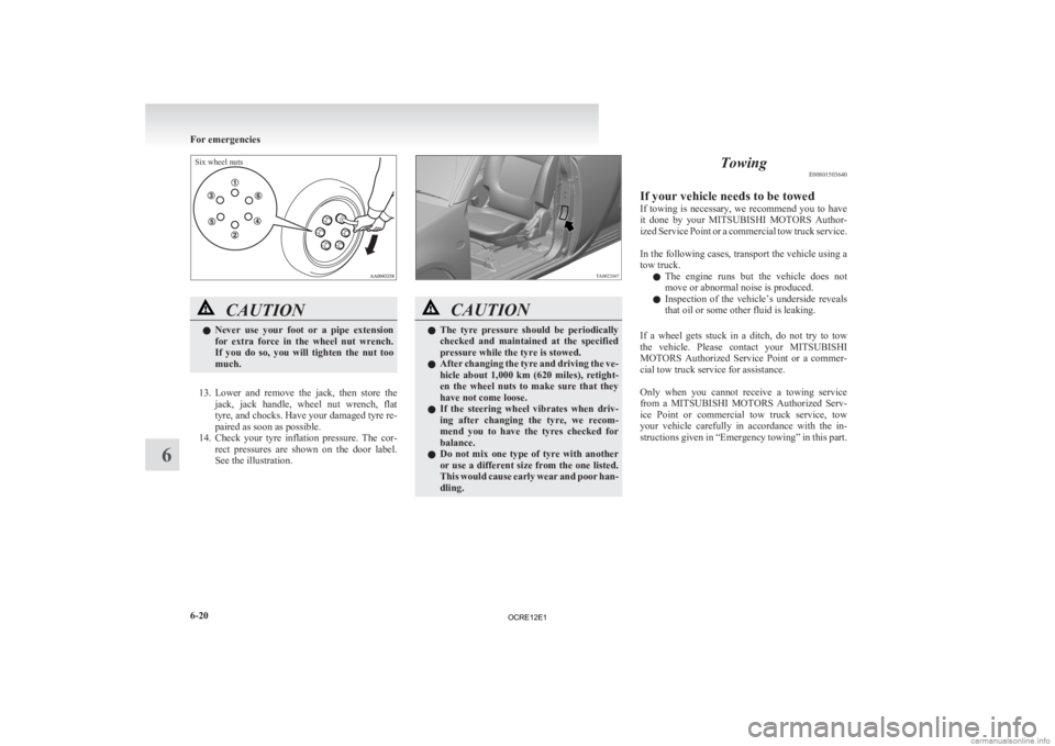
Six wheel nutsCAUTION
l
Never
use your foot or a pipe extension
for extra force in the wheel nut wrench.
If you do so, you will tighten the nut too
much.
13. Lower
and remove the jack, then store the jack, jack handle, wheel nut wrench, flat
tyre, and chocks. Have your damaged tyre re-
paired as soon as possible.
14. Check your tyre inflation pressure. The cor- rect pressures are shown on the door label.
See the illustration. CAUTION
l
The
tyre pressure should be periodically
checked and maintained at the specified
pressure while the tyre is stowed.
l After changing the tyre and driving the ve-
hicle about 1,000 km (620 miles), retight-
en the wheel nuts to make sure that they
have not come loose.
l If the steering wheel vibrates when driv-
ing after changing the tyre, we recom-
mend you to have the tyres checked for
balance.
l Do not mix one type of tyre with another
or use a different size from the one listed.
This would cause early wear and poor han-
dling. Towing
E00801503640
If your vehicle needs to be towed
If
towing is necessary, we recommend you to have
it done by your MITSUBISHI MOTORS Author-
ized Service Point or a commercial tow truck service.
In the following cases, transport the vehicle using a
tow truck.
l The engine runs but the vehicle does not
move or abnormal noise is produced.
l Inspection of the vehicle’s underside reveals
that oil or some other fluid is leaking.
If a wheel gets stuck in a ditch, do not try to tow
the vehicle. Please contact your MITSUBISHI
MOTORS Authorized Service Point or a commer-
cial tow truck service for assistance.
Only when you cannot receive a towing service
from a MITSUBISHI MOTORS Authorized Serv-
ice Point or commercial tow truck service, tow
your vehicle carefully in accordance with the in-
structions given in “Emergency towing” in this part. For emergencies
6-20
6
OCRE12E1