clock MITSUBISHI L200 2013 (in English) Owner's Guide
[x] Cancel search | Manufacturer: MITSUBISHI, Model Year: 2013, Model line: L200, Model: MITSUBISHI L200 2013Pages: 362, PDF Size: 21.07 MB
Page 198 of 362
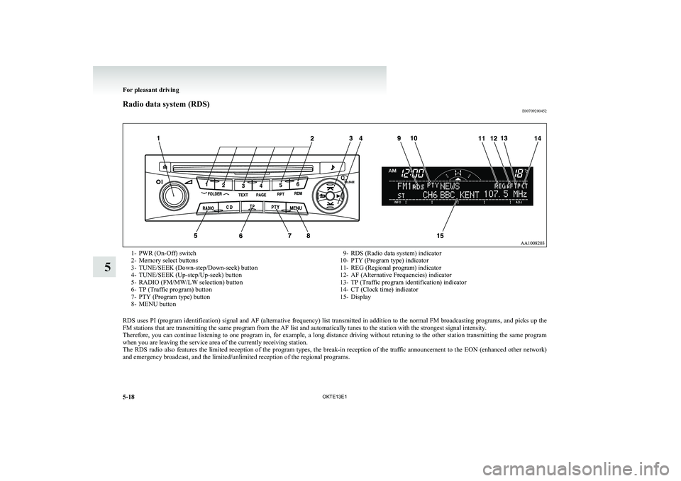
Radio data system (RDS)E007092004521- PWR (On-Off) switch
2- Memory select buttons
3- TUNE/SEEK (Down-step/Down-seek) button
4- TUNE/SEEK (Up-step/Up-seek) button
5- RADIO (FM/MW/LW selection) button
6- TP (Traffic program) button
7- PTY (Program type) button
8- MENU button9- RDS (Radio data system) indicator
10- PTY (Program type) indicator
11- REG (Regional program) indicator
12- AF (Alternative Frequencies) indicator
13- TP (Traffic program identification) indicator
14- CT (Clock time) indicator
15- Display
RDS uses PI (program identification) signal and AF (alternative frequency) list transmitted in addition to the normal FM broadcasting programs, and picks up the
FM stations that are transmitting the same program from the AF list and automatically tunes to the station with the strongest signal intensity.
Therefore, you can continue listening to one program in, for example, a long distance driving without retuning to the other station transmitting the same program
when you are leaving the service area of the currently receiving station.
The RDS radio also features the limited reception of the program types, the break-in reception of the traffic announcement to the EON (enhanced other network)
and emergency broadcast, and the limited/unlimited reception of the regional programs.
For pleasant driving
5-18 OKTE13E1
5
Page 199 of 362
AF (Alternative Frequencies) functionE00720900061
The AF function finds a station broadcasting the
same program and selects the station with the stron-
gest signal of AF lists.
The AF function is turned on (with the AF indica-
tor (12) shown on the display) at all times unless
you manually switch it off.
The AF function can be turned ON and OFF.
Refer to “Function setup mode” on page 5-21.CT (Clock Time) function E00721000131
The clock can be set automatically by using the sig-
nal from the local RDS stations. Refer to “Adjust-
ing the time” on page 3-12.
REG (Regional) function E00721100057
REG function limits to receive the stations broad-
casting regional programs.
Regional programming and regional networks are
organized differently depending on the country or
area (they may be changed according to the hour,
state, or broadcast area), so if you don’t want to re-
ceive the regional programs automatically, you can
set up REG ON not to receive regional programs.
The REG function can be turned ON and OFF.
Refer to “Function setup mode” on page 5-21.
PI (Program Identification) search function E00721200221
When travelling long distance and the recalled pre-
set station is weak, the radio searches another fre-
quency broadcasting the same programming with
the same PI code in AF list.
If there are no frequencies broadcasting the same
programming, the radio searches a frequency broad-
casting the regional programming. The radio suc-
ceeds in searching the regional programming, then
the display shows the REG indicator (11).
If the radio does not succeed in searching the re-
gional programming, the radio returns to the recal-
led preset station.
The PI function can be turned ON and OFF.
Refer to “Function setup mode” on page 5-21.
NOTE l While searching, the audio system is muted.
The display shows “WAIT” or “SEARCH”.PTY (Program type) E00721300349
RDS broadcasts are classified according to pro-
gram type (PTY) as follows. Use the TUNE/SEEK
button (3 or 4) to select your desired PTY.
1. NEWS
2. AFFAIRS (Current affairs)
3. INFO (Information)
4. SPORT
5. EDUCATE (Education)
6. DRAMA
7. CULTURE
8. SCIENCE
9. VARIED
10. POP M (Pop music)
11. ROCK M (Rock music)
12. EASY M (Easy music)
13. LIGHT M (Light classics)
14. CLASSICS
15. OTHER M (Other music)
16. WEATHER (Weather information)
17. FINANCE
18. CHILDREN
19. SOCIAL
20. RELIGION
21. PHONE IN
22. TRAVEL
23. LEISURE
24. JAZZ
25. COUNTRY
26. NATION M (National music)
27. OLDIES
28. FOLK M (Folk music)
29. DOCUMENT
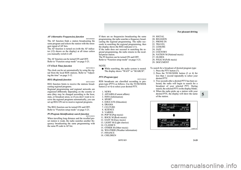
To search for a broadcast of desired program type: 1. Press the PTY button (7).
2. Press the TUNE/SEEK button (3 or 4) for
less than 1 second repeatedly to select your
desired PTY.
3. Two seconds after a desired PTY has been se-
lected, the radio will begin to search for a
broadcast of your selected PTY. During
search, the selected PTY on the display blinks.
4. When the radio picks up a station with your
desired PTY, the display will show the name
of the station.
For pleasant driving
5-19
OKTE13E1
5
Page 230 of 362
lThe unit may not successfully play back a
CD-R/RW that was made by the combina-
tion of writing software, a CD recorder
(CD-R/RW drive) and a disc if they are in-
compatible with one another.
l This player cannot play the
CD-R/RW discs
if the session is not closed.
l This player cannot play
CD-R/RW discs
which contain other than CD-DA or MP3 da-
ta (Video CD, etc.).
l Be sure to observe the handling instructions
for the CD-R/RW disc.WARNINGl Operating the CD player in a manner oth-
er than specifically instructed herein may
result in hazardous radiation exposure.
Do not remove the cover and attempt to
repair the CD player by yourself. There
are no user serviceable parts inside. In
case of malfunction, we recommend you
to have it checked.Antenna E00710500022Pillar antenna* E00710700109
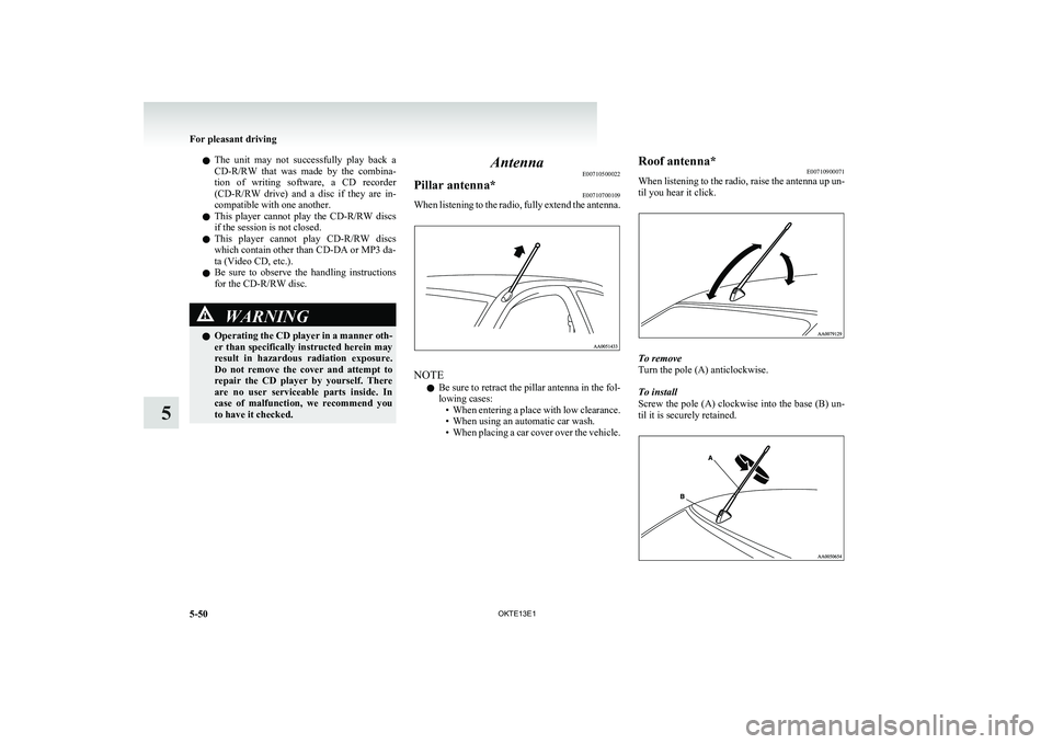
When listening to the radio, fully extend the antenna.
NOTE
l Be sure to retract the pillar antenna in the fol-
lowing cases: •When entering a place with low clearance.
• When using an automatic car wash.
• When placing a car cover over the vehicle.
Roof antenna*
E00710900071
When listening to the radio, raise the antenna up un-
til you hear it click.
To remove
Turn the pole (A) anticlockwise.
To install
Screw the pole (A) clockwise into the base (B) un-
til it is securely retained.
For pleasant driving
5-50 OKTE13E1
5
Page 253 of 362
Digital clock*E00711700193
The digital clock indicates the time with the igni-
tion switch in either “ON” or “ACC” position.
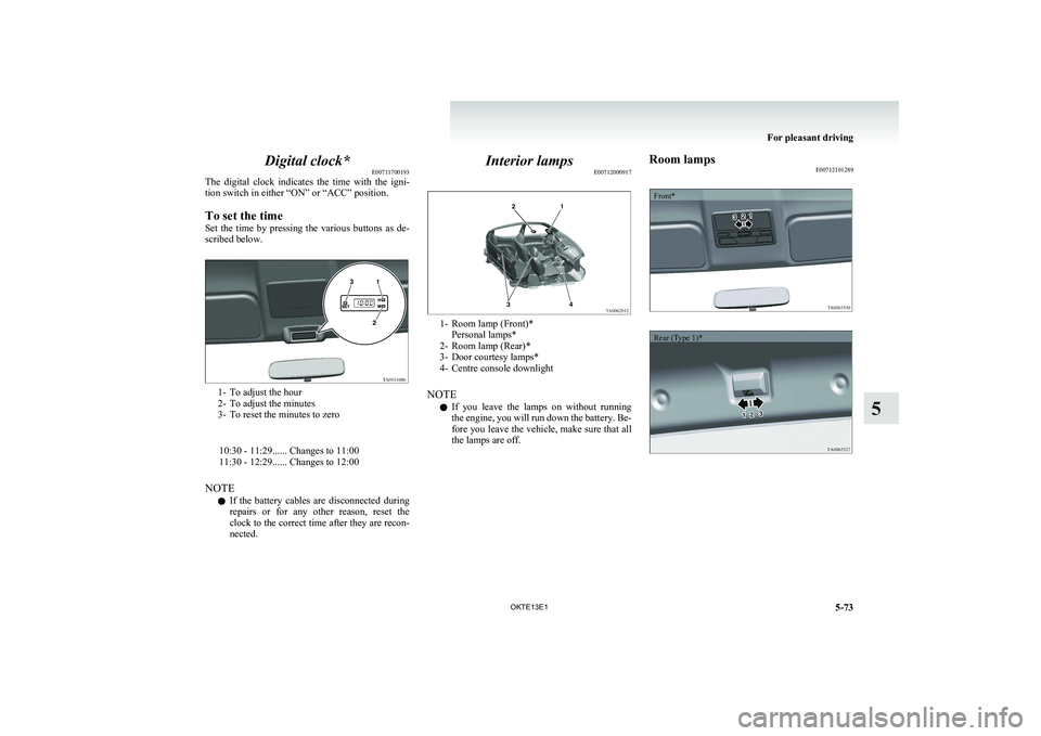
To set the time
Set the time by pressing the various buttons as de-
scribed below.
1- To adjust the hour
2- To adjust the minutes
3- To reset the minutes to zero
10:30 - 11:29...... Changes to 11:00
11:30 - 12:29...... Changes to 12:00
NOTE l If the battery cables are disconnected during
repairs or for any other reason, reset the
clock to the correct time after they are recon-
nected.
Interior lamps E00712000917
1- Room lamp (Front)*
Personal lamps*
2- Room lamp (Rear)*
3- Door courtesy lamps*
4- Centre console downlight
NOTE l If you leave the lamps on without running
the engine, you will run down the battery. Be-
fore you leave the vehicle, make sure that all
the lamps are off.
Room lamps E00712101289Front*Rear (Type 1)*
For pleasant driving
5-73
OKTE13E1
5
Page 274 of 362
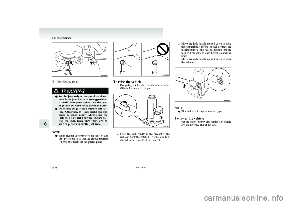
E-Rear jacking pointWARNINGlSet the jack only at the positions shown
here. If the jack is set at a wrong position,
it could dent your vehicle or the jack
might fall over and cause personal injury.
l Do not use the jack on a tilted or soft sur-
face. Otherwise, the jack might slip and
cause personal injury. Always use the
jack on a flat, hard surface. Before set-
ting the jack, make sure there are no
sand or pebbles under the jack base.
NOTE
l When jacking up the rear of the vehicle, turn
the tip of the jack so that the grooved portion
(F) properly meets the designated point.
To raise the vehicle
1.Using the jack handle, turn the release valve
(G) clockwise until it stops.
2. Insert the jack handle in the bracket of the
jack and hook the notch (H) on the jack han-
dle end to the claw (I) of the bracket.
3. Move the jack handle up and down to raise
the ram until just before the jack contacts the
jacking point of the vehicle. Ensure that the
jack will properly contact the vehicle jacking
point.
Move the jack handle up and down to raise
the vehicle.
NOTE
l This jack is a 2 stage expansion type.
To lower the vehicle 1.Put the notch (J) provided on the jack handle
end on the valve (K) of the jack.
For emergencies
6-14 OKTE13E1
6
Page 275 of 362
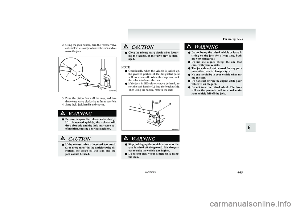
2.Using the jack handle, turn the release valve
anticlockwise slowly to lower the ram and re-
move the jack.
3. Press the piston down all the way, and turn
the release valve clockwise as far as possible.
4. Store jack, jack handle and chocks.
WARNINGl Be sure to open the release valve slowly.
If it is opened quickly, the vehicle will
drop abruptly and the jack may come out
of position, causing a serious accident.CAUTIONl If the release valve is loosened too much
(2 or more turns) in the anticlockwise di-
rection, the jack’s oil will leak and the
jack cannot be used.CAUTIONl Close the release valve slowly when lower-
ing the vehicle, or the valve may be dam-
aged.
NOTE
l Occasionally when the vehicle is jacked up,
the grooved portion of the designated point
will not come off. When this happens, rock
the vehicle to lower the ram.
l If the jack is difficult to remove by hand, in-
sert the jack handle (L) into the bracket (M).
Then using the handle, remove the jack.
WARNINGl Stop jacking up the vehicle as soon as the
tyre is raised off the ground. It is danger-
ous to raise the vehicle any higher.
l Do not get under your vehicle while using
the jack.WARNINGl Do not bump the raised vehicle or leave it
sitting on the jack for a long time. Both
are very dangerous.
l Do not use a jack except the one that
came with your vehicle.
l The jack should not be used for any pur-
pose other than to change a tyre.
l No one should be in your vehicle when us-
ing the jack.
l Do not start or run the engine while your
vehicle is on the jack.
l Do not turn the raised wheel. The tyres
still on the ground could turn and make
your vehicle fall off the jack.
For emergencies
6-15
OKTE13E1
6
Page 276 of 362
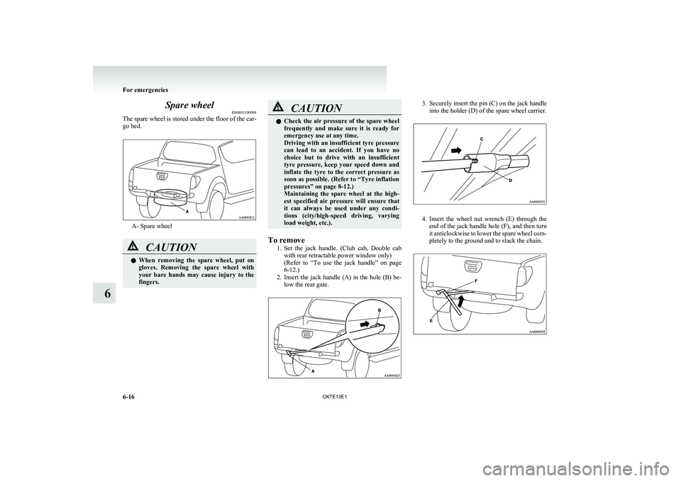
Spare wheelE00801100094
The spare wheel is stored under the floor of the car-
go bed.
A- Spare wheel
CAUTIONl When removing the spare wheel, put on
gloves. Removing the spare wheel with
your bare hands may cause injury to the
fingers.CAUTIONl Check the air pressure of the spare wheel
frequently and make sure it is ready for
emergency use at any time.
Driving with an insufficient tyre pressure
can lead to an accident. If you have no
choice but to drive with an insufficient
tyre pressure, keep your speed down and
inflate the tyre to the correct pressure as
soon as possible. (Refer to “Tyre inflation
pressures” on page 8-12.)
Maintaining the spare wheel at the high-
est specified air pressure will ensure that
it can always be used under any condi-
tions (city/high-speed driving, varying
load weight, etc.).
To remove
1.Set the jack handle. (Club cab, Double cab
with rear retractable power window only)
( Refer to “To use the jack handle” on page
6-12.)
2. Insert the jack handle (A) in the hole (B) be-
low the rear gate.
3. Securely insert the pin (C) on the jack handle
into the holder (D) of the spare wheel carrier.
4. Insert the wheel nut wrench (E) through the
end of the jack handle hole (F), and then turn
it anticlockwise to lower the spare wheel com-
pletely to the ground and to slack the chain.
For emergencies
6-16 OKTE13E1
6
Page 277 of 362
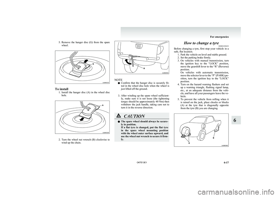
5.Remove the hanger disc (G) from the spare
wheel.
To install
1.Install the hanger disc (A) in the wheel disc
hole.
2. Turn the wheel nut wrench (B) clockwise to
wind up the chain.
NOTE
l Confirm that the hanger disc is securely fit-
ted in the wheel disc hole when the wheel is
just lifted off the ground.
3. After winding up the spare wheel sufficient-
ly, make sure it is not loose (the tightening
torque should be approximately 40 Nm) then
withdraw the jack handle, taking care not to
turn it in the reverse direction.
CAUTIONl The spare wheel should always be secure-
ly in position.
If a flat tyre is changed, put the flat tyre
in the spare wheel mounting position
with the wheel outer surface upward, and
use the wheel nut wrench to secure it firm-
ly.How to change a tyre E00801202653
Before changing a tyre, first stop your vehicle in a
safe, flat location. 1. Park the vehicle on level and stable ground.
2. Set the parking brake firmly.
3. On vehicles with manual transmission, turn
the ignition key to the “LOCK” position,
move the gearshift lever to the “R” (Reverse)
position.
On vehicles with automatic transmission,
move the selector lever to the “P” (PARK) po-
sition, turn the ignition key to the “LOCK”
position.
4. Turn on the hazard warning flashers and set
up a warning triangle, flashing signal lamp,
etc., at an adequate distance from the vehi-
cle, and have all your passengers leave the ve-
hicle.
5. To prevent the vehicle from rolling when it
is raised on the jack, place chocks or blocks
(A) at the tyre that is diagonally opposite
from the tyre (B) you are changing.
For emergencies
6-17
OKTE13E1
6
Page 279 of 362
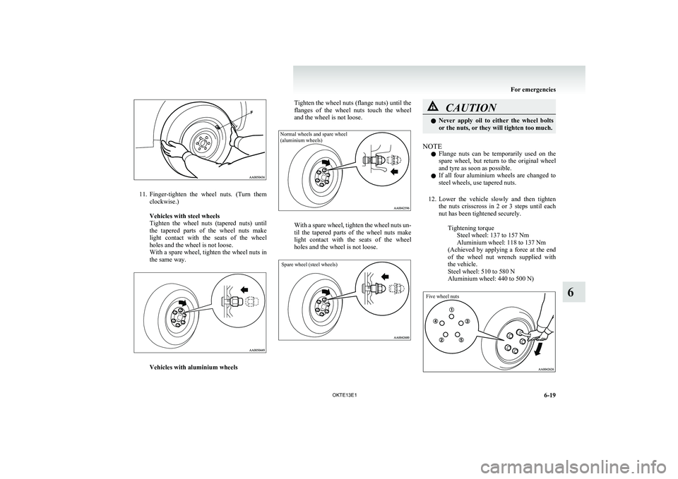
11.Finger-tighten the wheel nuts. (Turn them
clockwise.)
Vehicles with steel wheels
Tighten the wheel nuts (tapered nuts) until
the tapered parts of the wheel nuts make
light contact with the seats of the wheel
holes and the wheel is not loose.
With a spare wheel, tighten the wheel nuts in
the same way.
Vehicles with aluminium wheels
Tighten the wheel nuts (flange nuts) until the
flanges of the wheel nuts touch the wheel
and the wheel is not loose.Normal wheels and spare wheel
(aluminium wheels)
With a spare wheel, tighten the wheel nuts un-
til the tapered parts of the wheel nuts make
light contact with the seats of the wheel
holes and the wheel is not loose.
Spare wheel (steel wheels)
CAUTIONl Never apply oil to either the wheel bolts
or the nuts, or they will tighten too much.
NOTE
l Flange nuts can be temporarily used on the
spare wheel, but return to the original wheel
and tyre as soon as possible.
l If all four aluminium wheels are changed to
steel wheels, use tapered nuts.
12. Lower the vehicle slowly and then tighten
the nuts crisscross in 2 or 3 steps until each
nut has been tightened securely.
Tightening torqueSteel wheel: 137 to 157 Nm
Aluminium wheel: 118 to 137 Nm
( Achieved by applying a force at the end
of the wheel nut wrench supplied with
the vehicle.
Steel wheel: 510 to 580 N
Aluminium wheel: 440 to 500 N)
Five wheel nuts
For emergencies
6-19
OKTE13E1
6
Page 317 of 362
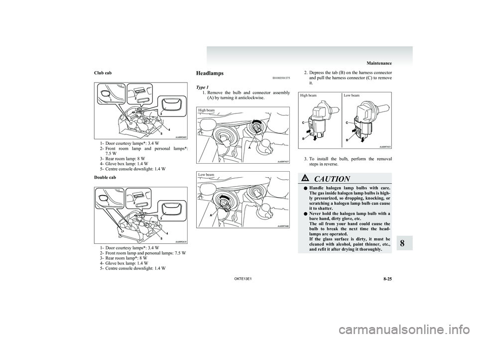
Club cab
1- Door courtesy lamps*: 3.4 W
2- Front room lamp and personal lamps*:
7.5 W
3- Rear room lamp: 8 W
4- Glove box lamp: 1.4 W
5- Centre console downlight: 1.4 W
Double cab
1- Door courtesy lamps*: 3.4 W
2- Front room lamp and personal lamps: 7.5 W
3- Rear room lamp*: 8 W
4- Glove box lamp: 1.4 W
5- Centre console downlight: 1.4 W
Headlamps E01003501375
Type 1 1.Remove the bulb and connector assembly
(A) by turning it anticlockwise.High beamLow beam2. Depress the tab (B) on the harness connector
and pull the harness connector (C) to remove
it.High beamLow beam
3. To install the bulb, perform the removal
steps in reverse.
CAUTIONl Handle halogen lamp bulbs with care.
The gas inside halogen lamp bulbs is high-
ly pressurized, so dropping, knocking, or
scratching a halogen lamp bulb can cause
it to shatter.
l Never hold the halogen lamp bulb with a
bare hand, dirty glove, etc.
The oil from your hand could cause the
bulb to break the next time the head-
lamps are operated.
If the glass surface is dirty, it must be
cleaned with alcohol, paint thinner, etc.,
and refit it after drying it thoroughly.
Maintenance
8-25
OKTE13E1
8