spare wheel MITSUBISHI L200 2013 Owner's Manual (in English)
[x] Cancel search | Manufacturer: MITSUBISHI, Model Year: 2013, Model line: L200, Model: MITSUBISHI L200 2013Pages: 362, PDF Size: 21.07 MB
Page 19 of 362
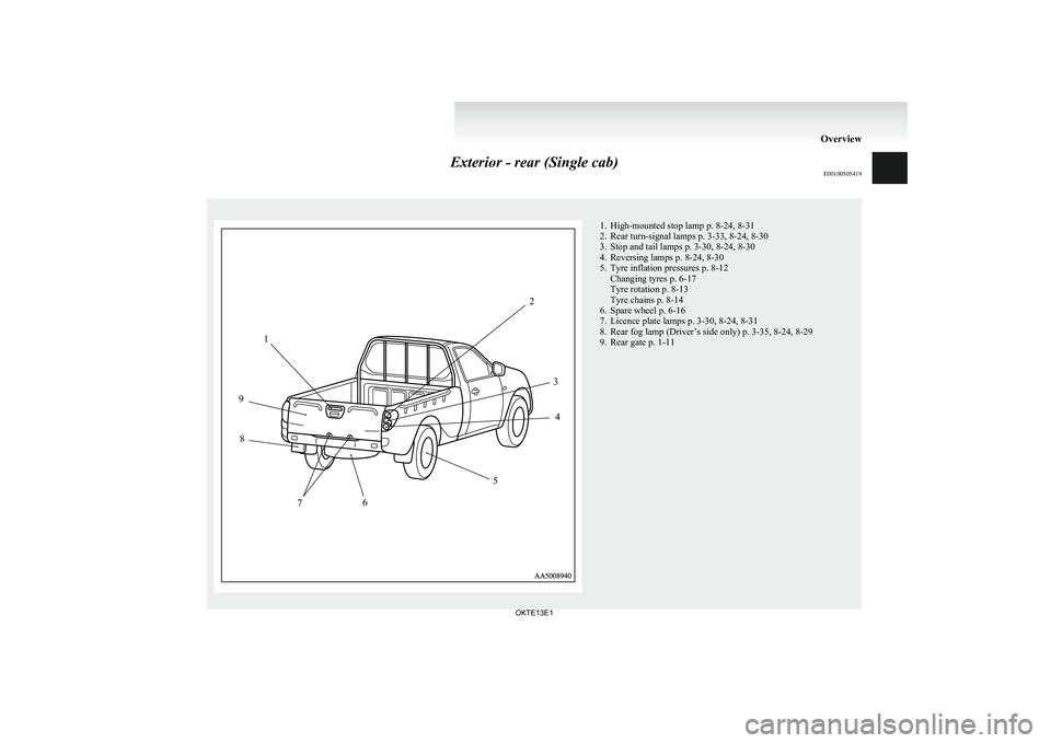
Exterior - rear (Single cab)E00100505419
1234567891. High-mounted stop lamp p. 8-24, 8-31
2. Rear turn-signal lamps p. 3-33, 8-24, 8-30
3. Stop and tail lamps p. 3-30, 8-24, 8-30
4. Reversing lamps p. 8-24, 8-30
5. Tyre inflation pressures p. 8-12 Changing tyres p. 6-17
Tyre rotation p. 8-13
Tyre chains p. 8-14
6. Spare wheel p. 6-16
7. Licence plate lamps p. 3-30, 8-24, 8-31
8. Rear fog lamp (Driver’s side only) p. 3-35, 8-24, 8-29
9. Rear gate p. 1-11
Overview
OKTE13E1
Page 21 of 362
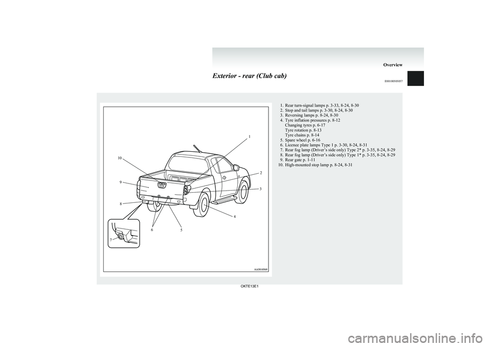
Exterior - rear (Club cab)E001005050571. Rear turn-signal lamps p. 3-33, 8-24, 8-30
2. Stop and tail lamps p. 3-30, 8-24, 8-30
3. Reversing lamps p. 8-24, 8-30
4. Tyre inflation pressures p. 8-12 Changing tyres p. 6-17
Tyre rotation p. 8-13
Tyre chains p. 8-14
5. Spare wheel p. 6-16
6. Licence plate lamps Type 1 p. 3-30, 8-24, 8-31
7. Rear fog lamp (Driver’s side only) Type 2* p. 3-35, 8-24, 8-29
8. Rear fog lamp (Driver’s side only) Type 1* p. 3-35, 8-24, 8-29
9. Rear gate p. 1-11
10. High-mounted stop lamp p. 8-24, 8-31
Overview
OKTE13E112
3
4
5
6
7 8
9
10
Page 23 of 362
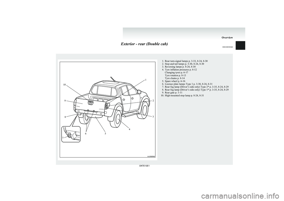
Exterior - rear (Double cab)E001005050601. Rear turn-signal lamps p. 3-33, 8-24, 8-30
2. Stop and tail lamps p. 3-30, 8-24, 8-30
3. Reversing lamps p. 8-24, 8-30
4. Tyre inflation pressures p. 8-12 Changing tyres p. 6-17
Tyre rotation p. 8-13
Tyre chains p. 8-14
5. Spare wheel p. 6-16
6. Licence plate lamps Type 1 p. 3-30, 8-24, 8-31
7. Rear fog lamp (Driver’s side only) Type 2* p. 3-35, 8-24, 8-29
8. Rear fog lamp (Driver’s side only) Type 1* p. 3-35, 8-24, 8-29
9. Rear gate p. 1-11
10. High-mounted stop lamp p. 8-24, 8-31
Overview
OKTE13E112
3
4
5
6
7 8
9
10
Page 261 of 362
If the vehicle breaks down............................................................ 6-02
Emergency starting ....................................................................... 6-02
Engine overheating ....................................................................... 6-04
Bleeding the fuel system...............................................................6-05
Removal of water from the fuel filter ...........................................6-06
Tools, jack and jack handle .......................................................... 6-07
Jacking up the vehicle...................................................................6-13
Spare wheel...................................................................................6-16
How to change a tyre .................................................................... 6-17
Towing .......................................................................................... 6-20
Operation under adverse driving conditions .................................6-24For emergencies
OKTE13E1
6
Page 273 of 362
Jacking up the vehicleE00801001436
1. Park the vehicle on level and stable ground.
2. Set the parking brake firmly.
3. On vehicles with manual transmission, turn
the ignition key to the “LOCK” position,
move the gearshift lever to the “R” (Reverse)
position.
On vehicles with automatic transmission,
move the selector lever to the “P” (PARK) po-
sition, turn the ignition key to the “LOCK”
position.
4. Turn on the hazard warning flashers and set
up a warning triangle, flashing signal lamp,
etc., at an adequate distance from the vehi-
cle, and have all your passengers leave the ve-
hicle.
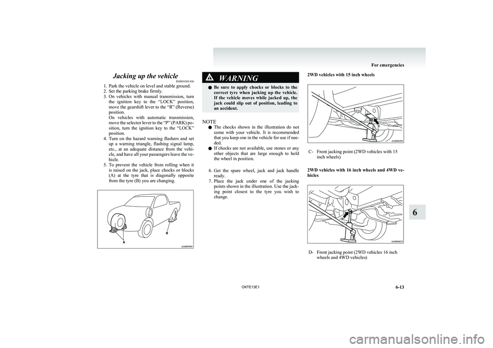
5. To prevent the vehicle from rolling when it
is raised on the jack, place chocks or blocks
(A) at the tyre that is diagonally opposite
from the tyre (B) you are changing.WARNINGl Be sure to apply chocks or blocks to the
correct tyre when jacking up the vehicle.
If the vehicle moves while jacked up, the
jack could slip out of position, leading to
an accident.
NOTE
l The chocks shown in the illustration do not
come with your vehicle. It is recommended
that you keep one in the vehicle for use if nee-
ded.
l If chocks are not available, use stones or any
other objects that are large enough to hold
the wheel in position.
6. Get the spare wheel, jack and jack handle
ready.
7. Place the jack under one of the jacking
points shown in the illustration. Use the jack-
ing point closest to the tyre you wish to
change.
2WD vehicles with 15 inch wheelsC-Front jacking point (2WD vehicles with 15
inch wheels)
2WD vehicles with 16 inch wheels and 4WD ve-
hicles
D-Front jacking point (2WD vehicles 16 inch
wheels and 4WD vehicles)
For emergencies
6-13
OKTE13E1
6
Page 276 of 362
Spare wheelE00801100094
The spare wheel is stored under the floor of the car-
go bed.
A- Spare wheel
CAUTIONl When removing the spare wheel, put on
gloves. Removing the spare wheel with
your bare hands may cause injury to the
fingers.CAUTIONl Check the air pressure of the spare wheel
frequently and make sure it is ready for
emergency use at any time.
Driving with an insufficient tyre pressure
can lead to an accident. If you have no
choice but to drive with an insufficient
tyre pressure, keep your speed down and
inflate the tyre to the correct pressure as
soon as possible. (Refer to “Tyre inflation
pressures” on page 8-12.)
Maintaining the spare wheel at the high-
est specified air pressure will ensure that
it can always be used under any condi-
tions (city/high-speed driving, varying
load weight, etc.).
To remove
1.Set the jack handle. (Club cab, Double cab
with rear retractable power window only)
( Refer to “To use the jack handle” on page
6-12.)
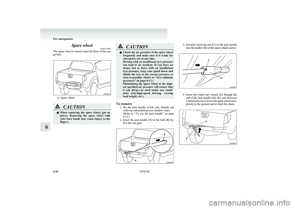
2. Insert the jack handle (A) in the hole (B) be-
low the rear gate.
3. Securely insert the pin (C) on the jack handle
into the holder (D) of the spare wheel carrier.
4. Insert the wheel nut wrench (E) through the
end of the jack handle hole (F), and then turn
it anticlockwise to lower the spare wheel com-
pletely to the ground and to slack the chain.
For emergencies
6-16 OKTE13E1
6
Page 277 of 362
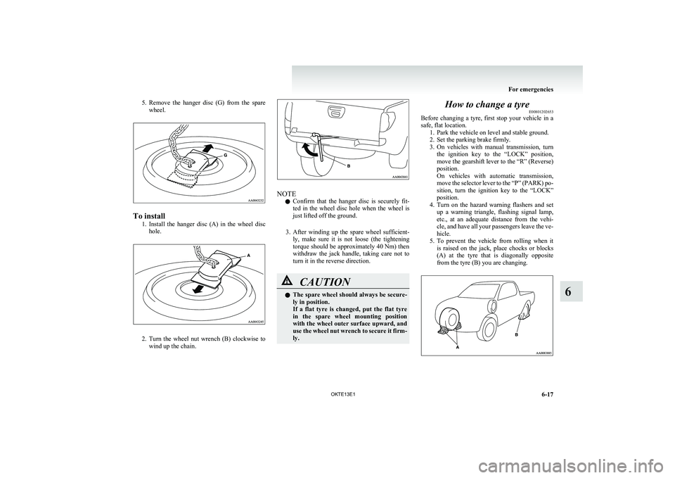
5.Remove the hanger disc (G) from the spare
wheel.
To install
1.Install the hanger disc (A) in the wheel disc
hole.
2. Turn the wheel nut wrench (B) clockwise to
wind up the chain.
NOTE
l Confirm that the hanger disc is securely fit-
ted in the wheel disc hole when the wheel is
just lifted off the ground.
3. After winding up the spare wheel sufficient-
ly, make sure it is not loose (the tightening
torque should be approximately 40 Nm) then
withdraw the jack handle, taking care not to
turn it in the reverse direction.
CAUTIONl The spare wheel should always be secure-
ly in position.
If a flat tyre is changed, put the flat tyre
in the spare wheel mounting position
with the wheel outer surface upward, and
use the wheel nut wrench to secure it firm-
ly.How to change a tyre E00801202653
Before changing a tyre, first stop your vehicle in a
safe, flat location. 1. Park the vehicle on level and stable ground.
2. Set the parking brake firmly.
3. On vehicles with manual transmission, turn
the ignition key to the “LOCK” position,
move the gearshift lever to the “R” (Reverse)
position.
On vehicles with automatic transmission,
move the selector lever to the “P” (PARK) po-
sition, turn the ignition key to the “LOCK”
position.
4. Turn on the hazard warning flashers and set
up a warning triangle, flashing signal lamp,
etc., at an adequate distance from the vehi-
cle, and have all your passengers leave the ve-
hicle.
5. To prevent the vehicle from rolling when it
is raised on the jack, place chocks or blocks
(A) at the tyre that is diagonally opposite
from the tyre (B) you are changing.
For emergencies
6-17
OKTE13E1
6
Page 278 of 362
WARNINGlBe sure to apply chocks or blocks to the
correct tyre when jacking up the vehicle.
If the vehicle moves while jacked up, the
jack could slip out of position, leading to
an accident.
NOTE
l The chocks shown in the illustration do not
come with your vehicle. It is recommended
that you keep one in the vehicle for use if nee-
ded.
l If chocks are not available, use stones or any
other objects that are large enough to hold
the wheel in position.
6. Get the spare wheel, jack, jack handle and
wheel nut wrench ready.
NOTE
l Put the spare wheel under the vehicle body
near the flat tyre. This makes it safer if the
jack slips out of position.
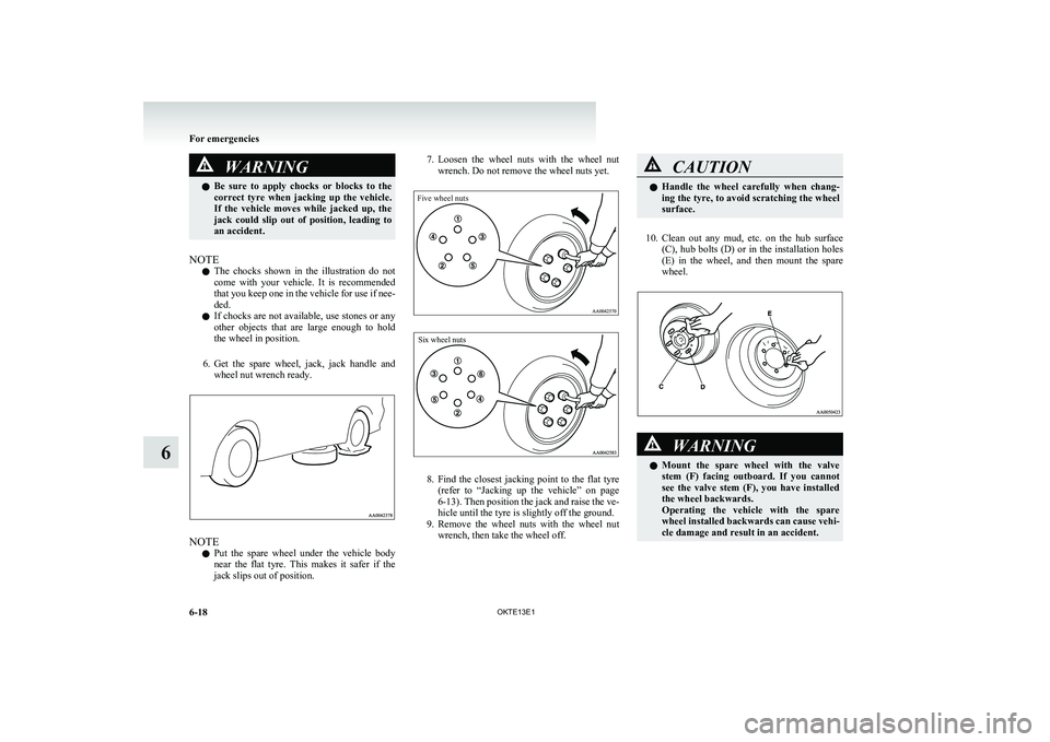
7. Loosen the wheel nuts with the wheel nut
wrench. Do not remove the wheel nuts yet.Five wheel nutsSix wheel nuts
8. Find the closest jacking point to the flat tyre
(refer to “Jacking up the vehicle” on page
6-13 ). Then position the jack and raise the ve-
hicle until the tyre is slightly off the ground.
9. Remove the wheel nuts with the wheel nut
wrench, then take the wheel off.
CAUTIONl Handle the wheel carefully when chang-
ing the tyre, to avoid scratching the wheel
surface.
10. Clean out any mud, etc. on the hub surface
(C), hub bolts (D) or in the installation holes
(E) in the wheel, and then mount the spare
wheel.
WARNINGl Mount the spare wheel with the valve
stem (F) facing outboard. If you cannot
see the valve stem (F), you have installed
the wheel backwards.
Operating the vehicle with the spare
wheel installed backwards can cause vehi-
cle damage and result in an accident.
For emergencies
6-18 OKTE13E1
6
Page 279 of 362
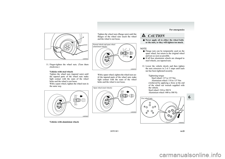
11.Finger-tighten the wheel nuts. (Turn them
clockwise.)
Vehicles with steel wheels
Tighten the wheel nuts (tapered nuts) until
the tapered parts of the wheel nuts make
light contact with the seats of the wheel
holes and the wheel is not loose.
With a spare wheel, tighten the wheel nuts in
the same way.
Vehicles with aluminium wheels
Tighten the wheel nuts (flange nuts) until the
flanges of the wheel nuts touch the wheel
and the wheel is not loose.Normal wheels and spare wheel
(aluminium wheels)
With a spare wheel, tighten the wheel nuts un-
til the tapered parts of the wheel nuts make
light contact with the seats of the wheel
holes and the wheel is not loose.
Spare wheel (steel wheels)
CAUTIONl Never apply oil to either the wheel bolts
or the nuts, or they will tighten too much.
NOTE
l Flange nuts can be temporarily used on the
spare wheel, but return to the original wheel
and tyre as soon as possible.
l If all four aluminium wheels are changed to
steel wheels, use tapered nuts.
12. Lower the vehicle slowly and then tighten
the nuts crisscross in 2 or 3 steps until each
nut has been tightened securely.
Tightening torqueSteel wheel: 137 to 157 Nm
Aluminium wheel: 118 to 137 Nm
( Achieved by applying a force at the end
of the wheel nut wrench supplied with
the vehicle.
Steel wheel: 510 to 580 N
Aluminium wheel: 440 to 500 N)
Five wheel nuts
For emergencies
6-19
OKTE13E1
6
Page 291 of 362
CAUTIONlDo not use a scrubbing brush or other
hard tools as they may damage the plastic
part surface.
l Do not use wax containing compound (pol-
ishing powder) which may damage the
plastic part surface.
l Do not bring the plastic parts into contact
with petrol, light oil, brake fluids, engine
oils, greases, paint thinners, and sulphu-
ric acid (battery electrolyte) which may
crack, stain or discolour the plastic parts.
If they touch the plastic parts, wipe them
off with soft cloth, chamois or the like
and an aqueous solution of neutral deter-
gent then immediately rinse the affected
parts with water.Chrome parts E00901400014
In order to prevent spots and corrosion of chrome
parts, wash with water, dry thoroughly, and apply a
special protective coating. This should be done
more frequently in winter.
Aluminium wheels* E00901500116
1.Remove dirt using a sponge while sprinkling
water on the vehicle.
2. Use neutral detergent on any dirt that cannot
be removed easily with water.
Rinse off the neutral detergent after washing
the vehicle.
3. Dry the vehicle thoroughly using a chamois
leather or a soft cloth.
CAUTIONl Do not use a brush or other hard imple-
ment on the wheels.
Doing so could scratch the wheels.
l Do not use any cleaner that contains an
abrasive substance or is acidic or alka-
line. Doing so could cause the coating on
the wheels to peel or become discoloured
or stained.
l Do not directly apply hot water using a
steam cleaner or by any other means.
l Contact with seawater and road deicer
can cause corrosion. Rinse off such sub-
stances as soon as possible.Window glass E00901600058
The window glass can normally be cleaned using
only a sponge and water.
Glass cleaner can be used to remove oil, grease,
dead insects, etc. After washing the glass, wipe dry
with a clean, dry, soft cloth. Never use the same
cloth to wipe the window glass as would be used to
wipe the paintwork; wax from the painted surfaces
could adhere to the glass and reduce its transparen-
cy and visibility.
NOTE l To clean the inside of the rear window, al-
ways use a soft cloth and wipe the window
glass along the demister heater element so as
not to cause damage.
Wiper blades E00901700017
Use a soft cloth and glass cleaner to remove grease,
dead insects, etc., from the wiper blades. Replace
the wiper blades when they no longer wipe proper-
ly. (Refer to page “Wiper blades” on page 8-17.)Cleaning the sunroof* E00901800180
Clean the inside of the sunroof with a soft cloth.
Hard deposits should be wiped away with a cloth
dipped in warm, neutral detergent solution. Wipe
away the solution with a sponge dipped in fresh wa-
ter.
NOTE l The surface treatment on the inside of the
glass may be removed if hard cloth or organ-
ic solvent (benzine, kerosene, thinner, etc.) is
used.
Engine compartment E00902100265
Clean the engine compartment at the beginning and
end of winter. Pay particular attention to flanges,
crevices and peripheral parts where dust containing
road chemicals and other corrosive materials might
collect.
If salt and other chemicals are used on the roads in
your area, clean the engine compartment at least ev-
ery three months.
Never spray or splash water on the electrical com-
ponents in the engine compartment, as this may
cause damage.
Do not bring the nearby parts, the plastic parts and
so on into contact with sulphuric acid (battery elec-
trolyte) which may crack, stain or discolour them.
Vehicle care
7-05
OKTE13E1
7