rear view mirror MITSUBISHI L200 2014 (in English) User Guide
[x] Cancel search | Manufacturer: MITSUBISHI, Model Year: 2014, Model line: L200, Model: MITSUBISHI L200 2014Pages: 362, PDF Size: 20.97 MB
Page 22 of 362
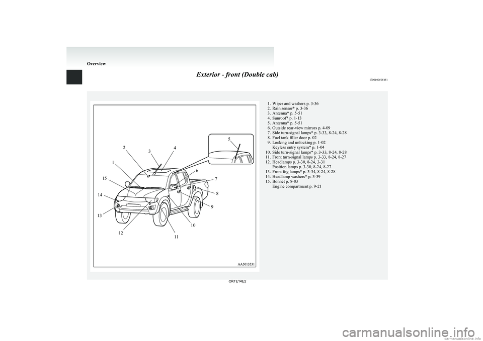
Exterior - front (Double cab)E00100505451
2345678910111213141511. Wiper and washers p. 3-36
2. Rain sensor* p. 3-36
3. Antenna* p. 5-51
4. Sunroof* p. 1-13
5. Antenna* p. 5-51
6. Outside rear-view mirrors p. 4-09
7. Side turn-signal lamps* p. 3-33, 8-24, 8-28
8. Fuel tank filler door p. 02
9. Locking and unlocking p. 1-02 Keyless entry system* p. 1-04
10. Side turn-signal lamps* p. 3-33, 8-24, 8-28
11. Front turn-signal lamps p. 3-33, 8-24, 8-27
12. Headlamps p. 3-30, 8-24, 3-31 Position lamps p. 3-30, 8-24, 8-27
13. Front fog lamps* p. 3-34, 8-24, 8-28
14. Headlamp washers* p. 3-39
15. Bonnet p. 8-03 Engine compartment p. 9-21
Overview
OKTE14E2
Page 125 of 362
Economical driving.......................................................................4-02
Driving, alcohol and drugs ........................................................... 4-02
Safe driving techniques ................................................................ 4-03
Running-in recommendations.......................................................4-04
Parking brake ................................................................................ 4-06
Parking .......................................................................................... 4-07
Steering wheel height adjustment .................................................4-08
Inside rear-view mirror ................................................................. 4-08
Outside rear-view mirrors ............................................................. 4-09
Ignition switch .............................................................................. 4-10
Steering wheel lock ...................................................................... 4-12
Starting..........................................................................................4-12
Diesel particulate filter (DPF)* .................................................... 4-13
Manual transmission ..................................................................... 4-14
Automatic transmission Sports Mode 4A/T, 5A/T .......................4-17
Easy select 4WD* ......................................................................... 4-22
Super select 4WD* ....................................................................... 4-26
Rear differential lock* .................................................................. 4-30
4-wheel drive operation ................................................................ 4-34
Inspection and maintenance following rough road oper- ation .......................................................................................... 4-36
Cautions on handling of 4-wheel drive vehicles ..........................4-36
Limited-slip differential* .............................................................. 4-38
Braking ......................................................................................... 4-38
Brake assist system* ..................................................................... 4-39
Anti-lock brake system (ABS)* ................................................... 4-39
Power steering system .................................................................. 4-42
Active Stability & Traction Control (ASTC)* .............................4-42
Cruise control* ............................................................................. 4-45
Cargo loads ................................................................................... 4-49Trailer towing
............................................................................... 4-49Starting and driving
OKTE14E2
4
Page 132 of 362
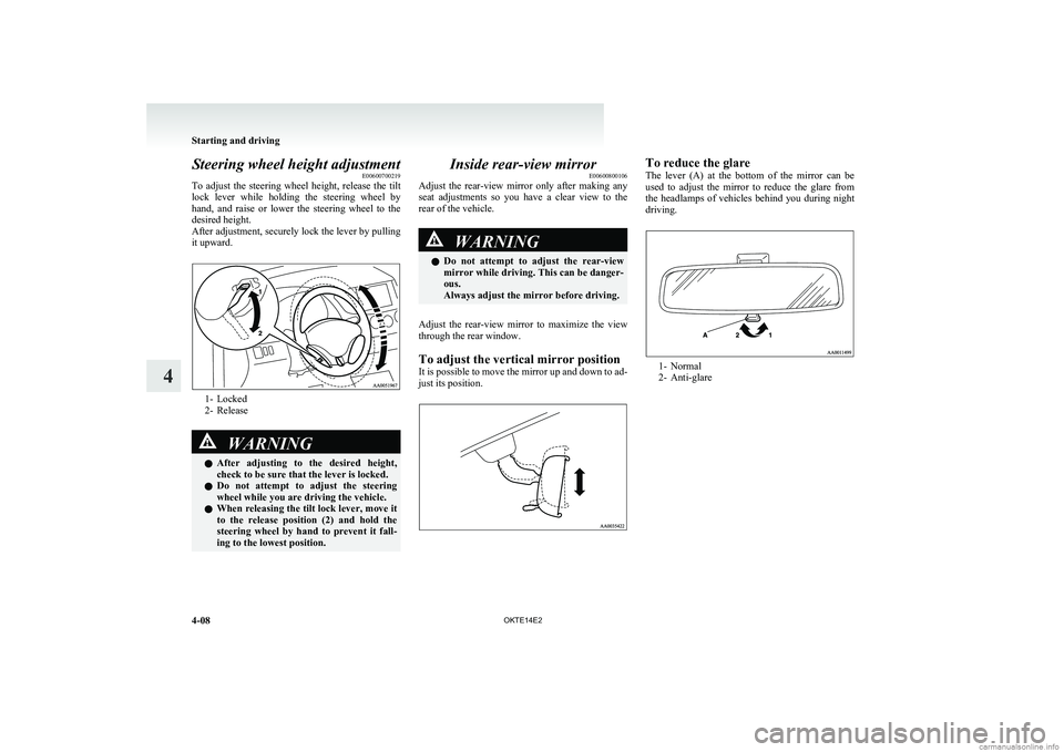
Steering wheel height adjustmentE00600700219
To adjust the steering wheel height, release the tilt
lock lever while holding the steering wheel by
hand, and raise or lower the steering wheel to the
desired height.
After adjustment, securely lock the lever by pulling
it upward.
1- Locked
2- Release
WARNINGl After adjusting to the desired height,
check to be sure that the lever is locked.
l Do not attempt to adjust the steering
wheel while you are driving the vehicle.
l When releasing the tilt lock lever, move it
to the release position (2) and hold the
steering wheel by hand to prevent it fall-
ing to the lowest position.Inside rear-view mirror E00600800106
Adjust the rear-view mirror only after making any
seat adjustments so you have a clear view to the
rear of the vehicle.WARNINGl Do not attempt to adjust the rear-view
mirror while driving. This can be danger-
ous.
Always adjust the mirror before driving.
Adjust the rear-view mirror to maximize the view
through the rear window.
To adjust the vertical mirror position
It is possible to move the mirror up and down to ad-
just its position.
To reduce the glare
The lever (A) at the bottom of the mirror can be
used to adjust the mirror to reduce the glare from
the headlamps of vehicles behind you during night
driving.
1- Normal
2- Anti-glare
Starting and driving
4-08 OKTE14E2
4
Page 133 of 362
Outside rear-view mirrorsE00600900149To adjust the mirror position E00601000482WARNINGlDo not attempt to adjust the rear-view
mirrors while driving. This can be danger-
ous.
Always adjust the mirrors before driving.
l Your vehicle is equipped with convex
type mirrors.
Please take into consideration, that ob-
jects you see in the mirror will look small-
er and farther away compared to a nor-
mal flat mirror.
Do not use this mirror to estimate dis-
tance of following vehicles when changing
lanes.
Manual outside rear-view mirrors*
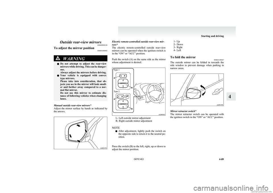
Adjust the mirror surface by hands as indicated by
the arrows.
Electric remote-controlled outside rear-view mir-
rors*
The electric remote-controlled outside rear-view
mirrors can be operated when the ignition switch is
in the “ON” or “ACC” position.
Push the switch (A) on the same side as the mirror
whose adjustment is desired.Type 1Type 2
L- Left outside mirror adjustment
R- Right outside mirror adjustment
NOTE l After adjustment, lightly push the switch on
the opposite side to return it to the neutral po-
sition.
Press the switch (B) to the left, right, up or down to
adjust the mirror position.
1- Up
2- Down
3- Right
4- LeftTo fold the mirror E00601100467
The outside mirror can be folded in towards the
side window to prevent damage when parking in
narrow areas.
Mirror retractor switch*
The mirror retractor switch can be operated with
the ignition switch in the “ON” or “ACC” position.
Starting and driving
4-09
OKTE14E2
4
Page 134 of 362
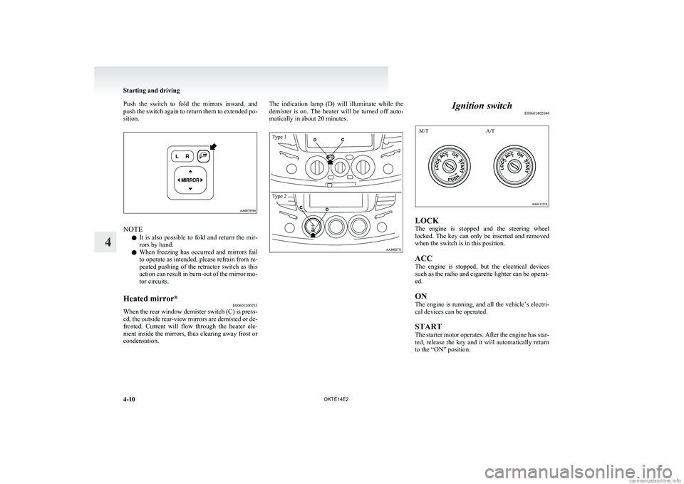
Push the switch to fold the mirrors inward, and
push the switch again to return them to extended po-
sition.
NOTE
l It is also possible to fold and return the mir-
rors by hand.
l When freezing has occurred and mirrors fail
to operate as intended, please refrain from re-
peated pushing of the retractor switch as this
action can result in burn-out of the mirror mo-
tor circuits.
Heated mirror* E00601200253
When the rear window demister switch (C) is press-
ed, the outside rear-view mirrors are demisted or de-
frosted. Current will flow through the heater ele-
ment inside the mirrors, thus clearing away frost or
condensation.
The indication lamp (D) will illuminate while the
demister is on. The heater will be turned off auto-
matically in about 20 minutes.Type 1Type 2
Ignition switch E00601402044
M/TA/T
LOCK
The engine is stopped and the steering wheel
locked. The key can only be inserted and removed
when the switch is in this position.
ACC
The engine is stopped, but the electrical devices
such as the radio and cigarette lighter can be operat-
ed.
ON
The engine is running, and all the vehicle’s electri-
cal devices can be operated.
START
The starter motor operates. After the engine has star-
ted, release the key and it will automatically return
to the “ON” position.
Starting and driving
4-10 OKTE14E2
4
Page 311 of 362
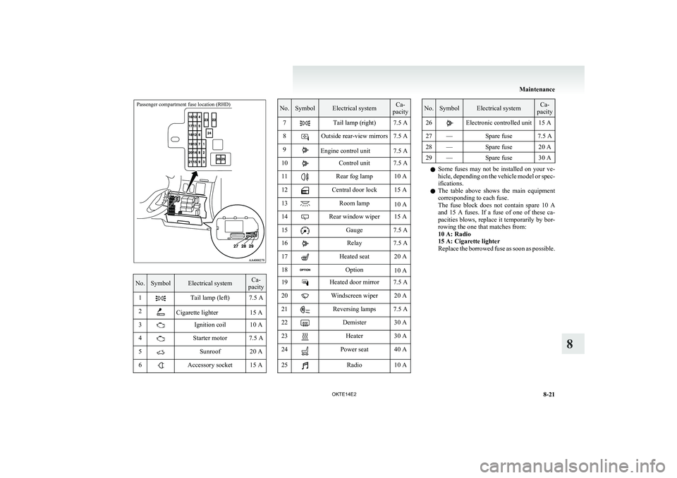
Passenger compartment fuse location (RHD)
No.SymbolElectrical systemCa-
pacity1Tail lamp (left)7.5 A2Cigarette lighter15 A3Ignition coil10 A4Starter motor7.5 A5Sunroof20 A6Accessory socket15 ANo.SymbolElectrical systemCa-
pacity7Tail lamp (right)7.5 A8Outside rear-view mirrors7.5 A9Engine control unit7.5 A10Control unit7.5 A11Rear fog lamp10 A12Central door lock15 A13Room lamp10 A14Rear window wiper15 A15Gauge7.5 A16Relay7.5 A17Heated seat20 A18Option10 A19Heated door mirror7.5 A20Windscreen wiper20 A21Reversing lamps7.5 A22Demister30 A23Heater30 A24Power seat40 A25Radio10 ANo.SymbolElectrical systemCa-
pacity26Electronic controlled unit15 A27—Spare fuse7.5 A28—Spare fuse20 A29—Spare fuse30 A
l Some fuses may not be installed on your ve-
hicle, depending on the vehicle model or spec-
ifications.
l The table above shows the main equipment
corresponding to each fuse.
The fuse block does not contain spare 10 A
and 15 A fuses. If a fuse of one of these ca-
pacities blows, replace it temporarily by bor-
rowing the one that matches from:
10 A: Radio
15 A: Cigarette lighter
Replace the borrowed fuse as soon as possible.
Maintenance
8-21
OKTE14E2
8
Page 314 of 362
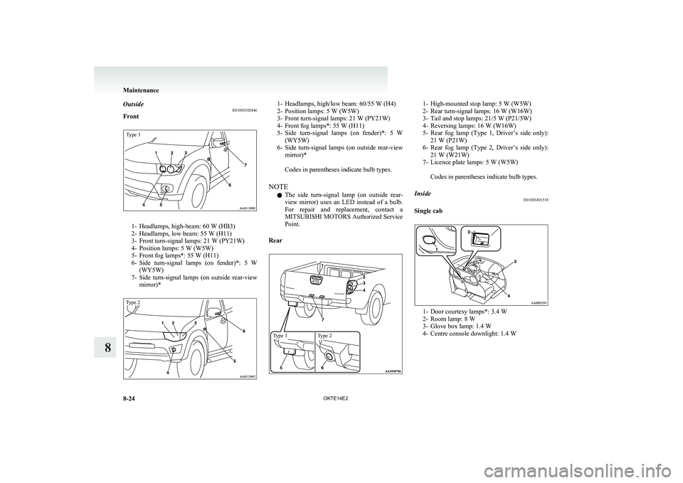
OutsideE01003302846
FrontType 1
1- Headlamps, high-beam: 60 W (HB3)
2- Headlamps, low beam: 55 W (H11)
3- Front turn-signal lamps: 21 W (PY21W)
4- Position lamps: 5 W (W5W)
5- Front fog lamps*: 55 W (H11)
6- Side turn-signal lamps (on fender)*: 5 W
(WY5W)
7- Side turn-signal lamps (on outside rear-view
mirror)*
Type 21- Headlamps, high/low beam: 60/55 W (H4)
2- Position lamps: 5 W (W5W)
3- Front turn-signal lamps: 21 W (PY21W)
4- Front fog lamps*: 55 W (H11)
5- Side turn-signal lamps (on fender)*: 5 W
(WY5W)
6- Side turn-signal lamps (on outside rear-view
mirror)*
Codes in parentheses indicate bulb types.
NOTE l The side turn-signal lamp (on outside rear-
view mirror) uses an LED instead of a bulb.
For repair and replacement, contact a
MITSUBISHI MOTORS Authorized Service
Point.
RearType 1Type 21- High-mounted stop lamp: 5 W (W5W)
2- Rear turn-signal lamps: 16 W (W16W)
3- Tail and stop lamps: 21/5 W (P21/5W)
4- Reversing lamps: 16 W (W16W)
5- Rear fog lamp (Type 1, Driver’s side only):
21 W (P21W)
6- Rear fog lamp (Type 2, Driver’s side only):
21 W (W21W)
7- Licence plate lamps: 5 W (W5W)
Codes in parentheses indicate bulb types.Inside E01003401518
Single cab
1- Door courtesy lamps*: 3.4 W
2- Room lamp: 8 W
3- Glove box lamp: 1.4 W
4- Centre console downlight: 1.4 W
Maintenance
8-24 OKTE14E2
8
Page 318 of 362
2.To install the bulb, perform the removal
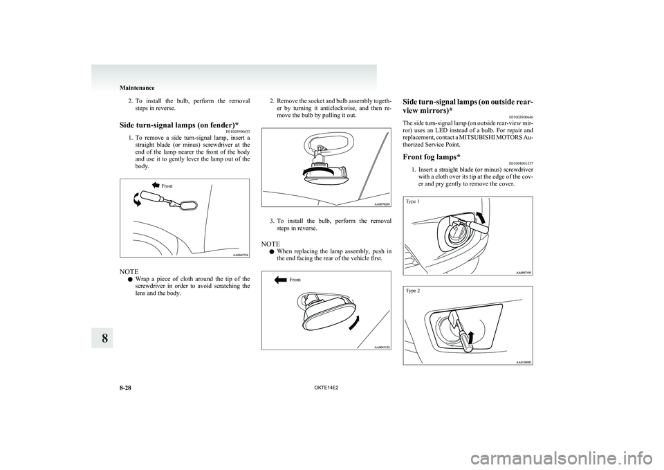
steps in reverse.Side turn-signal lamps (on fender)* E01003900633
1.To remove a side turn-signal lamp, insert a
straight blade (or minus) screwdriver at the
end of the lamp nearer the front of the body
and use it to gently lever the lamp out of the
body.
Front
NOTE
l Wrap a piece of cloth around the tip of the
screwdriver in order to avoid scratching the
lens and the body.
2. Remove the socket and bulb assembly togeth-
er by turning it anticlockwise, and then re-
move the bulb by pulling it out.
3. To install the bulb, perform the removal
steps in reverse.
NOTE l When replacing the lamp assembly, push in
the end facing the rear of the vehicle first.
FrontSide turn-signal lamps (on outside rear-
view mirrors)* E01003900646
The side turn-signal lamp (on outside rear-view mir-
ror) uses an LED instead of a bulb. For repair and
replacement, contact a MITSUBISHI MOTORS Au-
thorized Service Point.Front fog lamps* E01004001537
1.Insert a straight blade (or minus) screwdriver
with a cloth over its tip at the edge of the cov-
er and pry gently to remove the cover.
Type 1Type 2
Maintenance
8-28 OKTE14E2
8
Page 350 of 362
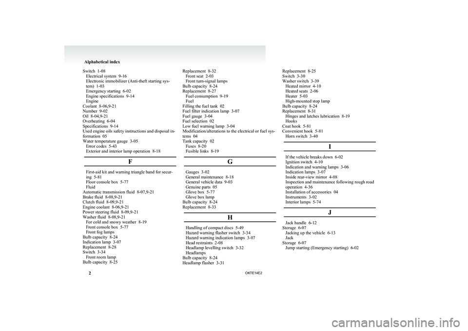
Switch 1-08
Electrical system 9-16
Electronic immobilizer (Anti-theft starting sys-
tem) 1-03
Emergency starting 6-02
Engine specifications 9-14
Engine
Coolant 8-06,9-21
Number 9-02
Oil 8-04,9-21
Overheating 6-04
Specifications 9-14
Used engine oils safety instructions and disposal in-
formation 05
Water temperature gauge 3-05 Error codes 5-43
Exterior and interior lamp operation 8-18
FFirst-aid kit and warning triangle band for secur-
ing 5-81
Floor console box 5-77
Fluid
Automatic transmission fluid
8-07,9-21
Brake fluid 8-08,9-21
Clutch fluid 8-09,9-21
Engine coolant 8-06,9-21
Power steering fluid 8-09,9-21
Washer fluid 8-08,9-21 For cold and snowy weather 8-19
Front console box 5-77
Front fog lamps
Bulb capacity 8-24
Indication lamp 3-07
Replacement 8-28
Switch 3-34 Front room lamp
Bulb capacity 8-25 Replacement 8-32
Front seat 2-03
Front turn-signal lamps
Bulb capacity
8-24
Replacement 8-27 Fuel consumption 9-19
Fuel
Filling the fuel tank 02
Fuel filter indication lamp 3-07
Fuel gauge 3-04
Fuel selection 02
Low fuel warning lamp 3-04
Modification/alterations to the electrical or fuel sys-
tems 04
Tank capacity 02 Fuses 8-20
Fusible links 8-19
G Gauges 3-02
General maintenance
8-18
General vehicle data 9-03
Genuine parts 05
Glove box 5-77
Glove box lamp
Bulb capacity 8-24
Replacement 8-33
H Handling of compact discs 5-49
Hazard warning flasher switch 3-34
Hazard warning indication lamps
3-07
Head restraints 2-08
Headlamp levelling switch 3-32
Headlamps
Bulb capacity 8-24
Headlamp flasher 3-31 Replacement 8-25
Switch 3-30
Washer switch 3-39
Heated mirror 4-10
Heated seats 2-06
Heater 5-03
High-mounted stop lamp
Bulb capacity
8-24
Replacement 8-31 Hinges and latches lubrication 8-19
Hooks
Coat hook 5-81
Convenient hook 5-81 Horn switch 3-40
I If the vehicle breaks down 6-02
Ignition switch 4-10
Indication and warning lamps
3-06
Indication lamps 3-07
Inside rear-view mirror 4-08
Inspection and maintenance following rough road
operation 4-36
Installation of accessories 04
Instruments 3-02
Interior lamps 5-74
J Jack handle 6-12
Storage 6-07 Jacking up the vehicle
6-13
Jack
Storage 6-07 Jump starting (Emergency starting) 6-02 Alphabetical index
2 OKTE14E2
Page 351 of 362
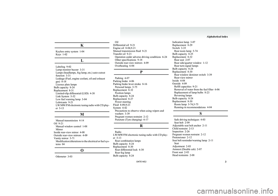
K
Keyless entry system 1-04
Keys 1-02
LLabeling 9-02
Lamp monitor buzzer
3-31
Lamps (headlamps, fog lamp, etc.) auto-cutout
function 3-31
Leakage (Fuel, engine coolant, oil and exhaust
gas) 8-18
Licence plate lamps
Bulb capacity 8-24
Replacement 8-31 Limited-slip differential (LSD) 4-38
Link System 5-52
Low fuel warning lamp 3-04
Lubricants 9-21
LW/MW/FM electronic tuning radio with CD play-
er 5-13
MManual transmission 4-14
Oil 9-21 Manual window control 1-08
Mirror
Inside rear-view mirror 4-08
Outside rear-view mirrors 4-09
Vanity mirror 5-71 Modification/alterations
to the electrical or fuel sys-
tems 04
OOdometer 3-03 Oil
Differential oil
9-21
Engine oil 8-04,9-21
Manual transmission fluid 9-21
Transfer oil 9-21 Operation under adverse driving conditions 6-24
Other specifications 9-18
Outside rear-view mirrors 4-09
Overheating 6-04
P Parking 4-07
Parking brake 4-06
Parking brake lever stroke
8-16
Personal lamps 5-75
Replacement 8-32 Position lamps
Bulb capacity 8-24
Replacement 8-27 Power steering
Fluid 8-09,9-21
System 4-42 Precautions to observe when using wipers and
washers 3-39
Pregnant women restraint 2-12
Puncture (Tyre changing) 6-17
R Radio
LW/MW/FM electronic tuning radio with CD play-
er 5-13 Rear combination lamps
Bulb capacity
8-24
Replacement 8-30 Rear differential lock 4-30
Rear fog lamp
Bulb capacity 8-24 Indication lamp 3-07
Replacement
8-29
Switch 3-35 Rear room lamp 5-74
Bulb capacity 8-25
Replacement 8-32 Rear seat 2-07
Rear side/quarter window 1-12
Rear turn-signal lamps
Bulb capacity 8-24
Replacement 8-30 Rear window demister switch 3-39
Rear-view mirror
Inside 4-08
Outside 4-09 Refill capacities 9-21
Removal of water from the fuel filter 6-06
Replacement of lamp bulbs 8-23
Reversing lamps
Bulb capacity 8-24
Replacement 8-30 Room lamp 5-74,5-75
Running-in recommendations 4-04
S Safe driving techniques 4-03
Seat belt 2-09
Adjustable seat belt anchor
2-11
Child restraint 2-13
Inspection 2-26
Pregnant women restraint 2-12
Pretensioner 2-12
Seat belt reminder/warning lamp 2-11 Seat
Adjustment 2-03
Armrest (Double cab) 2-07
Front seat 2-03
Head restraints 2-08 Alphabetical index
3OKTE14E2