MITSUBISHI L200 2014 Owner's Manual (in English)
Manufacturer: MITSUBISHI, Model Year: 2014, Model line: L200, Model: MITSUBISHI L200 2014Pages: 362, PDF Size: 20.97 MB
Page 261 of 362
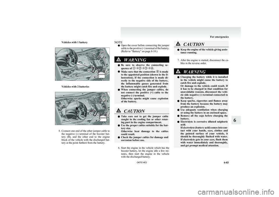
Vehicles with 1 battery
Vehicles with 2 batteries
5.Connect one end of the other jumper cable to
the negative (-) terminal of the booster bat-
tery (B), and the other end to the engine
block of the vehicle with the discharged bat-
tery at the point farthest from the battery.
NOTE
l Open the cover before connecting the jumper
cable to the positive (+) terminal of the battery.
(Refer to “Battery” on page 8-10.)WARNINGl Be sure to observe the connecting se-
quence of .
l Make sure that the connection is made
to the appointed position (shown in the il-
lustration). If the connection is made di-
rectly to the negative side of the battery,
the inflammable gasses generated from
the battery might catch fire and explode.
l When connecting the jumper cables, do
not connect the positive (+) cable to the
negative (-) terminal.
Otherwise sparks might cause explosion
of the battery.
CAUTIONl Take care not to get the jumper cable
caught in the cooling fan or other rotat-
ing part in the engine compartment.
l Use the proper cables suitable for the bat-
tery size.
Otherwise heat damage to the cables
could result.
l Check the jumper cables for damage and
corrosion before use.
6. Start the engine in the vehicle which has the
booster battery, let the engine idle a few mi-
nutes, then start the engine in the vehicle
with the discharged battery.
CAUTIONl Keep the engine of the vehicle giving assis-
tance running.
7. After the engine is started, disconnect the ca-
bles in the reverse order.
WARNINGl Charging the battery while it is installed
in the vehicle might cause the battery to
catch fire and explode.
Or damage to the vehicle could result. If
it has to be charged in that condition for
unavoidable reasons, disconnect the vehi-
cle side negative (-) terminal connected to
the battery.
l Keep sparks, cigarettes and flames away
from the battery because the battery may
produce an explosion.
l Use adequate ventilation when charging
or using the battery in an enclosed space.
l Remove all the caps before charging the
battery.
l Electrolyte is corrosive diluted sulphuric
acid.
If electrolyte (battery acid) comes into con-
tact with your hands, eyes, clothes and
the painted surface of your vehicle, it
should be thoroughly flushed with water.
If electrolyte gets in your eyes, flush them
with water immediately and thoroughly,
and get prompt medical attention.
For emergencies
6-03
OKTE14E2
6
Page 262 of 362
CAUTIONlDo not attempt to start the engine by pull-
ing or pushing the vehicle.
It could damage your vehicle.
l Always wear protective eye goggles when
working near the battery.
l Keep the battery out of the reach of chil-
dren.
NOTE
l On vehicles with anti-lock brake system, if
the vehicle is put in motion without fully
charging the battery, it might cause the loss
of smooth engine operation and the antilock
brake warning lamp to illuminate.
Refer to “Anti-lock brake system (ABS)” on
page 4-39.
Engine overheating E00800602777
If the water temperature gauge indication remains
in the overheating zone for a long time, the engine
may be overheating. If this occurs, take the follow-
ing corrective measures: 1. Stop the vehicle in a safe place.
2. Check whether steam is coming from the en-
gine compartment.
[ If steam does not come from the engine com-
partment]
With the engine still running, raise the bon-
net to ventilate the engine compartment.
[If steam is coming from the engine compart-
ment]
Stop the engine, and when the steam stops,
raise the bonnet to ventilate the engine com-
partment. Restart the engine.WARNINGl Do not open the bonnet while steam is com-
ing from the engine compartment. It
could cause steam or hot water to spurt
out, causing burns. Hot water could spurt
out even when there is no steam coming
out, and some parts will be very hot. Be
very careful when opening the bonnet.
l Be careful of hot steam, which could be
blowing off the reserve tank cap.
l Do not attempt to remove the radiator
cap while the engine is hot.
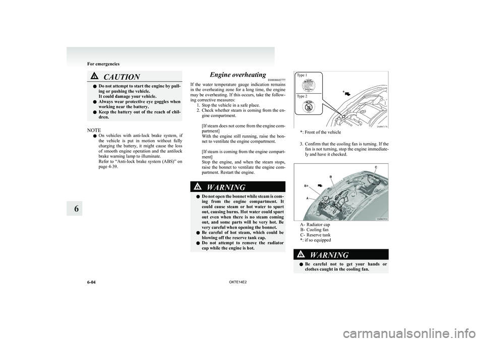
*: Front of the vehicle
3. Confirm that the cooling fan is turning. If the
fan is not turning, stop the engine immediate-
ly and have it checked.
A- Radiator cap B- Cooling fan
C- Reserve tank
*: if so equipped
WARNINGl Be careful not to get your hands or
clothes caught in the cooling fan.
For emergencies
6-04 OKTE14E2
6 Type 1
Type 2
Page 263 of 362
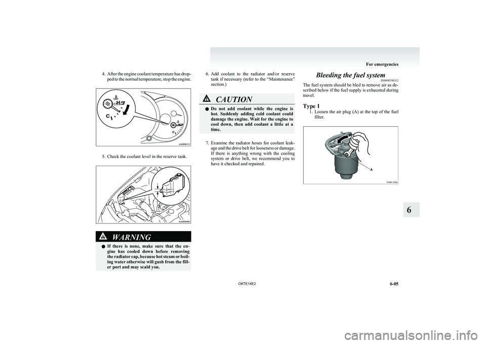
4.After the engine coolant temperature has drop-
ped to the normal temperature, stop the engine.
5. Check the coolant level in the reserve tank.
WARNINGl If there is none, make sure that the en-
gine has cooled down before removing
the radiator cap, because hot steam or boil-
ing water otherwise will gush from the fill-
er port and may scald you.6. Add coolant to the radiator and/or reserve
tank if necessary (refer to the “Maintenance”
section.)CAUTIONl Do not add coolant while the engine is
hot. Suddenly adding cold coolant could
damage the engine. Wait for the engine to
cool down, then add coolant a little at a
time.
7. Examine the radiator hoses for coolant leak-
age and the drive belt for looseness or damage.
If there is anything wrong with the cooling
system or drive belt, we recommend you to
have it checked and repaired.
Bleeding the fuel system E00800700312
The fuel system should be bled to remove air as de-
scribed below if the fuel supply is exhausted during
travel.
Type 1 1.Loosen the air plug (A) at the top of the fuel
filter.
For emergencies
6-05
OKTE14E2
6
Page 264 of 362
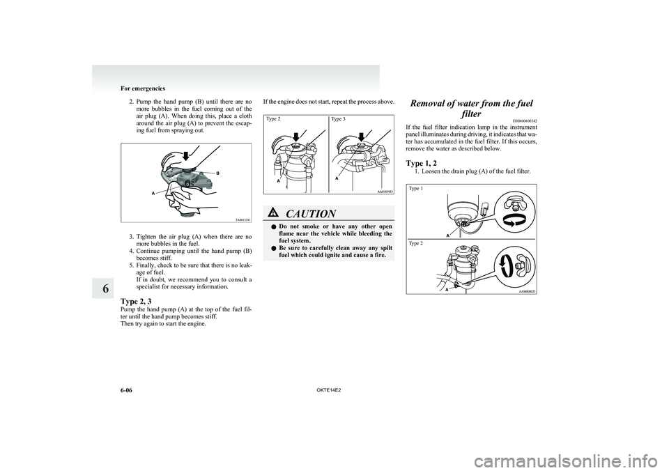
2.Pump the hand pump (B) until there are no
more bubbles in the fuel coming out of the
air plug (A). When doing this, place a cloth
around the air plug (A) to prevent the escap-
ing fuel from spraying out.
3. Tighten the air plug (A) when there are no
more bubbles in the fuel.
4. Continue pumping until the hand pump (B)
becomes stiff.
5. Finally, check to be sure that there is no leak- age of fuel.
If in doubt, we recommend you to consult a
specialist for necessary information.
Type 2, 3
Pump the hand pump (A) at the top of the fuel fil-
ter until the hand pump becomes stiff.
Then try again to start the engine.
If the engine does not start, repeat the process above.Type 2Type 3
CAUTIONl Do not smoke or have any other open
flame near the vehicle while bleeding the
fuel system.
l Be sure to carefully clean away any spilt
fuel which could ignite and cause a fire.Removal of water from the fuel
filterE00800800342
If the fuel filter indication lamp in the instrument
panel illuminates during driving, it indicates that wa-
ter has accumulated in the fuel filter. If this occurs,
remove the water as described below.
Type 1, 2 1. Loosen the drain plug (A) of the fuel filter.
Type 1Type 2
For emergencies
6-06 OKTE14E2
6
Page 265 of 362
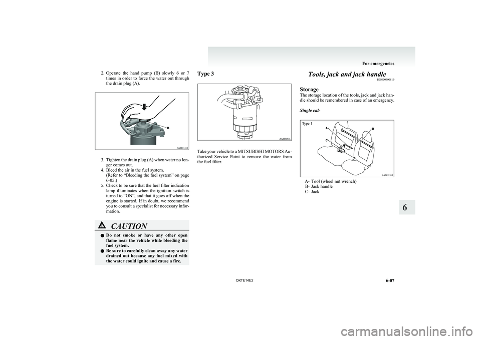
2.Operate the hand pump (B) slowly 6 or 7
times in order to force the water out through
the drain plug (A).
3. Tighten the drain plug (A) when water no lon-
ger comes out.
4. Bleed the air in the fuel system. (Refer to “Bleeding the fuel system” on page
6-05.)
5. Check to be sure that the fuel filter indication lamp illuminates when the ignition switch is
turned to “ON”, and that it goes off when the
engine is started. If in doubt, we recommend
you to consult a specialist for necessary infor-
mation.
CAUTIONl Do not smoke or have any other open
flame near the vehicle while bleeding the
fuel system.
l Be sure to carefully clean away any water
drained out because any fuel mixed with
the water could ignite and cause a fire.Type 3
Take your vehicle to a MITSUBISHI MOTORS Au-
thorized Service Point to remove the water from
the fuel filter.
Tools, jack and jack handle E00800900819
Storage
The storage location of the tools, jack and jack han-
dle should be remembered in case of an emergency.
Single cab
Type 1
A- Tool (wheel nut wrench) B- Jack handle
C- Jack
For emergencies
6-07
OKTE14E2
6
Page 266 of 362
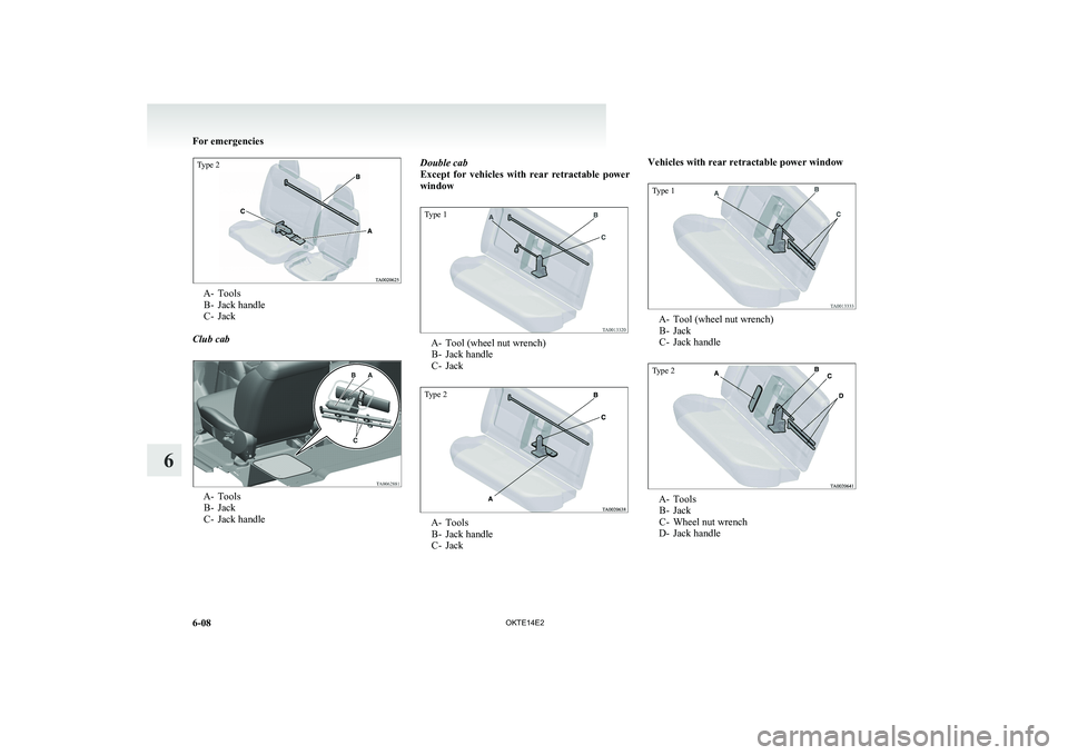
Type 2
A- ToolsB- Jack handle
C- Jack
Club cab
A- Tools B- Jack
C- Jack handle
Double cab
Except for vehicles with rear retractable power
windowType 1
A- Tool (wheel nut wrench) B- Jack handle
C- Jack
Type 2
A- Tools B- Jack handle
C- Jack
Vehicles with rear retractable power windowType 1
A- Tool (wheel nut wrench) B- Jack
C- Jack handle
Type 2
A- Tools B- Jack
C- Wheel nut wrench
D- Jack handle
For emergencies
6-08 OKTE14E2
6
Page 267 of 362
ToolsE00801900382
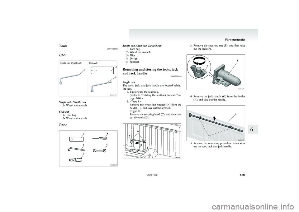
Type 1Single cab, Double cabClub cab
Single cab, Double cab 1- Wheel nut wrench
Club cab 1- Tool bag
2- Wheel nut wrench
Type 2
Single cab, Club cab, Double cab 1- Tool bag
2- Wheel nut wrench
3- Plier
4- Driver
5- SpannerRemoving and storing the tools, jack
and jack handle E00802300240
Single cab
The tools, jack, and jack handle are located behind
the seat. 1. Tip forward the seatback.(Refer to “Folding the seatback forward” on
page 2-06.)
2.
holder (B), and take out the wrench.
Remove the securing band (C), and then take
out the tools (D).
3. Remove the securing nut (E), and then take
out the jack (F).
4. Remove the jack handle (G) from the holder
(H), and take out the handle.
5. Reverse the removing procedure when stor-
ing the tool, jack and jack handle.
For emergencies
6-09
OKTE14E2
6
Page 268 of 362
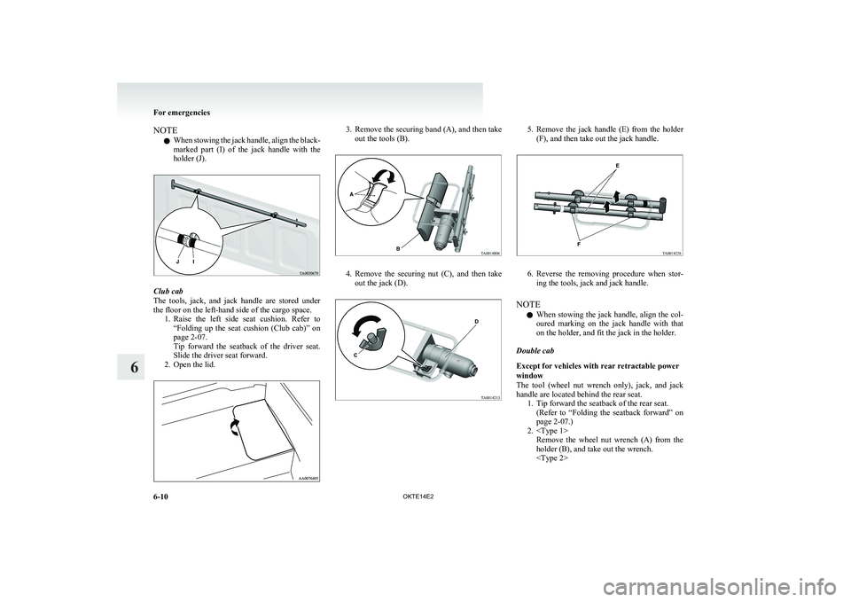
NOTEl When stowing the jack handle, align the black-
marked part (I) of the jack handle with the
holder (J).
Club cab
The tools, jack, and jack handle are stored under
the floor on the left-hand side of the cargo space. 1.Raise the left side seat cushion. Refer to
“ Folding up the seat cushion (Club cab)” on
page 2-07.
Tip forward the seatback of the driver seat.
Slide the driver seat forward.
2. Open the lid.
3. Remove the securing band (A), and then take
out the tools (B).
4. Remove the securing nut (C), and then take
out the jack (D).
5. Remove the jack handle (E) from the holder
(F), and then take out the jack handle.
6. Reverse the removing procedure when stor-
ing the tools, jack and jack handle.
NOTE l When stowing the jack handle, align the col-
oured marking on the jack handle with that
on the holder, and fit the jack in the holder.
Double cab
Except for vehicles with rear retractable power
window
The tool (wheel nut wrench only), jack, and jack
handle are located behind the rear seat. 1. Tip forward the seatback of the rear seat.(Refer to “Folding the seatback forward” on
page 2-07.)
2.
holder (B), and take out the wrench.
For emergencies
6-10 OKTE14E2
6
Page 269 of 362
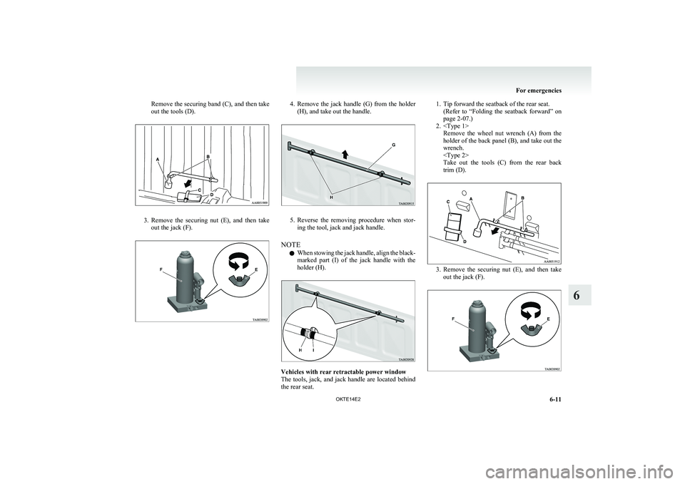
Remove the securing band (C), and then take
out the tools (D).
3. Remove the securing nut (E), and then take
out the jack (F).
4. Remove the jack handle (G) from the holder
(H), and take out the handle.
5. Reverse the removing procedure when stor-
ing the tool, jack and jack handle.
NOTE l When stowing the jack handle, align the black-
marked part (I) of the jack handle with the
holder (H).
Vehicles with rear retractable power window
The tools, jack, and jack handle are located behind
the rear seat.
1. Tip forward the seatback of the rear seat. (Refer to “Folding the seatback forward” on
page 2-07.)
2.
holder of the back panel (B), and take out the
wrench.
Take out the tools (C) from the rear back
trim (D).
3. Remove the securing nut (E), and then take
out the jack (F).
For emergencies
6-11
OKTE14E2
6
Page 270 of 362
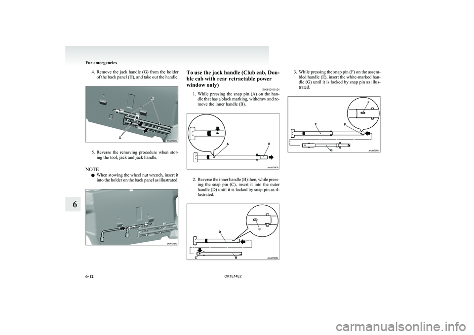
4.Remove the jack handle (G) from the holder
of the back panel (H), and take out the handle.
5. Reverse the removing procedure when stor-
ing the tool, jack and jack handle.
NOTE l When stowing the wheel nut wrench, insert it
into the holder on the back panel as illustrated.
To use the jack handle (Club cab, Dou-
ble cab with rear retractable power
window only) E00802400124
1. While pressing the snap pin (A) on the han-
dle that has a black marking, withdraw and re-
move the inner handle (B).
2. Reverse the inner handle (B) then, while press-
ing the snap pin (C), insert it into the outer
handle (D) until it is locked by snap pin as il-
lustrated.
3. While pressing the snap pin (F) on the assem-
bled handle (E), insert the white-marked han-
dle (G) until it is locked by snap pin as illus-
trated.
For emergencies
6-12 OKTE14E2
6