turn signal MITSUBISHI L200 2015 Owner's Manual (in English)
[x] Cancel search | Manufacturer: MITSUBISHI, Model Year: 2015, Model line: L200, Model: MITSUBISHI L200 2015Pages: 418, PDF Size: 25.8 MB
Page 4 of 418
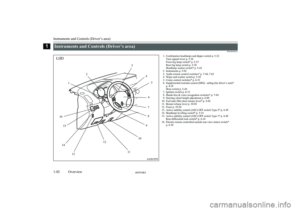
Instruments and Controls (Driver’s area)E00100108331
1LHD23456789101112131415161. Combination headlamps and dipper switch p. 5-32Turn-signals lever p. 5-36
Front fog lamp switch* p. 5-37
Rear fog lamp switch p. 5-38
Headlamp washer switch* p. 5-42
2. Instruments p. 5-02
3. Audio remote control switches* p. 7-44, 7-63
4. Wiper and washer switch p. 5-38
5. Cruise control switches* p. 6-51
6. Supplemental restraint system (SRS) - airbag (for driver’s seat)* p. 4-28
Horn switch p. 5-44
7. Ignition switch p. 6-12
8. Hands-free & voice recognition switches* p. 7-84
9. Steering wheel height adjustment p. 6-09
10. Fuel tank filler door release lever* p. 2-02
11. Bonnet release lever p. 10-03
12. Fuses p. 10-20
13. Active stability control (ASC) OFF switch Type 2* p. 6-49
14. Headlamp levelling switch* p. 5-35
15. Active stability control (ASC) OFF switch Type 1* p. 6-49 Rear differential lock switch* p. 6-34
16. Electric remote-controlled outside rear-view mirror switch* p. 6-10
Instruments and Controls (Driver’s area)
1-02OKTE15E3Overview1
Page 5 of 418
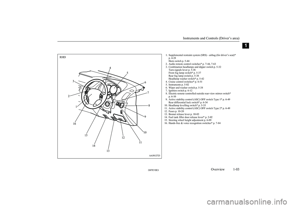
1. Supplemental restraint system (SRS) - airbag (for driver’s seat)*p. 4-28
Horn switch p. 5-44
2. Audio remote control switches* p. 7-44, 7-63
3. Combination headlamps and dipper switch p. 5-32 Turn-signals lever p. 5-36
Front fog lamp switch* p. 5-37
Rear fog lamp switch p. 5-38
Headlamp washer switch* p. 5-42
4. Cruise control switches* p. 6-51
5. Instruments p. 5-02
6. Wiper and washer switch p. 5-38
7. Ignition switch p. 6-12
8. Electric remote-controlled outside rear-view mirror switch* p. 6-10
9. Active stability control (ASC) OFF switch Type 1* p. 6-49 Rear differential lock switch* p. 6-34
10. Headlamp levelling switch* p. 5-35
11. Active stability control (ASC) OFF switch Type 2* p. 6-49
12. Fuses p. 10-20
13. Bonnet release lever p. 10-03
14. Fuel tank filler door release lever* p. 2-02
15. Steering wheel height adjustment p. 6-09
16. Hands-free & voice recognition switches* p. 7-84
Instruments and Controls (Driver’s area)
1-03OKTE15E3Overview1RHD
Page 18 of 418
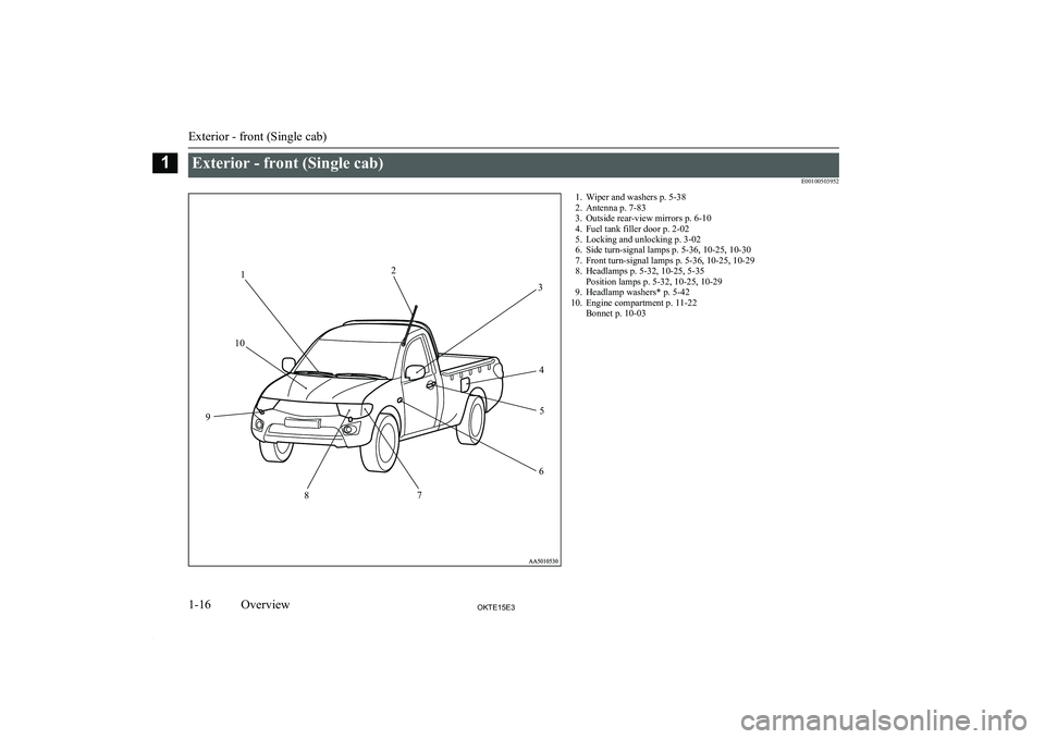
Exterior - front (Single cab)E001005039521. Wiper and washers p. 5-38
2. Antenna p. 7-83
3. Outside rear-view mirrors p. 6-10
4. Fuel tank filler door p. 2-02
5. Locking and unlocking p. 3-02
6. Side turn-signal lamps p. 5-36, 10-25, 10-30
7. Front turn-signal lamps p. 5-36, 10-25, 10-29
8. Headlamps p. 5-32, 10-25, 5-35 Position lamps p. 5-32, 10-25, 10-29
9. Headlamp washers* p. 5-42
10. Engine compartment p. 11-22 Bonnet p. 10-03
Exterior - front (Single cab)
1-16OKTE15E3Overview112
3
45
6
7
8
9
10
Page 19 of 418
Exterior - rear (Single cab)E00100505419
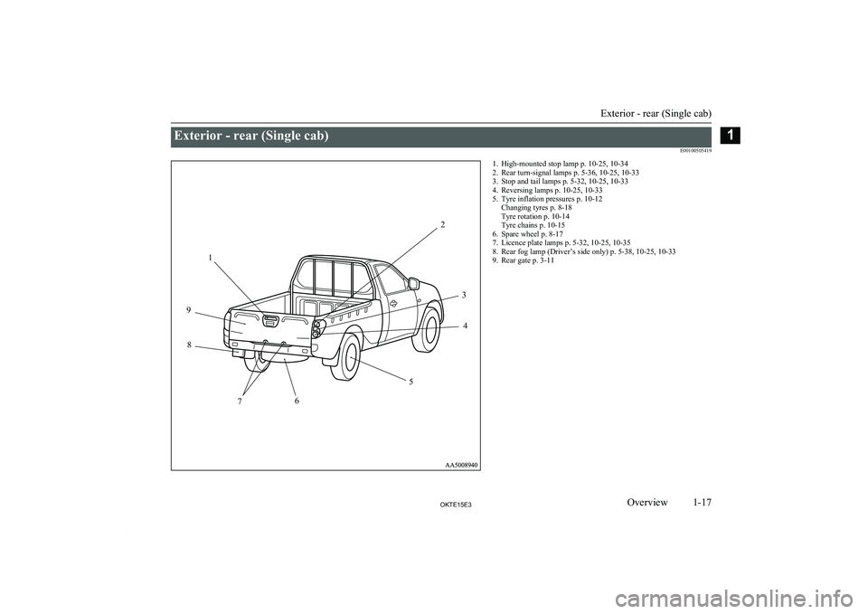
1234567891. High-mounted stop lamp p. 10-25, 10-34
2. Rear turn-signal lamps p. 5-36, 10-25, 10-33
3. Stop and tail lamps p. 5-32, 10-25, 10-33
4. Reversing lamps p. 10-25, 10-33
5. Tyre inflation pressures p. 10-12 Changing tyres p. 8-18
Tyre rotation p. 10-14
Tyre chains p. 10-15
6. Spare wheel p. 8-17
7. Licence plate lamps p. 5-32, 10-25, 10-35
8. Rear fog lamp (Driver’s side only) p. 5-38, 10-25, 10-33
9. Rear gate p. 3-11
Exterior - rear (Single cab)
1-17OKTE15E3Overview1
Page 20 of 418
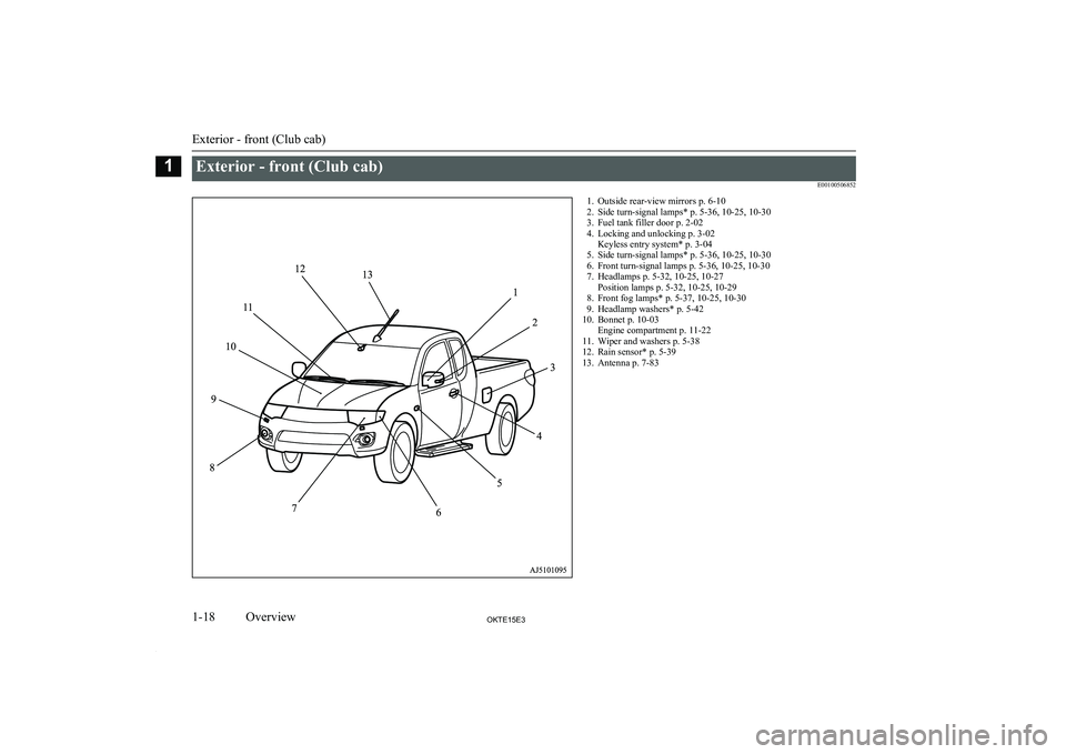
Exterior - front (Club cab)E001005068521. Outside rear-view mirrors p. 6-10
2. Side turn-signal lamps* p. 5-36, 10-25, 10-30
3. Fuel tank filler door p. 2-02
4. Locking and unlocking p. 3-02 Keyless entry system* p. 3-04
5. Side turn-signal lamps* p. 5-36, 10-25, 10-30
6. Front turn-signal lamps p. 5-36, 10-25, 10-30
7. Headlamps p. 5-32, 10-25, 10-27 Position lamps p. 5-32, 10-25, 10-29
8. Front fog lamps* p. 5-37, 10-25, 10-30
9. Headlamp washers* p. 5-42
10. Bonnet p. 10-03 Engine compartment p. 11-22
11. Wiper and washers p. 5-38
12. Rain sensor* p. 5-39
13. Antenna p. 7-83
Exterior - front (Club cab)
1-18OKTE15E3Overview1
Page 21 of 418
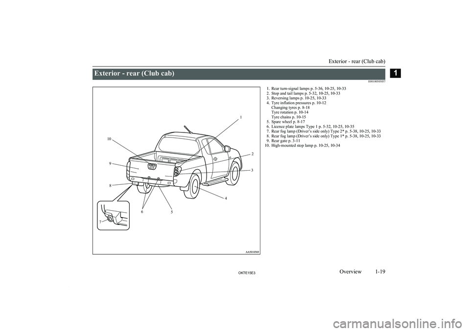
Exterior - rear (Club cab)E001005050571. Rear turn-signal lamps p. 5-36, 10-25, 10-33
2. Stop and tail lamps p. 5-32, 10-25, 10-33
3. Reversing lamps p. 10-25, 10-33
4. Tyre inflation pressures p. 10-12 Changing tyres p. 8-18
Tyre rotation p. 10-14
Tyre chains p. 10-15
5. Spare wheel p. 8-17
6. Licence plate lamps Type 1 p. 5-32, 10-25, 10-35
7. Rear fog lamp (Driver’s side only) Type 2* p. 5-38, 10-25, 10-33
8. Rear fog lamp (Driver’s side only) Type 1* p. 5-38, 10-25, 10-33
9. Rear gate p. 3-11
10. High-mounted stop lamp p. 10-25, 10-34
Exterior - rear (Club cab)
1-19OKTE15E3Overview112
3
4
5
6
7 8
9
10
Page 22 of 418

Exterior - front (Double cab)E001005068651. Antenna* p. 7-832. Sunroof* p. 3-14
3. Antenna* p. 7-83
4. Outside rear-view mirrors p. 6-10
5. Side turn-signal lamps* p. 5-36, 10-25, 10-30
6. Fuel tank filler door p. 2-02
7. Locking and unlocking p. 3-02 Keyless entry system* p. 3-04
8. Side turn-signal lamps* p. 5-36, 10-25, 10-30
9. Front turn-signal lamps p. 5-36, 10-25, 10-30
10. Headlamps p. 5-32, 10-25, 10-27 Position lamps p. 5-32, 10-25, 10-29
11. Front fog lamps* p. 5-37, 10-25, 10-30
12. Headlamp washers* p. 5-42
13. Bonnet p. 10-03 Engine compartment p. 11-22
14. Wiper and washers p. 5-38
15. Rain sensor* p. 5-39
Exterior - front (Double cab)
1-20OKTE15E3Overview1
Page 23 of 418
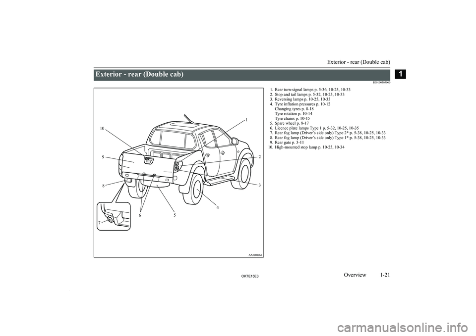
Exterior - rear (Double cab)E001005050601. Rear turn-signal lamps p. 5-36, 10-25, 10-33
2. Stop and tail lamps p. 5-32, 10-25, 10-33
3. Reversing lamps p. 10-25, 10-33
4. Tyre inflation pressures p. 10-12 Changing tyres p. 8-18
Tyre rotation p. 10-14
Tyre chains p. 10-15
5. Spare wheel p. 8-17
6. Licence plate lamps Type 1 p. 5-32, 10-25, 10-35
7. Rear fog lamp (Driver’s side only) Type 2* p. 5-38, 10-25, 10-33
8. Rear fog lamp (Driver’s side only) Type 1* p. 5-38, 10-25, 10-33
9. Rear gate p. 3-11
10. High-mounted stop lamp p. 10-25, 10-34
Exterior - rear (Double cab)
1-21OKTE15E3Overview112
3
4
5
6
7 8
9
10
Page 32 of 418
KeysE00300101608
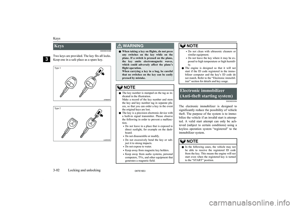
Two keys are provided. The key fits all locks.
Keep one in a safe place as a spare key.
Type 1Type 2
WARNINGl When taking a key on flights, do not press
any switches on the key while on the plane. If a switch is pressed on the plane,the key emits electromagnetic waves,which could adversely affect the plane’s
flight operation.
When carrying a key in a bag, be careful that no switches on the key can be easily
pressed by mistake.NOTEl The key number is stamped on the tag as in-
dicated in the illustration.
Make a record of the key number and store the key and key number tag in separate pla-
ces, so that you can order a key in the event the original keys are lost.
l The key is a precision electronic device with
a built-in signal transmitter. Please observe the following in order to prevent a malfunc-tion.
• Do not leave in a place that is exposed to
direct sunlight, for example on the dash- board.
• Do not disassemble or modify.
• Do not excessively bend the key or sub-
ject it to strong impacts.
• Do not expose to water.
• Keep away from magnetic key holders.
• Keep away from audio systems, personal
computers, TVs, and other equipment that generates a magnetic field.NOTE• Do not clean with ultrasonic cleaners or
similar equipment.
• Do not leave the key where it may be ex-
posed to high temperature or high humidi-
ty.
l The engine is designed so that it will not
start if the ID code registered in the immo-
bilizer computer and the key’s ID code do
not match. Refer to the “Electronic immobil- izer” section for details and key usage.Electronic immobilizer
(Anti-theft starting system) E00300203094
The electronic immobilizer is designed tosignificantly reduce the possibility of vehicle
theft. The purpose of the system is to immo-
bilize the vehicle if an invalid start is attemp-
ted. A valid start attempt can only be ach- ieved (subject to certain conditions) using akeyless operation system “registered” to theimmobilizer system.
NOTEl In the following cases, the vehicle may not
be able to receive the registered ID code from the key. This means the engine will not
start even when the registered key is turned
to the “START” position.
Keys
3-02OKTE15E3Locking and unlocking3
Page 34 of 418
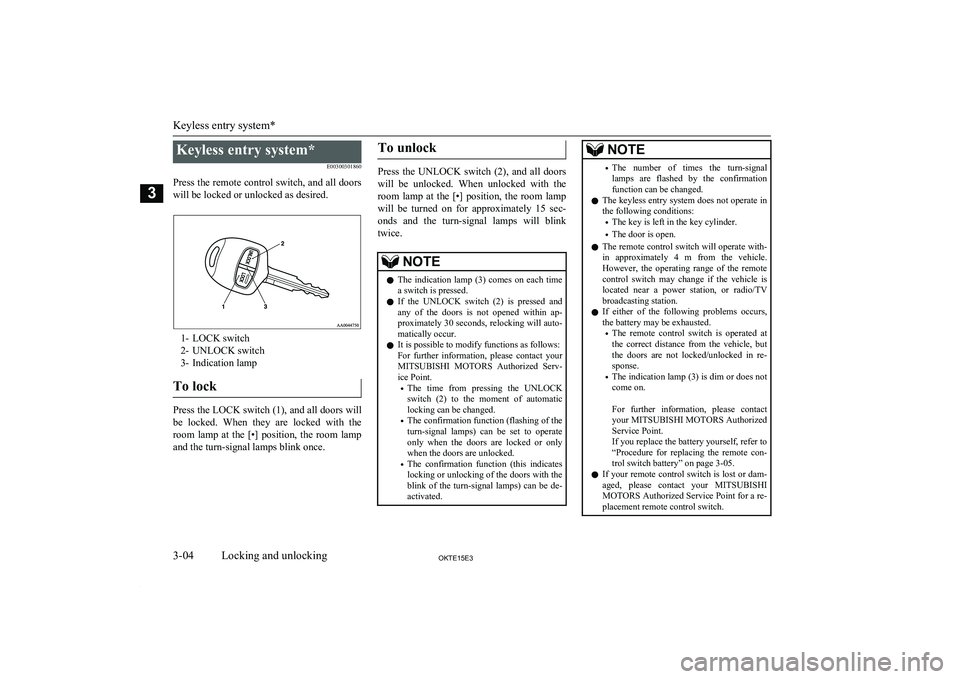
Keyless entry system*E00300301860
Press the remote control switch, and all doors will be locked or unlocked as desired.
1- LOCK switch
2- UNLOCK switch
3- Indication lamp
To lock
Press the LOCK switch (1), and all doors will
be locked. When they are locked with the room lamp at the [•] position, the room lampand the turn-signal lamps blink once.
To unlock
Press the UNLOCK switch (2), and all doors
will be unlocked. When unlocked with the
room lamp at the [•] position, the room lamp will be turned on for approximately 15 sec-
onds and the turn-signal lamps will blink twice.
NOTEl The indication lamp (3) comes on each time
a switch is pressed.
l If the UNLOCK switch (2) is pressed and
any of the doors is not opened within ap- proximately 30 seconds, relocking will auto-matically occur.
l It is possible to modify functions as follows:
For further information, please contact your MITSUBISHI MOTORS Authorized Serv-
ice Point.
• The time from pressing the UNLOCK
switch (2) to the moment of automatic locking can be changed.
• The confirmation function (flashing of the
turn-signal lamps) can be set to operate
only when the doors are locked or only when the doors are unlocked.
• The confirmation function (this indicates
locking or unlocking of the doors with the
blink of the turn-signal lamps) can be de- activated.NOTE• The number of times the turn-signal
lamps are flashed by the confirmation function can be changed.
l The keyless entry system does not operate in
the following conditions:
• The key is left in the key cylinder.
• The door is open.
l The remote control switch will operate with-
in approximately 4 m from the vehicle.
However, the operating range of the remote control switch may change if the vehicle is
located near a power station, or radio/TV broadcasting station.
l If either of the following problems occurs,
the battery may be exhausted.
• The remote control switch is operated at
the correct distance from the vehicle, but
the doors are not locked/unlocked in re- sponse.
• The indication lamp (3) is dim or does not
come on.
For further information, please contact
your MITSUBISHI MOTORS Authorized
Service Point.
If you replace the battery yourself, refer to
“Procedure for replacing the remote con- trol switch battery” on page 3-05.
l If your remote control switch is lost or dam-
aged, please contact your MITSUBISHI
MOTORS Authorized Service Point for a re-
placement remote control switch.
Keyless entry system*
3-04OKTE15E3Locking and unlocking3