headlamp MITSUBISHI L200 2017 (in English) Owner's Guide
[x] Cancel search | Manufacturer: MITSUBISHI, Model Year: 2017, Model line: L200, Model: MITSUBISHI L200 2017Pages: 426, PDF Size: 14.12 MB
Page 356 of 426
During cold weather
If the temperatures in your area drop belowfreezing, there is the danger that the coolant
in the engine or radiator could freeze and
cause severe damage to the engine and/or ra- diator. Add a sufficient amount of anti-freeze to the coolant to prevent it from freezing.The concentration should be checked before the start of cold weather and anti-freeze add-
ed to the system if necessary.
Washer fluid
E01000702113
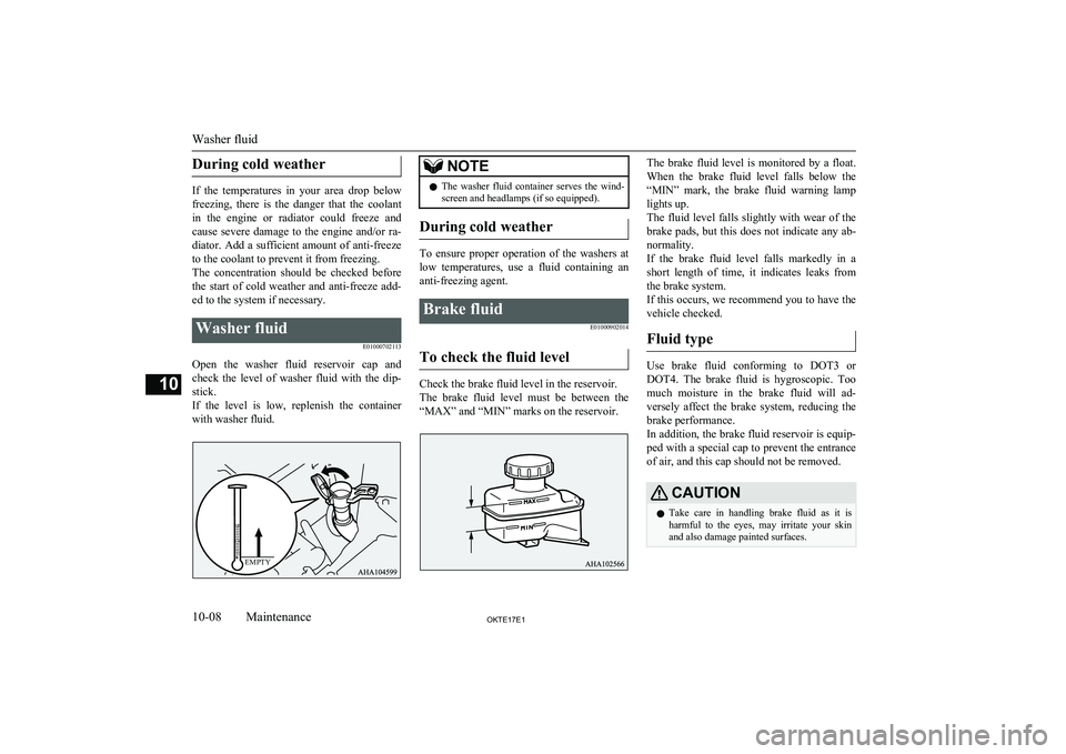
Open the washer fluid reservoir cap andcheck the level of washer fluid with the dip- stick.
If the level is low, replenish the container with washer fluid.
NOTEl The washer fluid container serves the wind-
screen and headlamps (if so equipped).
During cold weather
To ensure proper operation of the washers at
low temperatures, use a fluid containing ananti-freezing agent.
Brake fluid
E01000902014
To check the fluid level
Check the brake fluid level in the reservoir.
The brake fluid level must be between the “MAX” and “MIN” marks on the reservoir.
The brake fluid level is monitored by a float.
When the brake fluid level falls below the “MIN” mark, the brake fluid warning lamp
lights up.
The fluid level falls slightly with wear of the brake pads, but this does not indicate any ab-
normality.
If the brake fluid level falls markedly in a short length of time, it indicates leaks from
the brake system.
If this occurs, we recommend you to have the vehicle checked.
Fluid type
Use brake fluid conforming to DOT3 or
DOT4. The brake fluid is hygroscopic. Too
much moisture in the brake fluid will ad- versely affect the brake system, reducing the brake performance.
In addition, the brake fluid reservoir is equip-
ped with a special cap to prevent the entrance
of air, and this cap should not be removed.
CAUTIONl Take care in handling brake fluid as it is
harmful to the eyes, may irritate your skin
and also damage painted surfaces.
Washer fluid
10-08OKTE17E1Maintenance10EMPTY
Page 367 of 426
No.Sym-bolElectrical sys- temCa-
pacity16Relay7.5 A17Heated seat20 A18Option10 A19Heated door mirror7.5 A20Windscreen wiper20 A21Reversing lamps7.5 A22Demister30 A23Heater30 A24Power seat40 A *25Radio10 A26Electronic con-
trolled unit20 A*: Fusible link
l Some fuses may not be installed on your
vehicle, depending on the vehicle model
or specifications.
l The table above shows the main equip-
ment corresponding to each fuse.
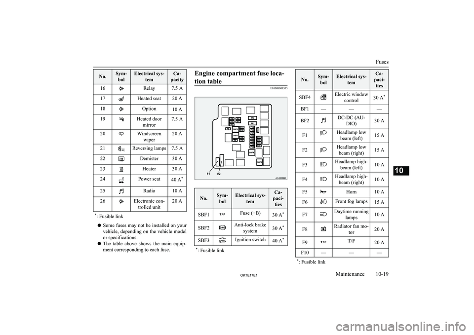
Engine compartment fuse loca-
tion table
E01008001955
No.Sym- bolElectrical sys- temCa-
paci- tiesSBF1Fuse (+B)30 A *SBF2Anti-lock brake
system30 A *SBF3Ignition switch40 A**
: Fusible link
No.Sym-
bolElectrical sys- temCa-
paci- tiesSBF4Electric window control30 A *BF1———BF2DC-DC (AU-
DIO)30 AF1Headlamp lowbeam (left)15 AF2Headlamp lowbeam (right)15 AF3Headlamp high- beam (left)10 AF4Headlamp high-beam (right)10 AF5Horn10 AF6Front fog lamps15 AF7Daytime running lamps10 AF8Radiator fan mo- tor20 AF9T/F20 AF10———*: Fusible link
Fuses
10-19OKTE17E1Maintenance10
Page 368 of 426
No.Sym-bolElectrical sys- temCa-
paci- tiesF11Headlamp wash- er20 AF12Stop lamps
(Brake lamps)15 AF13Ignition coil10 AF14Engine control7.5 AF15Alternator7.5 AF16Hazard warning flasher15 AF17Automatic trans-mission20 AF18Air conditioning20 A
F19
ETV15 AFuel line heater20 AF20Starter7.5 AF21———F22Fuel pump15 AF23Engine20 A*: Fusible link
No.Sym-
bolElectrical sys- temCa-
paci- tiesF24———#1—Spare fuse20 A#2—Spare fuse30 A* : Fusible link
l Some fuses may not be installed on your
vehicle, depending on the vehicle model
or specifications.
l The table above shows the main equip-
ment corresponding to each fuse.
The fuse block does not contain spare 7.5 A ,
10 A or 15 A fuses. If one of these fuses burns out, substitute with the following fuse.7.5 A: Outside rear-view mirrors
10 A: Option
15 A: Cigarette lighter
When using a substitute fuse, replace with a
fuse of the correct capacity as soon as possi-
ble.
Identification of fuse
E01008100366
Ca-
pacityColour7.5 ABrownCa-
pacityColour10 ARed15 ABlue20 AYellow30 AGreen (fuse type) / Pink (fusible link type)40 AGreen (fusible link type)Fuse replacement
E01007801943
1.Before replacing a fuse, always turn off
the electrical circuit concerned and place
the ignition switch in the “LOCK” posi-
tion or put the operation mode in OFF.
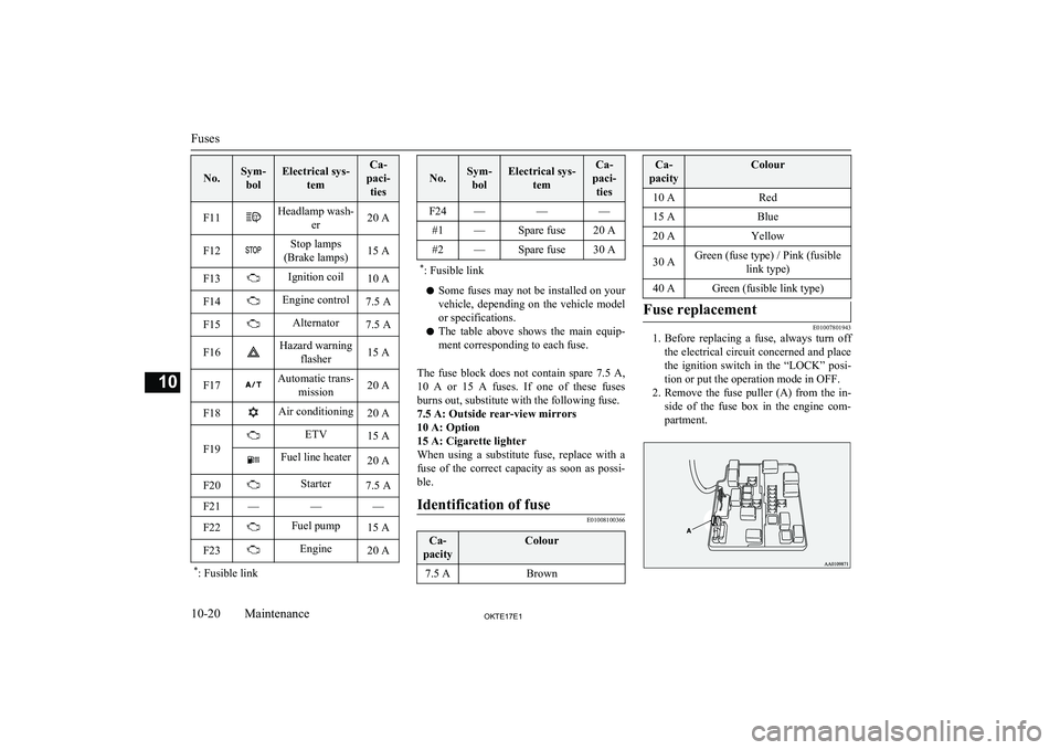
2. Remove the fuse puller (A) from the in-
side of the fuse box in the engine com- partment.
Fuses
10-20OKTE17E1Maintenance10
Page 370 of 426
CAUTIONlNever hold the halogen lamp bulb with a
bare hand, dirty glove, etc.
The oil from your hand could cause the bulb to break the next time the headlamps are op-
erated.
If the glass surface is dirty, it must be cleaned with alcohol, paint thinner, etc., and
refit it after drying it thoroughly.
l Do not install commercially available LED-
type bulbs.
Commercially available LED-type bulbs
could adversely affect the operation of the vehicle, such as by preventing the lamps and
other vehicle equipment from operating properly.
NOTEl If you are unsure of how to carry out the
work as required, we recommend you to consult a specialist.
l Be careful not to scratch the vehicle body
when removing a lamp and lens.NOTEl When it rains or when the vehicle has been
washed, the inside of the lens sometimes be-
comes foggy. This is the same phenomenon as when window glass mists up on a humid
day, and does not indicate a functional prob- lem. When the lamp is switched on, the heat
will remove the fog. However, if water gath- ers inside the lamp, we recommend you tohave the lamp checked.Bulb location and capacity
E01003201415
When replacing a bulb, use a new bulb with
the same wattage and colour.
OutsideE01003304967
Front
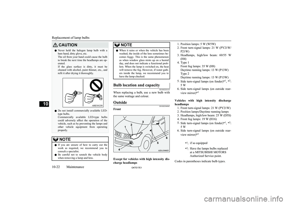
Except for vehicles with high intensity dis-charge headlamps
1. Position lamps: 5 W (W5W)
2. Front turn-signal lamps: 21 W (PY21W/
P21W)
3. Headlamps, high/low beam: 60/55 W
(H4)
4. Type 1 Front fog lamps: 35 W (H8)
Daytime running lamps: 13 W (P13W)
Type 2
Daytime running lamps: 13 W (P13W)
5. Side turn-signal lamps (on fender)* 1
, * 2
:
5 W
6. Side turn-signal lamps (on outside rear-
view mirror)* 1
Vehicles with high intensity discharge
headlamps 1. Front turn-signal lamps: 21 W (PY21W)
2. Position lamps/Daytime running lamps
3. Headlamps, high/low beam: 25 W (D5S) 4. Front fog lamps: 19 W (H16)
5. Side turn-signal lamps (on fender)* 1
, * 2
:
5 W
6. Side turn-signal lamps (on outside rear-
view mirror)* 1*
1
:if so equipped* 2
:Have the lamps bulbs replaced
at a MITSUBISHI MOTORS
Authorized Service point.
Codes in parentheses indicate bulb types.
Replacement of lamp bulbs
10-22OKTE17E1Maintenance10
Page 371 of 426
WARNINGlAlways consult a specialist when repair-
ing or replacing the bulbs of high intensi-
ty discharge headlamps.
This is because the power circuit, bulbs
and electrodes generate a high voltage that could cause an electric shock.NOTEl It is not possible to repair or replace only the
bulb for the side turn-signal lamp (on fend-
er).
Check with a MITSUBISHI MOTORS Au-
thorized Service point when the lamp needs to be repaired or replaced.Rear
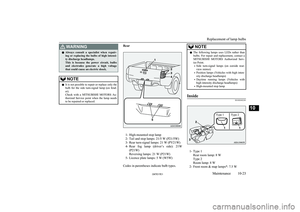
1- High-mounted stop lamp
2- Tail and stop lamps: 21/5 W (P21/5W) 3- Rear turn-signal lamps: 21 W (PY21W)4- Rear fog lamp (driver’s side): 21W
(P21W)
Reversing lamps: 21 W (P21W)
5- Licence plate lamps: 5 W (W5W)
Codes in parentheses indicate bulb types.
NOTEl The following lamps uses LEDs rather than
bulbs. For repair and replacement, contact a
MITSUBISHI MOTORS Authorized Serv-
ice Point.
• Side turn-signal lamps (on outside rear-
view mirror)
• Position lamps (Vehicles with high inten-
sity discharge headlamps)
• Daytime running lamps (Vehicles with
high intensity discharge headlamps)
• High-mounted stop lampInside
E01003403381
1- Type 1
Rear room lamp: 8 W
Type 2
Room lamp: 8 W
2- Front room & map lamps*: 7.5 W
Replacement of lamp bulbs
10-23OKTE17E1Maintenance10 Type 1 Type 2
Page 372 of 426
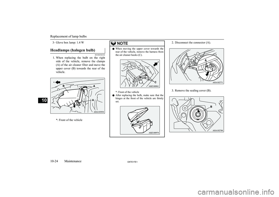
3- Glove box lamp: 1.4 WHeadlamps (halogen bulb)
E01003502532
1.When replacing the bulb on the right
side of the vehicle, remove the clamps
(A) of the air cleaner filter and move the upper cover (B) towards the rear of the
vehicle.
*: Front of the vehicle
NOTEl When moving the upper cover towards the
rear of the vehicle, remove the harness fromthe air cleaner hooks (C).
*: Front of the vehicle
l After replacing the bulb, make sure that the
hinges at the front of the vehicle are firmly
set.
2. Disconnect the connector (A).
3. Remove the sealing cover (B).
Replacement of lamp bulbs
10-24OKTE17E1Maintenance10
Page 373 of 426
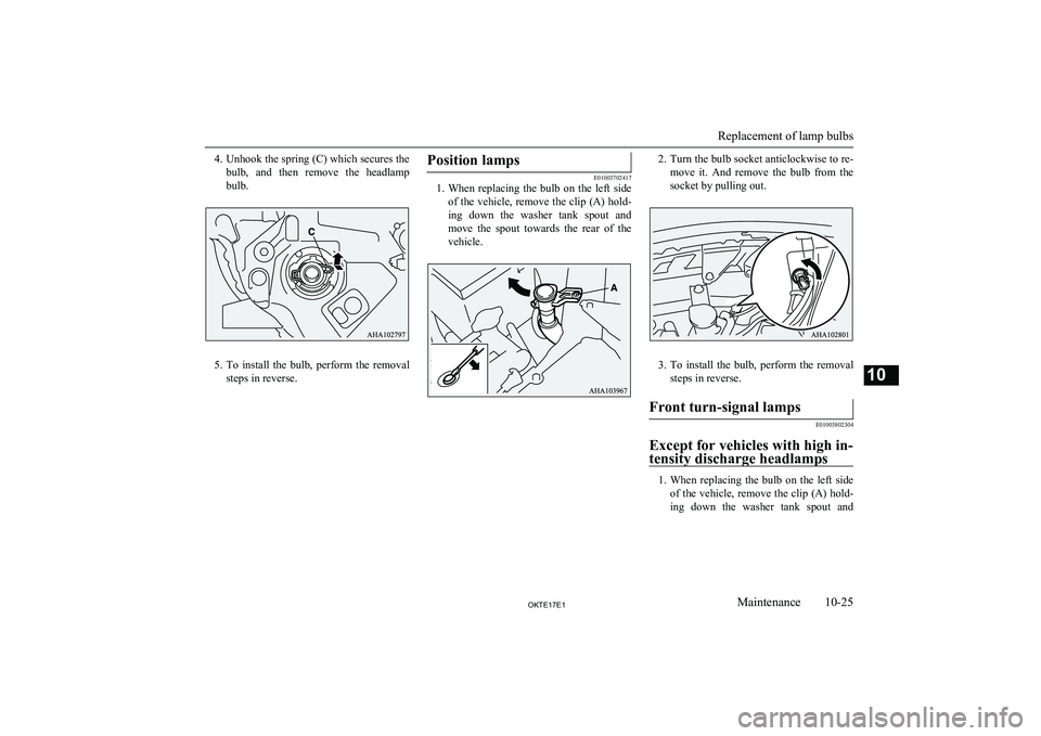
4.Unhook the spring (C) which secures the
bulb, and then remove the headlamp bulb.
5. To install the bulb, perform the removal
steps in reverse.
Position lamps
E01003702417
1. When replacing the bulb on the left side
of the vehicle, remove the clip (A) hold-
ing down the washer tank spout and
move the spout towards the rear of the vehicle.
2. Turn the bulb socket anticlockwise to re-
move it. And remove the bulb from the
socket by pulling out.
3. To install the bulb, perform the removal
steps in reverse.
Front turn-signal lamps
E01003802304
Except for vehicles with high in- tensity discharge headlamps
1. When replacing the bulb on the left side
of the vehicle, remove the clip (A) hold- ing down the washer tank spout and
Replacement of lamp bulbs
10-25OKTE17E1Maintenance10
Page 374 of 426
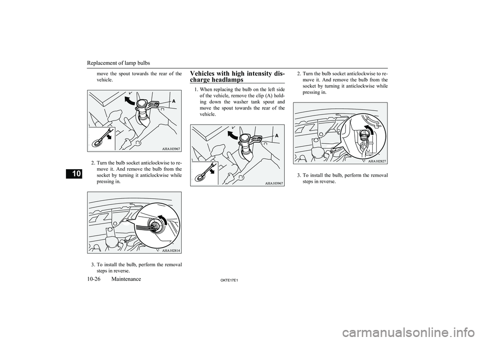
move the spout towards the rear of the
vehicle.
2. Turn the bulb socket anticlockwise to re-
move it. And remove the bulb from the
socket by turning it anticlockwise while pressing in.
3. To install the bulb, perform the removal
steps in reverse.
Vehicles with high intensity dis-
charge headlamps
1. When replacing the bulb on the left side
of the vehicle, remove the clip (A) hold- ing down the washer tank spout and
move the spout towards the rear of the vehicle.
2. Turn the bulb socket anticlockwise to re-
move it. And remove the bulb from the
socket by turning it anticlockwise while pressing in.
3. To install the bulb, perform the removal
steps in reverse.
Replacement of lamp bulbs
10-26OKTE17E1Maintenance10
Page 379 of 426
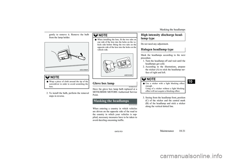
gently to remove it. Remove the bulb
from the lamp holder.NOTEl Wrap a piece of cloth around the tip of the
screwdriver in order to avoid scratching the
lens.
2. To install the bulb, perform the removal
steps in reverse.
NOTEl When installing the lens, fit the two tabs on
one side of the lens into the holes on the ve-hicle side before fitting the two tabs on the opposite side of the lens into the holes on the
vehicle side.Glove box lamp
E01006101516
Have the glove box lamp bulb replaced at a
MITSUBISHI MOTORS Authorized Service
Point.
Masking the headlamps
E01011601085
When entering a country in which vehiclesare driven on the opposite side of the road to the country in which your vehicles is sup-plied, necessary measures have to be taken to
avoid dazzling oncoming traffic.
High intensity discharge head-
lamp type
Do not need any adjustment.
Halogen headlamp type
Mask the headlamps according to the next
procedure. 1. Turn the headlamp off and wait until the
headlamps got cold.
2. According to the illustrations, prepare
the sticker (A) to stick the headlamp sur-
face of right and left.
NOTEl Use a sticker with a light blocking effect
enough.
Using of a sticker without a light blocking
effect will not acquire a blocking effect.
3. Seeing from the headlamp front, position
(C) of the sticker and the central mark
(B) of the headlamp and stick a sticker along the vertical dotted line.
Masking the headlamps
10-31OKTE17E1Maintenance10
Page 380 of 426
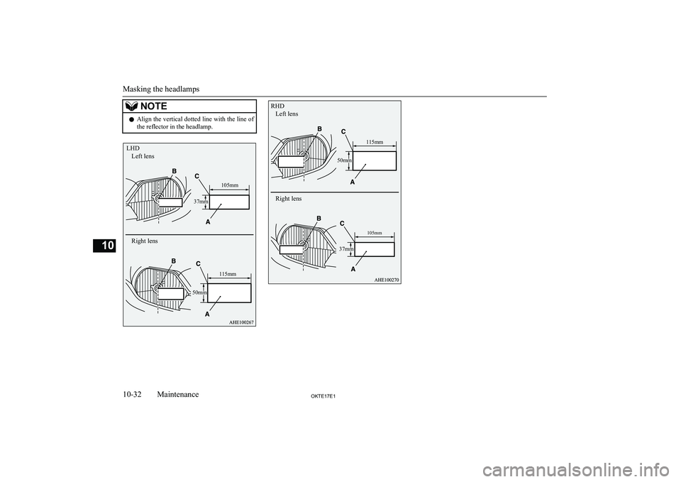
NOTElAlign the vertical dotted line with the line of
the reflector in the headlamp.
Masking the headlamps
10-32OKTE17E1Maintenance10 LHDLeft lens
Right lens
115mm105mm
37mm
50mm RHDLeft lens
Right lens
105mm
37mm
50mm
115mm