wheel nut MITSUBISHI L200 2017 Owner's Manual (in English)
[x] Cancel search | Manufacturer: MITSUBISHI, Model Year: 2017, Model line: L200, Model: MITSUBISHI L200 2017Pages: 426, PDF Size: 14.12 MB
Page 42 of 426
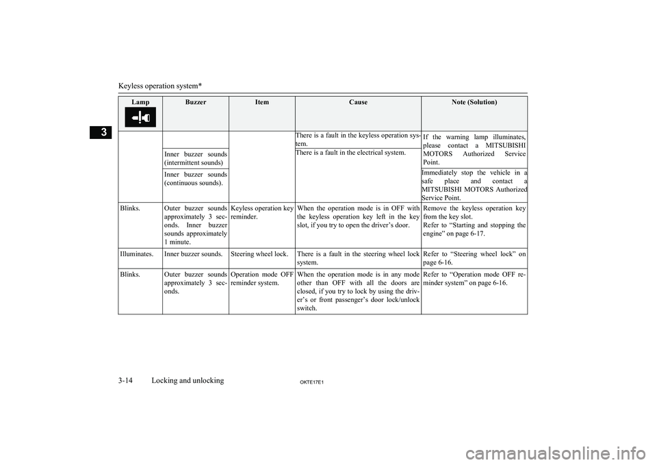
LampBuzzerItemCauseNote (Solution)There is a fault in the keyless operation sys-tem.If the warning lamp illuminates,please contact a MITSUBISHI
MOTORS Authorized Service
Point.Immediately stop the vehicle in a safe place and contact a
MITSUBISHI MOTORS Authorized
Service Point.Inner buzzer sounds
(intermittent sounds)There is a fault in the electrical system.Inner buzzer sounds (continuous sounds).Blinks.Outer buzzer sounds approximately 3 sec-onds. Inner buzzer sounds approximately
1 minute.Keyless operation key reminder.When the operation mode is in OFF withthe keyless operation key left in the key
slot, if you try to open the driver’s door.Remove the keyless operation key from the key slot.
Refer to “Starting and stopping the
engine” on page 6-17.Illuminates.Inner buzzer sounds.Steering wheel lock.There is a fault in the steering wheel lock
system.Refer to “Steering wheel lock” on
page 6-16.Blinks.Outer buzzer sounds approximately 3 sec-onds.Operation mode OFF reminder system.When the operation mode is in any mode
other than OFF with all the doors are closed, if you try to lock by using the driv- er’s or front passenger’s door lock/unlock
switch.Refer to “Operation mode OFF re- minder system” on page 6-16.
Keyless operation system*
3-14OKTE17E1Locking and unlocking3
Page 131 of 426
All vehicle’s electrical devices can be operat-ed.
The indication lamp on the engine switch il-
luminates green. The indication lamp turns
off when the engine is running.NOTEl Your vehicle is equipped with an electronic
immobilizer..
To start the engine, the ID code transmitted
by the transponder inside the key must match the code registered in the immobilizer
computer. Refer to “Electronic immobilizer
(Anti-theft starting system)” on page 3-03.Changing the operation mode
E00631901142
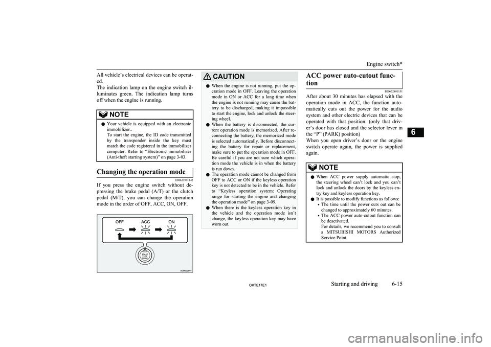
If you press the engine switch without de-
pressing the brake pedal (A/T) or the clutch
pedal (M/T), you can change the operation
mode in the order of OFF, ACC, ON, OFF.
CAUTIONl When the engine is not running, put the op-
eration mode in OFF. Leaving the operation mode in ON or ACC for a long time when
the engine is not running may cause the bat- tery to be discharged, making it impossible
to start the engine, lock and unlock the steer- ing wheel.
l When the battery is disconnected, the cur-
rent operation mode is memorized. After re- connecting the battery, the memorized modeis selected automatically. Before disconnect-
ing the battery for repair or replacement,
make sure to put the operation mode in OFF. Be careful if you are not sure which opera-
tion mode the vehicle is in when the battery
is run down.
l The operation mode cannot be changed from
OFF to ACC or ON if the keyless operation
key is not detected to be in the vehicle. Refer
to “Keyless operation system: Operating range for starting the engine and changing
the operation mode” on page 3-09.
l When there is the keyless operation key in
the vehicle and the operation mode isn’t
change, the keyless operation key may have worn out.ACC power auto-cutout func-
tion
E00632801151
After about 30 minutes has elapsed with the
operation mode in ACC, the function auto-
matically cuts out the power for the audio system and other electric devices that can be
operated with that position. (only that driv- er’s door has closed and the selector lever in
the “P” (PARK) position)
When you open driver’s door or the engine
switch operate again, the power is supplied
again.
NOTEl When ACC power supply automatic stop,
the steering wheel can’t lock and you can’t lock and unlock the doors by the keyless en-
try key and keyless operation key.
l It is possible to modify functions as follows:
• The time until the power cuts out can be
changed to approximately 60 minutes.
• The ACC power auto-cutout function can
be deactivated.
For details, we recommend you to consult
a MITSUBISHI MOTORS Authorized
Service Point.
Engine switch*
6-15OKTE17E1Starting and driving6
Page 324 of 426
2.Operate the hand pump (B) slowly 6 or 7
times in order to force the water out
through the drain plug (A).
3. Tighten the drain plug (A) when water
no longer comes out.
4. Bleed the air in the fuel system. (Refer to “Bleeding the fuel system” onpage 8-11.)
5. Check to be sure that the fuel filter indi-
cation lamp illuminates when the igni- tion switch is turned to “ON” or the op-
eration mode is put in ON, and that it
goes off when the engine is started. If in
doubt, we recommend you to consult a specialist for necessary information.
CAUTIONl Do not smoke or have any other open flame
near the vehicle while bleeding the fuel sys-
tem.
l Be sure to carefully clean away any water
drained out because any fuel mixed with the water could ignite and cause a fire.Tools, jack and jack handle
E00800902695
Storage
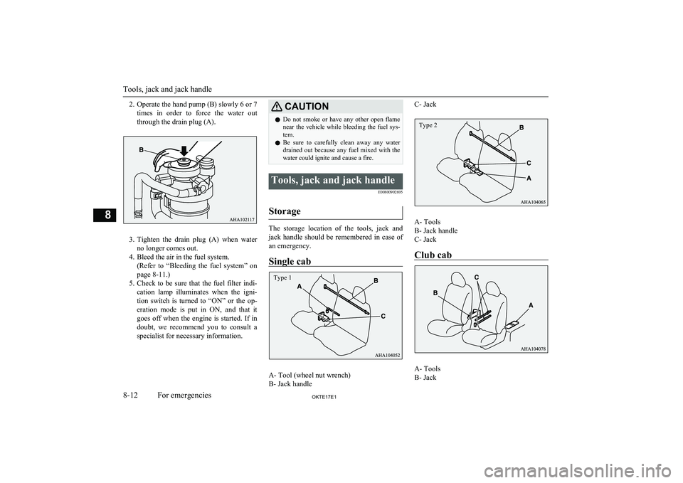
The storage location of the tools, jack andjack handle should be remembered in case ofan emergency.
Single cab
A- Tool (wheel nut wrench)
B- Jack handle
C- Jack
A- Tools
B- Jack handle
C- Jack
Club cab
A- Tools
B- Jack
Tools, jack and jack handle
8-12OKTE17E1For emergencies8 Type 1 Type 2
Page 325 of 426
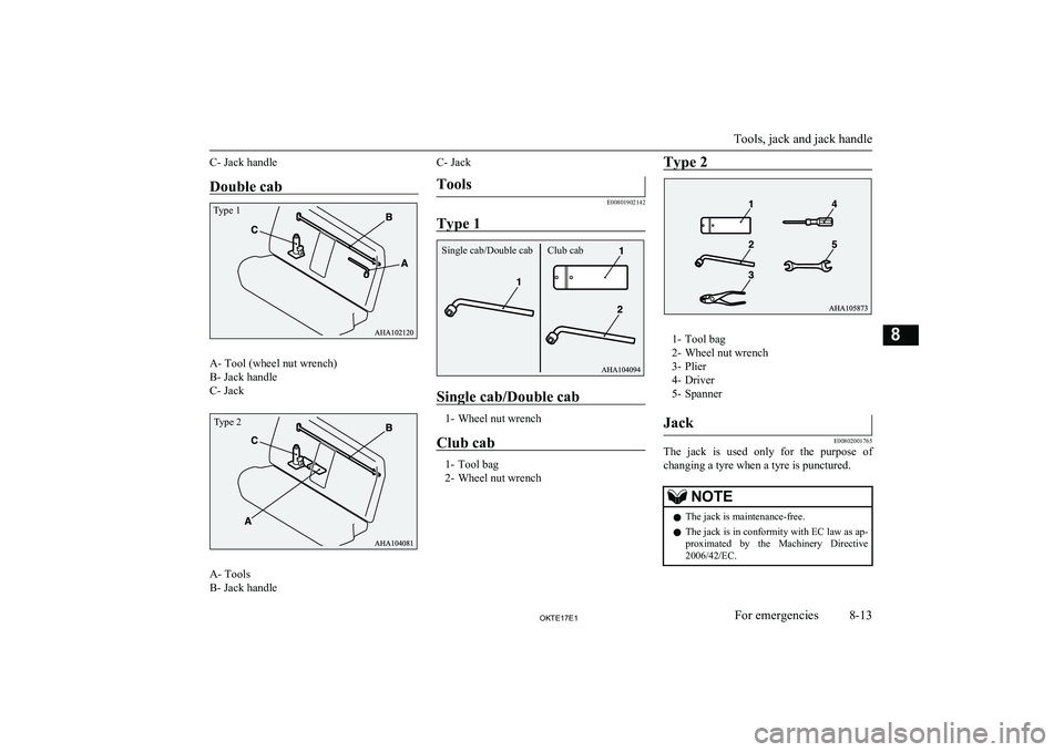
C- Jack handleDouble cab
A- Tool (wheel nut wrench)
B- Jack handle
C- Jack
A- Tools
B- Jack handle
C- JackTools
E00801902142
Type 1
Single cab/Double cab
1- Wheel nut wrench
Club cab
1- Tool bag
2- Wheel nut wrench
Type 2
1- Tool bag
2- Wheel nut wrench
3- Plier
4- Driver
5- Spanner
Jack
E00802001765
The jack is used only for the purpose of
changing a tyre when a tyre is punctured.
NOTEl The jack is maintenance-free.
l The jack is in conformity with EC law as ap-
proximated by the Machinery Directive
2006/42/EC.
Tools, jack and jack handle
8-13OKTE17E1For emergencies8Type 1 Type 2 Club cab
Single cab/Double cab
Page 326 of 426
NOTElThe EC declaration of conformity is attached
to the section “Declaration of Conformity” in the end of this owner’s manual.
• The business name, full address of the
manufacturer and of his authorized repre-sentative and the designation of the jack
are described in the EC declaration of conformity.Removing and storing the
tools, jack and jack handle
E00802301481
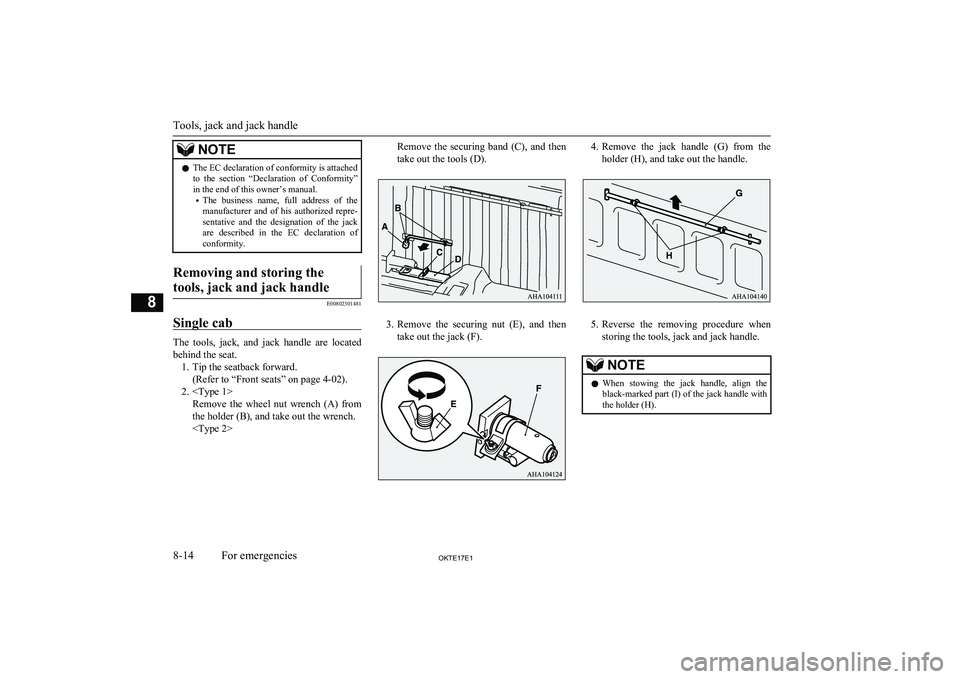
Single cab
The tools, jack, and jack handle are located
behind the seat. 1. Tip the seatback forward. (Refer to “Front seats” on page 4-02).
2.
Remove the securing band (C), and then
take out the tools (D).
3. Remove the securing nut (E), and then
take out the jack (F).
4. Remove the jack handle (G) from the
holder (H), and take out the handle.
5. Reverse the removing procedure when
storing the tools, jack and jack handle.
NOTEl When stowing the jack handle, align the
black-marked part (I) of the jack handle with
the holder (H).
Tools, jack and jack handle
8-14OKTE17E1For emergencies8
Page 328 of 426
NOTElWhen stowing the jack handle, align the col-
oured marking on the jack handle with that
on the holder, and fit the jack in the holder.
Double cab
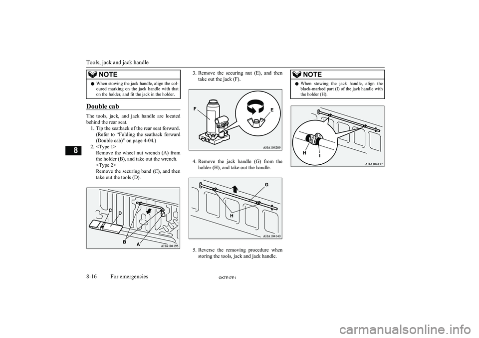
The tools, jack, and jack handle are located
behind the rear seat. 1. Tip the seatback of the rear seat forward. (Refer to “Folding the seatback forward
(Double cab)” on page 4-04.)
2.
Remove the securing band (C), and then
take out the tools (D).
3. Remove the securing nut (E), and then
take out the jack (F).
4. Remove the jack handle (G) from the
holder (H), and take out the handle.
5. Reverse the removing procedure when
storing the tools, jack and jack handle.
NOTEl When stowing the jack handle, align the
black-marked part (I) of the jack handle with
the holder (H).
Tools, jack and jack handle
8-16OKTE17E1For emergencies8
Page 330 of 426
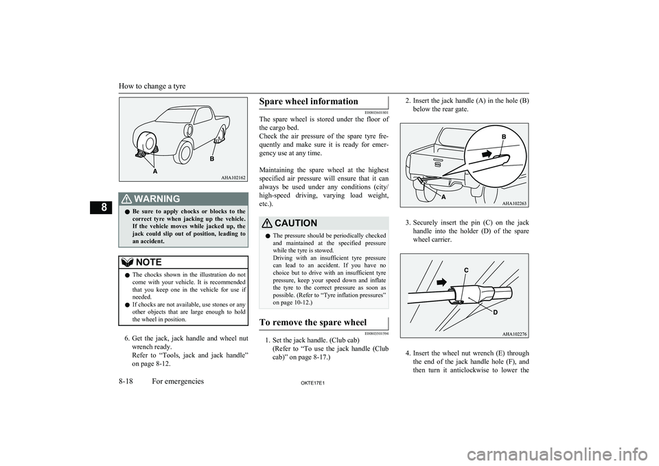
WARNINGlBe sure to apply chocks or blocks to the
correct tyre when jacking up the vehicle.If the vehicle moves while jacked up, the
jack could slip out of position, leading to
an accident.NOTEl The chocks shown in the illustration do not
come with your vehicle. It is recommended
that you keep one in the vehicle for use if needed.
l If chocks are not available, use stones or any
other objects that are large enough to hold the wheel in position.
6. Get the jack, jack handle and wheel nut
wrench ready.
Refer to “Tools, jack and jack handle” on page 8-12.
Spare wheel information
E00803601801
The spare wheel is stored under the floor of
the cargo bed.
Check the air pressure of the spare tyre fre-
quently and make sure it is ready for emer- gency use at any time.
Maintaining the spare wheel at the highest
specified air pressure will ensure that it can always be used under any conditions (city/ high-speed driving, varying load weight,
etc.).
CAUTIONl The pressure should be periodically checked
and maintained at the specified pressure while the tyre is stowed.
Driving with an insufficient tyre pressure
can lead to an accident. If you have no choice but to drive with an insufficient tyre
pressure, keep your speed down and inflate the tyre to the correct pressure as soon as
possible. (Refer to “Tyre inflation pressures”
on page 10-12.)To remove the spare wheel
E00803501594
1. Set the jack handle. (Club cab)
(Refer to “To use the jack handle (Clubcab)” on page 8-17.)
2. Insert the jack handle (A) in the hole (B)
below the rear gate.
3. Securely insert the pin (C) on the jack
handle into the holder (D) of the spare
wheel carrier.
4. Insert the wheel nut wrench (E) through
the end of the jack handle hole (F), and
then turn it anticlockwise to lower the
How to change a tyre
8-18OKTE17E1For emergencies8
Page 331 of 426
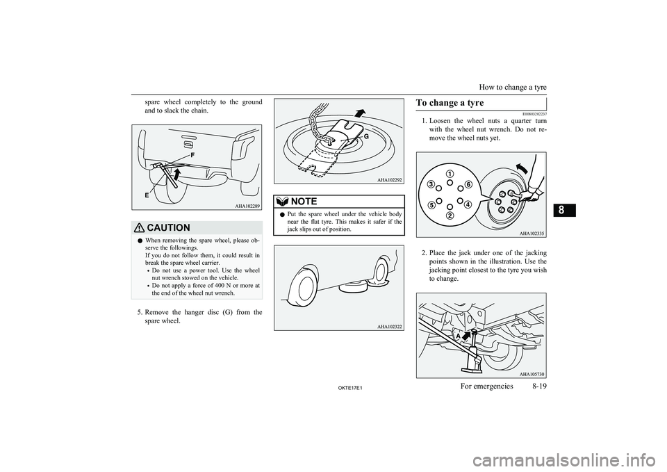
spare wheel completely to the ground
and to slack the chain.CAUTIONl When removing the spare wheel, please ob-
serve the followings.
If you do not follow them, it could result in
break the spare wheel carrier.
• Do not use a power tool. Use the wheel
nut wrench stowed on the vehicle.
• Do not apply a force of 400 N or more at
the end of the wheel nut wrench.
5. Remove the hanger disc (G) from the
spare wheel.
NOTEl Put the spare wheel under the vehicle body
near the flat tyre. This makes it safer if the jack slips out of position.To change a tyre
E00803202237
1. Loosen the wheel nuts a quarter turn
with the wheel nut wrench. Do not re- move the wheel nuts yet.
2. Place the jack under one of the jacking
points shown in the illustration. Use the jacking point closest to the tyre you wish
to change.
How to change a tyre
8-19OKTE17E1For emergencies8
Page 333 of 426
WARNINGlStop jacking up the vehicle as soon as the
tyre is raised off the ground. It is danger-
ous to raise the vehicle any higher.
l Do not get under your vehicle while using
the jack.
l Do not bump the raised vehicle or leave it
sitting on the jack for a long time. Both are very dangerous.
l Do not use a jack except the one that
came with your vehicle.
l The jack should not be used for any pur-
pose other than to change a tyre.
l No one should be in your vehicle when us-
ing the jack.
l Do not start or run the engine while your
vehicle is on the jack.
l Do not turn the raised wheel. The tyres
still on the ground could turn and make your vehicle fall off the jack.
6. Remove the wheel nuts with the wheel
nut wrench, then take the wheel off.
CAUTIONl Handle the wheel carefully when changing
the tyre, to avoid scratching the wheel sur- face.
7. Clean out any mud, etc. on the hub sur-
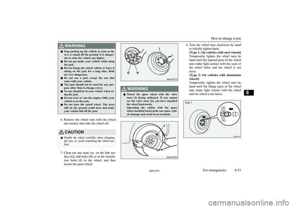
face (G), hub bolts (H) or in the installa- tion holes (I) in the wheel, and then
mount the spare wheel.
WARNINGl Mount the spare wheel with the valve
stem (J) facing outboard. If you cannot see the valve stem (J), you have installed the wheel backwards.
Operating the vehicle with the spare
wheel installed backwards can cause vehi-
cle damage and result in an accident.8. Turn the wheel nuts clockwise by hand
to initially tighten them.
[Type 1: On vehicles with steel wheels]
Temporarily tighten the wheel nuts by hand until the tapered parts of the wheel nuts make light contact with the seats of the wheel holes and the wheel is not
loose.
[Type 2: On vehicles with aluminium wheels]
Temporarily tighten the wheel nuts by
hand until the flange parts of the wheel nuts make light contact with the wheel
and the wheel is not loose.
How to change a tyre
8-21OKTE17E1For emergencies8 Type 1
Page 334 of 426
NOTElFlange nuts can be temporarily used on the
steel spare wheel as shown in the illustra- tion, but return to the original wheel and tyre
as soon as possible.CAUTIONl Never apply oil to either the wheel bolts or
the nuts, or they will tighten too much.NOTEl If all 4 aluminium wheels are changed to
steel wheels. e. g. when fitting winter tyres,
use tapered nuts.
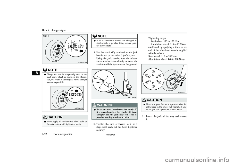
9. Put the notch (K) provided on the jack
handle end on the valve (L) of the jack.
Using the jack handle, turn the release valve anticlockwise slowly to lower thevehicle until the tyre touches the ground.
WARNINGl Be sure to open the release valve slowly. If
it is opened quickly, the vehicle will drop
abruptly and the jack may come out of
position, causing a serious accident.
10. Tighten the nuts crisscross in 2 or 3
steps until each nut has been tightened securely.
Tightening torqueSteel wheel: 137 to 157 N•m
Aluminium wheel: 118 to 137 N•m
(Achieved by applying a force at the
end of the wheel nut wrench supplied with the vehicle.
Steel wheel: 510 to 580 N•m
Aluminium wheel: 440 to 500 N•m)CAUTIONl Never use your foot or a pipe extension for
extra force in the wheel nut wrench. If you
do so, you will tighten the nut too much.
11. Lower the jack all the way and remove
it.
How to change a tyre
8-22OKTE17E1For emergencies8Type 2