tow MITSUBISHI LANCER 2005 User Guide
[x] Cancel search | Manufacturer: MITSUBISHI, Model Year: 2005, Model line: LANCER, Model: MITSUBISHI LANCER 2005Pages: 788, PDF Size: 45.98 MB
Page 214 of 788
TRAILING ARM ASSEMBLY
REAR SUSPENSION34-14
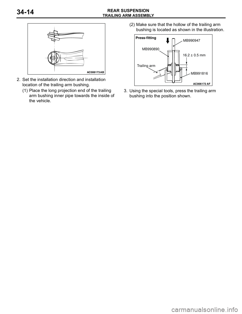
2. Set the installation direction and installation
location of the trailing arm bushing.
(1) Place the long projection end of the trailing
arm bushing inner pipe towards the inside of
the vehicle.(2) Make sure that the hollow of the trailing arm
bushing is located as shown in the illustration.
3. Using the special tools, press the trailing arm
bushing into the position shown.
AC006173 AB
AC006172AF
Press-fitting
MB990890
Trailing armMB990947
MB991816 16.2 ± 0.5 mm
Page 216 of 788
Page 232 of 788
Page 245 of 788
ON-VEHICLE SERVICE
POWER STEERING37-11
ON-VEHICLE SERVICE
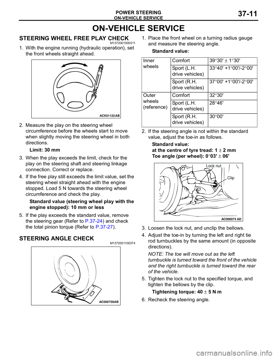
STEERING WHEEL FREE PLAY CHECKM1372001000311
1. With the engine running (hydraulic operation), set
the front wheels straight ahead.
2. Measure the play on the steering wheel
circumference before the wheels start to move
when slightly moving the steering wheel in both
directions.
Limit: 30 mm
3. When the play exceeds the limit, check for the
play on the steering shaft and steering linkage
connection. Correct or replace.
4. If the free play still exceeds the limit value, set the
steering wheel straight ahead with the engine
stopped. Load 5 N towards the steering wheel
circumference and check the play.
Standard value (steering wheel play with the
engine stopped): 10 mm or less
5. If the play exceeds the standard value, remove
the steering gear (Refer to P.37-24) and check
the total pinion torque (Refer to P.37-27).
STEERING ANGLE CHECKM1372001100374
1. Place the front wheel on a turning radius gauge
and measure the steering angle.
Standard value:
2. If the steering angle is not within the standard
value, adjust the toe-in as follows.
Standard value:
at the centre of tyre tread: 1 ± 2 mm
Toe angle (per wheel): 0°03' ± 06'
3. Loosen the lock nut, and unclip the bellows.
4. Adjust the toe-in by turning the left and right tie
rod turnbuckles by the same amount (in opposite
directions).
NOTE: The toe will move out as the left
turnbuckle is turned toward the front of the vehicle
and the right turnbuckle is turned toward the rear
of the vehicle.
5. Tighten the lock nut to the specified torque, and
tighten the bellows by the clip.
Tightening torque: 40 ± 5 N⋅m
6. Recheck the steering angle.
ACX01122
AB
AC000756AB
Inner
wheelsComfort 39°30' ± 1°30'
Sport (L.H.
drive vehicles)33°40' +1°00'/-2°00'
Sport (R.H.
drive vehicles)37°00' +1°00'/-2°00'
Outer
wheels
(reference)Comfort 32°30'
Sport (L.H.
drive vehicles)28°46'
Sport (R.H.
drive vehicles)30°00'
AC006074AD
Lock nut
Clip
Page 256 of 788
STEERING SHAFT
POWER STEERING37-22
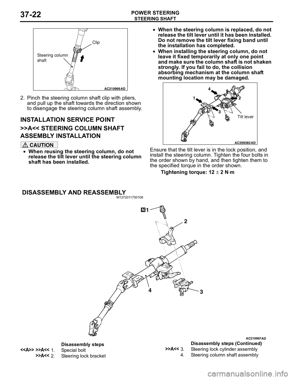
2. Pinch the steering column shaft clip with pliers,
and pull up the shaft towards the direction shown
to disengage the steering column shaft assembly.
INSTALLATION SERVICE POINT
>>A<< STEERING COLUMN SHAFT
ASSEMBLY INSTALLATION
CAUTION
•When reusing the steering column, do not
release the tilt lever until the steering column
shaft has been installed.•When the steering column is replaced, do not
release the tilt lever until it has been installed.
Do not remove the tilt lever fixing band until
the installation has completed.
•When installing the steering column, do not
leave it fixed temporarily at only one point
and make sure the column shaft is not shaken
strongly. If you fail to do, the collision
absorbing mechanism at the column shaft
mounting location may be damaged.
Ensure that the tilt lever is in the lock position, and
install the steering column. Tighten the four bolts in
the order shown by hand, and then tighten them to
the specified torque in the order shown.
Tightening torque: 12 ± 2 N⋅m
DISASSEMBLY AND REASSEMBLYM1372011700106
AC210969AD
Clip
Steering column
shaft
AC209383
AD
14
32
Tilt lever
AC210967AD
3 2 14
Disassembly steps
<> >>A<<1. Special bolt
>>A<<2. Steering lock bracket
>>A<<3. Steering lock cylinder assembly
4. Steering column shaft assemblyDisassembly steps (Continued)
Page 268 of 788
POWER STEERING GEAR BOX AND LINKAGE
POWER STEERING37-34
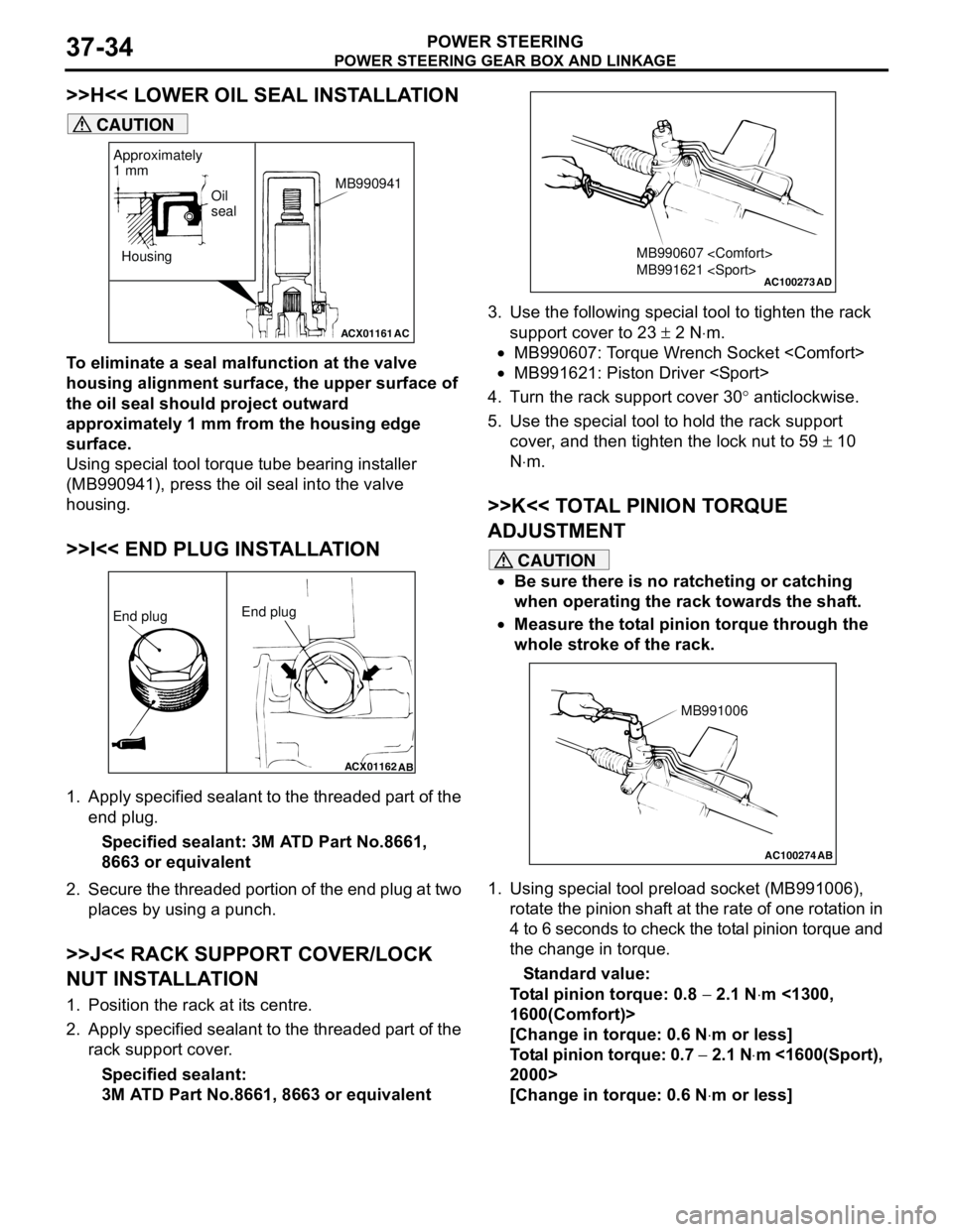
>>H<< LOWER OIL SEAL INSTALLATION
CAUTION
To eliminate a seal malfunction at the valve
housing alignment surface, the upper surface of
the oil seal should project outward
approximately 1 mm from the housing edge
surface.
Using special tool torque tube bearing installer
(MB990941), press the oil seal into the valve
housing.
>>I<< END PLUG INSTALLATION
1. Apply specified sealant to the threaded part of the
end plug.
Specified sealant: 3M ATD Part No.8661,
8663 or equivalent
2. Secure the threaded portion of the end plug at two
places by using a punch.
>>J<< RACK SUPPORT COVER/LOCK
NUT INSTALLATION
1. Position the rack at its centre.
2. Apply specified sealant to the threaded part of the
rack support cover.
Specified sealant:
3M ATD Part No.8661, 8663 or equivalent3. Use the following special tool to tighten the rack
support cover to 23 ± 2 N⋅m.
•MB990607: Torque Wrench Socket
•MB991621: Piston Driver
4. Turn the rack support cover 30° anticlockwise.
5. Use the special tool to hold the rack support
cover, and then tighten the lock nut to 59 ± 10
N⋅m.
>>K<< TOTAL PINION TORQUE
ADJUSTMENT
CAUTION
•Be sure there is no ratcheting or catching
when operating the rack towards the shaft.
•Measure the total pinion torque through the
whole stroke of the rack.
1. Using special tool preload socket (MB991006),
rotate the pinion shaft at the rate of one rotation in
4 to 6 seconds to check the total pinion torque and
the change in torque.
Standard value:
Total pinion torque: 0.8 − 2.1 N⋅m <1300,
1600(Comfort)>
[Change in torque: 0.6 N⋅m or less]
Total pinion torque: 0.7 − 2.1 N⋅m <1600(Sport),
2000>
[Change in torque: 0.6 N⋅m or less]
ACX01161
Housing
AC
Oil
seal
Approximately
1 mm
MB990941
ACX01162
AB
End plugEnd plug
AC100273
MB990607
MB991621
AD
AC100274 AB
MB991006
Page 279 of 788
42-1
GROUP 42
BODY
CONTENTS
HOOD . . . . . . . . . . . . . . . . . . . . .
42-3
ON-VEHICLE SERVICE. . . . . . . . .
42-3
ADJUSTMENT OF CLEARANCE
AROUND HOOD . . . . . . . . . . . . . . . . . . 42-3
ADJUSTMENT OF ALIGNMENT OF
HOOD STEPPED PORTION AND
HOOD STRIKER . . . . . . . . . . . . . . . . . . 42-3
ADJUSTMENT OF HOOD HEIGHT . . . 42-3
HOOD . . . . . . . . . . . . . . . . . . . . . . .42-4
REMOVAL AND INSTALLATION . . . . . 42-4
FENDER . . . . . . . . . . . . . . . . . . .42-5
SPECIAL TOOL . . . . . . . . . . . . . . .
42-5
FENDER . . . . . . . . . . . . . . . . . . . . .42-6
REMOVAL AND INSTALLATION . . . . . 42-6
FUEL FILLER LID . . . . . . . . . . .42-8
REMOVAL AND INSTALLATION .
42-8
STRUT TOWER BAR . . . . . . . .42-9
REMOVAL AND INSTALLATION .
42-9
WINDOW GLASS . . . . . . . . . . . 42-9
ADHESIVE . . . . . . . . . . . . . . . . . . .
42-9
SPECIAL TOOLS . . . . . . . . . . . . . .42-9
WINDOW REPAIR . . . . . . . . . . . . .42-10
WINDSHIELD . . . . . . . . . . . . . . . . .42-12
REMOVAL AND INSTALLATION . . . . . . 42-12
REAR WINDOW GLASS . . . . . . . .42-16
REMOVAL AND INSTALLATION . . . . . . 42-16
QUARTER WINDOW GLASS . . . .42-19
REMOVAL AND INSTALLATION . . . . . . 42-19
TAILGATE WINDOW GLASS . . . .42-22
REMOVAL AND INSTALLATION . . . . . . 42-22
DOOR . . . . . . . . . . . . . . . . . . . . 42-25
SERVICE SPECIFICATIONS . . . . .
42-25
SEALANT . . . . . . . . . . . . . . . . . . . .42-25
SPECIAL TOOLS . . . . . . . . . . . . . .42-25
Continued on next page
Page 287 of 788
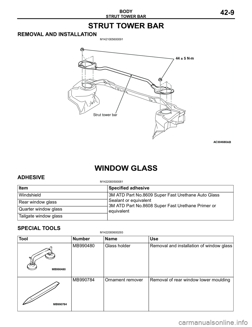
STRUT TOWER BAR
BODY42-9
STRUT TOWER BAR
REMOVAL AND INSTALLATIONM1421005600091
WINDOW GLASS
ADHESIVEM1422000500081
SPECIAL TOOLSM1422000600293
AC304680AB
Strut tower bar44 ± 5 N·m
Item Specified adhesive
Windshield 3M ATD Part No.8609 Super Fast Urethane Auto Glass
Sealant or equivalent
3M ATD Part No.8608 Super Fast Urethane Primer or
equivalent Rear window glass
Quarter window glass
Tailgate window glass
Tool Number Name Use
MB990480 Glass holder Removal and installation of window glass
MB990784 Ornament remover Removal of rear window lower moulding
MB990480
MB990784
Page 305 of 788
DOOR
BODY42-27
ON-VEHICLE SERVICE
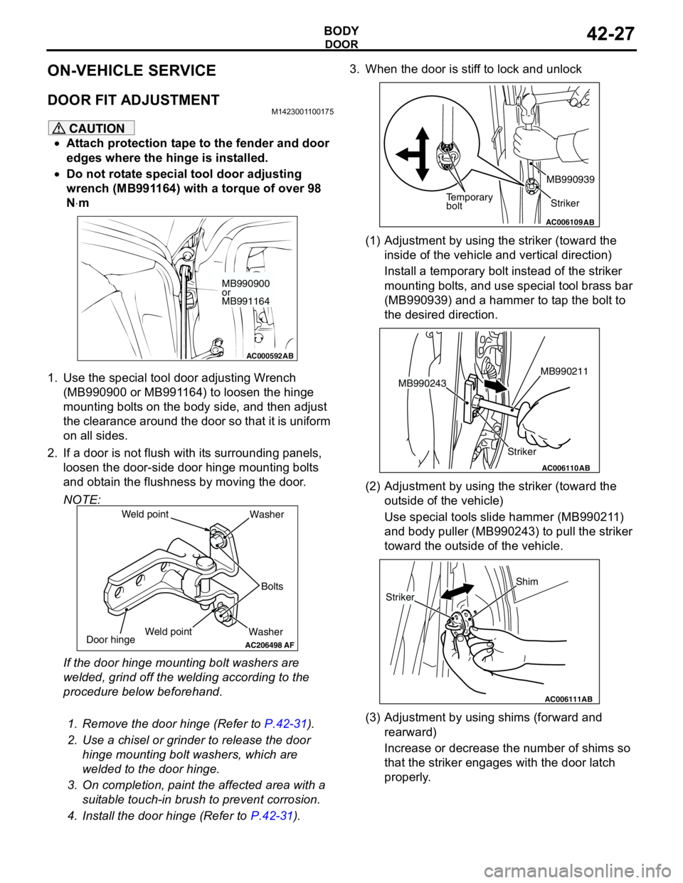
DOOR FIT ADJUSTMENTM1423001100175
CAUTION
•Attach protection tape to the fender and door
edges where the hinge is installed.
•Do not rotate special tool door adjusting
wrench (MB991164) with a torque of over 98
N⋅m
1. Use the special tool door adjusting Wrench
(MB990900 or MB991164) to loosen the hinge
mounting bolts on the body side, and then adjust
the clearance around the door so that it is uniform
on all sides.
2. If a door is not flush with its surrounding panels,
loosen the door-side door hinge mounting bolts
and obtain the flushness by moving the door.
NOTE:
If the door hinge mounting bolt washers are
welded, grind off the welding according to the
procedure below beforehand.
.
1. Remove the door hinge (Refer to P.42-31).
2. Use a chisel or grinder to release the door
hinge mounting bolt washers, which are
welded to the door hinge.
3. On completion, paint the affected area with a
suitable touch-in brush to prevent corrosion.
4. Install the door hinge (Refer to P.42-31).3. When the door is stiff to lock and unlock
(1) Adjustment by using the striker (toward the
inside of the vehicle and vertical direction)
Install a temporary bolt instead of the striker
mounting bolts, and use special tool brass bar
(MB990939) and a hammer to tap the bolt to
the desired direction.
(2) Adjustment by using the striker (toward the
outside of the vehicle)
Use special tools slide hammer (MB990211)
and body puller (MB990243) to pull the striker
toward the outside of the vehicle.
(3) Adjustment by using shims (forward and
rearward)
Increase or decrease the number of shims so
that the striker engages with the door latch
properly.
AC000592
MB990900
or
MB991164
AB
AC206498
WasherBolts Washer
Door hinge
AF
Weld point Weld point
AC006109AB
Temporary
boltStriker MB990939
AC006110
StrikerMB990211
MB990243
AB
AC006111AB
Shim
Striker
Page 337 of 788
