Intake MITSUBISHI LANCER 2005 Owner's Manual
[x] Cancel search | Manufacturer: MITSUBISHI, Model Year: 2005, Model line: LANCER, Model: MITSUBISHI LANCER 2005Pages: 788, PDF Size: 45.98 MB
Page 341 of 788
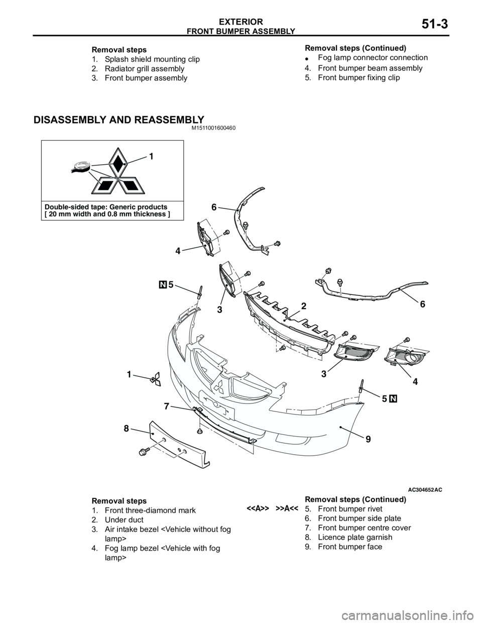
FRONT BUMPER ASSEMBLY
EXTERIOR51-3
DISASSEMBLY AND REASSEMBLYM1511001600460
Removal steps
1. Splash shield mounting clip
2. Radiator grill assembly
3. Front bumper assembly•Fog lamp connector connection
4. Front bumper beam assembly
5. Front bumper fixing clip Removal steps (Continued)
AC304652AC
Double-sided tape: Generic products
[ 20 mm width and 0.8 mm thickness ]
1
1
8
7
9
6
6
5
5
3
4
34
N
N
2
Removal steps
1. Front three-diamond mark
2. Under duct
3. Air intake bezel
4. Fog lamp bezel
6. Front bumper side plate
7. Front bumper centre cover
8. Licence plate garnish
9. Front bumper face Removal steps (Continued)
Page 551 of 788

TROUBLESHOOTING
HEATER, AIR CONDITIONER AND VENTILATION55-67
CHECK AT ECU TERMINAL
12
345
678
9 10111213141516
AC300861AC
Terminal No. Check item Checking requirement Normal condition
1 Rear defogger switch Defogger switch: ON 0 V
Defogger switch: OFF System voltage
2 Inside/outside air selection
damper motor (outside air)When the damper is moved to
the inside air recirculation
position0 V
When the damper is moved to
the outside air inside air intake
positionSystem voltage
3 Inside/outside air selection
damper motor (inside air)When the damper is moved to
the inside air recirculation
positionSystem voltage
When the damper is moved to
the outside air inside air intake
position0 V
4 Output to the engine-A/T-ECU
(A/C1)A/C stopped 0 V
•A/C switch: ON
•Blower switch: ONSystem voltage
5 Output to the engine-A/T-ECU
(A/C2)When the A/C is under low load System voltage
When the A/C is under high
load0 V
6 Power supply to the A/C
illuminationLighting switch: ON System voltage
7---
8 Blower switch (lo) blower switch: lo System voltage
9---
10 Power supply to the ignition
switch (IG2)Ignition switch: ON System voltage
11 Earth to the A/C illumination Always 0 V
12 Earth Always 0 V
13 Air thermo sensor (outlet side) Sensor probe temperature 25°C
(1.5k ohm)2.2 V
14, 15 - - -
16 Earth to the air thermo sensor Always 0 V
Page 552 of 788

TROUBLESHOOTING
HEATER, AIR CONDITIONER AND VENTILATION55-68
CHECK AT ECU TERMINAL
21
78
6 534
11
10912
AC304990
AB
Terminal No. Check item Checking requirement Normal condition
1 Output to the engine-A/T-ECU
(A/C1)A/C stopped 0 V
•A/C switch: ON
•Blower switch: ONSystem voltage
2 Output to the engine-A/T-ECU
(A/C2)When the A/C is under low load System voltage
When the A/C is under high
load0 V
3 Earth Always 0 V
4 Earth to the air thermo sensor Always 0 V
5 Power supply to the A/C
illuminationLighting switch: ON System voltage
6 Air thermo sensor (outlet side) Sensor probe temperature 25°C
(1.5k ohm)2.2 V
7 Power supply to the ignition
switch (IG2)Ignition switch: ON System voltage
8 Blower switch (lo) blower switch: lo System voltage
9 Rear defogger switch Defogger switch: ON 0 V
Defogger switch: OFF System voltage
10 Inside/outside air selection
damper motor (outside air)When the damper is moved to
the inside air recirculation
position0 V
When the damper is moved to
the outside air inside air intake
positionSystem voltage
11 Inside/outside air selection
damper motor (inside air)When the damper is moved to
the inside air recirculation
positionSystem voltage
When the damper is moved to
the outside air inside air intake
position0 V
12 Earth to the A/C illumination Always 0 V
Page 565 of 788
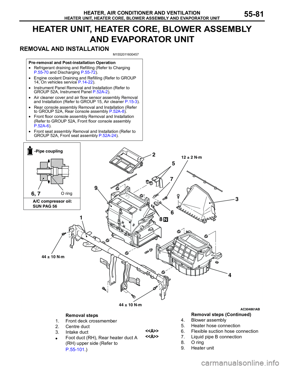
HEATER UNIT, HEATER CORE, BLOWER ASSEMBLY AND EVAPORATOR UNIT
HEATER, AIR CONDITIONER AND VENTILATION55-81
HEATER UNIT, HEATER CORE, BLOWER ASSEMBLY
AND EVAPORATOR UNIT
REMOVAL AND INSTALLATION
M1552011600457
Pre-removal and Post-installation Operation
•Refrigerant draining and Refilling (Refer to Charging
P.55-70 and Discharging P.55-72).
•Engine coolant Draining and Refilling (Refer to GROUP
14, On vehicles service P.14-22).
•Instrument Panel Removal and Installation (Refer to
GROUP 52A, Instrument Panel P.52A-2).
•Air cleaner cover and air flow sensor assembly Removal
and Installation (Refer to GROUP 15, Air cleaner P.15-3).
•Rear console assembly Removal and Installation (Refer
to GROUP 52A, Rear console assembly P.52A-8).
•Front floor console assembly Removal and Installation
(Refer to GROUP 52A, Front floor console assembly
P.52A-6).
•Front seat assembly Removal and Installation (Refer to
GROUP 52A, Front seat assembly P.52A-24).
AC304861
1
2
3
4 5
6
7
8
N
9
AB
12 ± 2 N·m
6, 7O ring -Pipe coupling
A/C compressor oil:
SUN PAG 56
44 ± 10 N·m
44 ± 10 N·m
Removal steps
1. Front deck crossmember
2. Centre duct
3. Intake duct
•Foot duct (RH), Rear heater duct A
(RH) upper side (Refer to
P.55-101.)4. Blower assembly
5. Heater hose connection
<>6. Flexible suction hose connection
<>7. Liquid pipe B connection
8. O ring
9. Heater unitRemoval steps (Continued)
Page 592 of 788
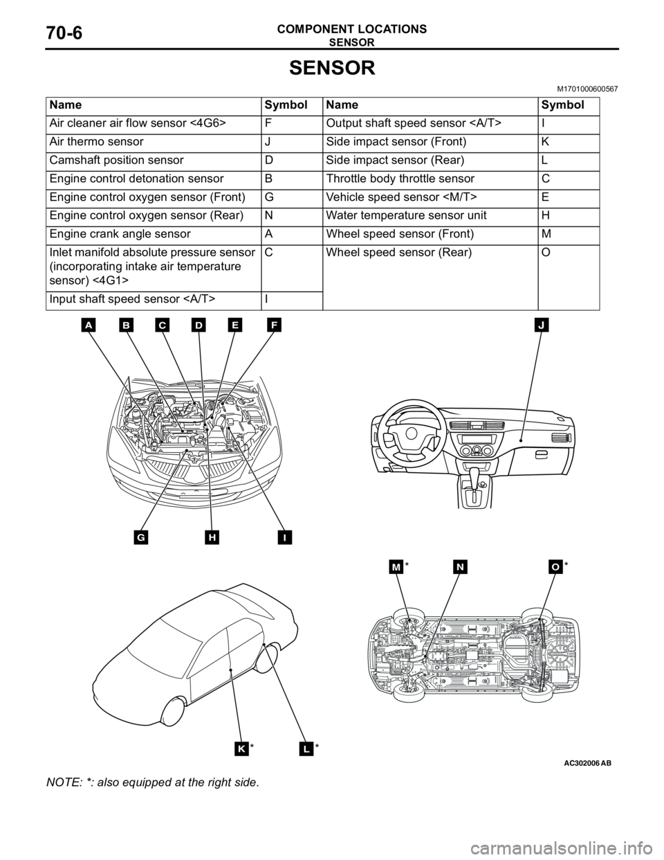
SENSOR
COMPONENT LOCATIONS70-6
SENSOR
M1701000600567
NOTE: *: also equipped at the right side.Name Symbol Name Symbol
Air cleaner air flow sensor <4G6> F Output shaft speed sensor I
Air thermo sensor J Side impact sensor (Front) K
Camshaft position sensor D Side impact sensor (Rear) L
Engine control detonation sensor B Throttle body throttle sensor C
Engine control oxygen sensor (Front) G Vehicle speed sensor
Engine control oxygen sensor (Rear) N Water temperature sensor unit H
Engine crank angle sensor A Wheel speed sensor (Front) M
Inlet manifold absolute pressure sensor
(incorporating intake air temperature
sensor) <4G1>C Wheel speed sensor (Rear) O
Input shaft speed sensor I
AC302006AB
BDCFEA
GHI
J
KL
MNO
*
***
Page 593 of 788
SENSOR
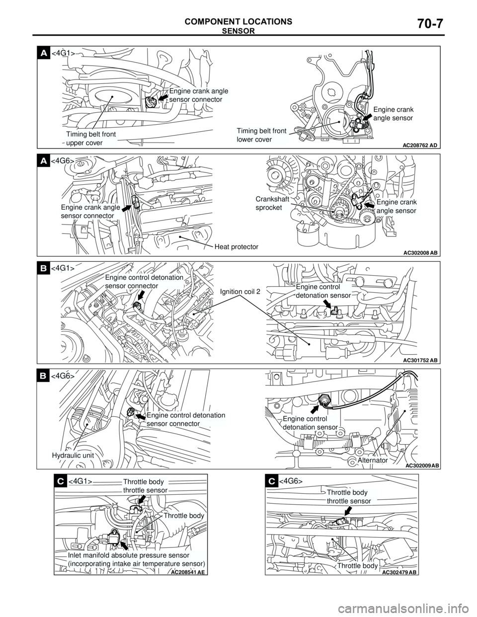
COMPONENT LOCATIONS70-7
AC208762
A
AD
Timing belt front
upper coverTiming belt front
lower coverEngine crank
angle sensor
<4G1>
Engine crank angle
sensor connector
AC302008
A<4G6>
ABHeat protector
Crankshaft
sprocket
Engine crank angle
sensor connectorEngine crank
angle sensor
AC301752
B
AB
Ignition coil 2
<4G1>
Engine control detonation
sensor connector
Engine control
detonation sensor
AC302009
B
AB
Hydraulic unit
<4G6>
Alternator
Engine control detonation
sensor connectorEngine control
detonation sensor
AC208541
C
AE
<4G1>
Throttle body
Throttle body
throttle sensor
Inlet manifold absolute pressure sensor
(incorporating intake air temperature sensor)
AC302479
AB
C
Throttle body
<4G6>
Throttle body
throttle sensor
Page 598 of 788
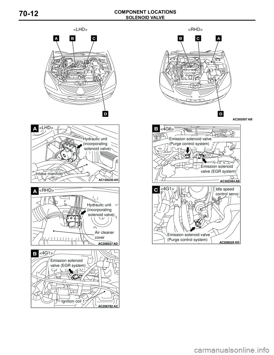
SOLENOID VALVE
COMPONENT LOCATIONS70-12
AC302007
AB
AB
ABC
D
C
D
AC100230
A
AH
Hydraulic unit
(incorporating
solenoid valve)
Intake manifold
AC208527
A
AD
Hydraulic unit
(incorporating
solenoid valve)
Air cleaner
cover
AC206782
<4G1>B
AC
Ignition coil 1
Emission solenoid
valve (EGR system)
AC302484
B
AB
<4G6>
Emission solenoid
valve (EGR system)
Emission solenoid valve
(Purge control system)
AC208529AD
C<4G1>Idle speed
control servo
Emission solenoid valve
(Purge control system)
Page 659 of 788
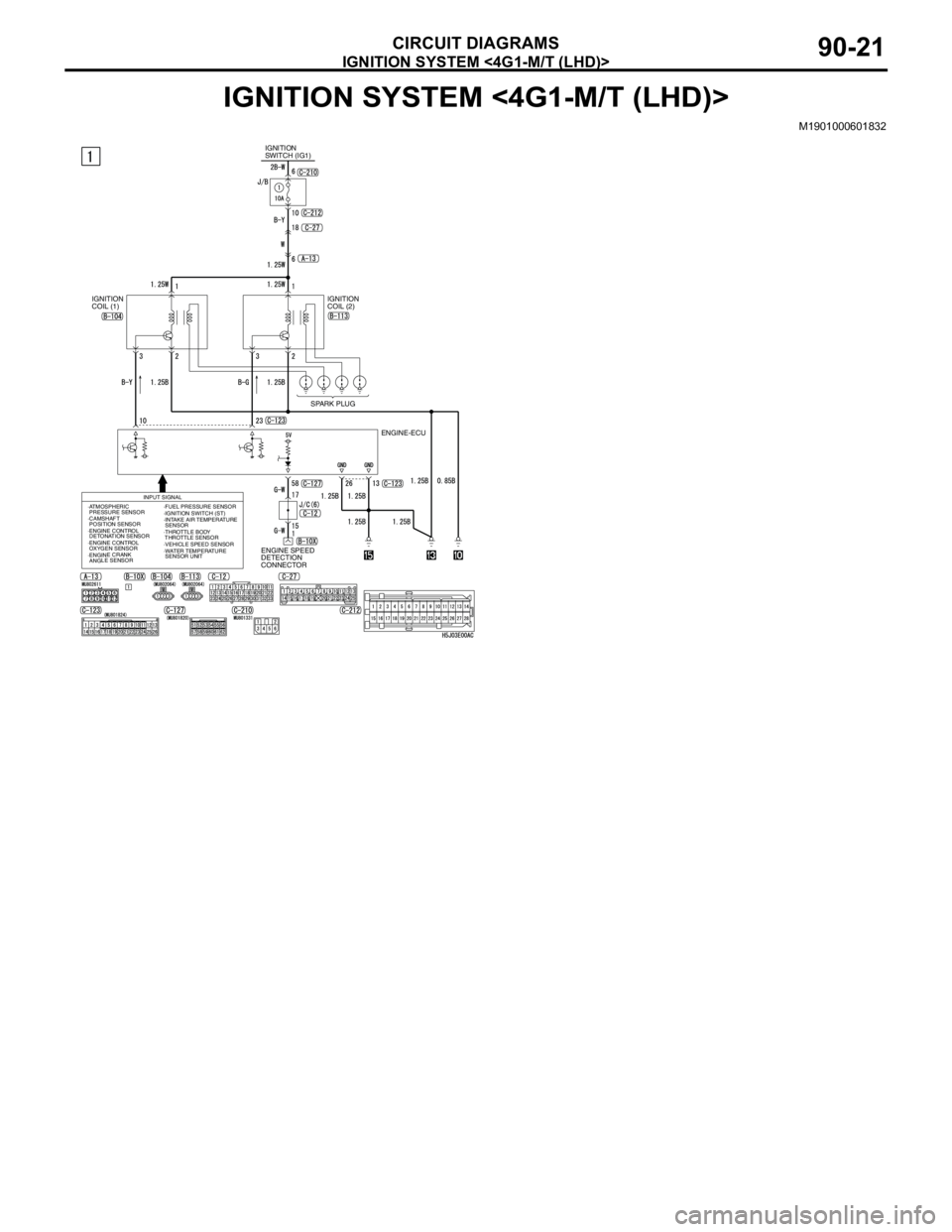
IGNITION SYSTEM <4G1-M/T (LHD)>
CIRCUIT DIAGRAMS90-21
IGNITION SYSTEM <4G1-M/T (LHD)>
M1901000601832
IGNITION
SWITCH (IG1)
IGNITION
COIL (1)IGNITION
COIL (2)
SPARK PLUG
ENGINE-ECU
ENGINE SPEED
DETECTION
CONNECTOR
INPUT SIGNAL
·ATMOSPHERIC
PRESSURE SENSOR
·CAMSHAFT
POSITION SENSOR
·ENGINE CRANK
ANGLE SENSOR·WATER TEMPERATURE
SENSOR UNIT ·ENGINE CONTROL
DETONATION SENSOR·FUEL PRESSURE SENSOR
·IGNITION SWITCH (ST)
·INTAKE AIR TEMPERATURE
SENSOR
·ENGINE CONTROL
OXYGEN SENSOR·VEHICLE SPEED SENSOR ·THROTTLE BODY
THROTTLE SENSOR
Page 660 of 788
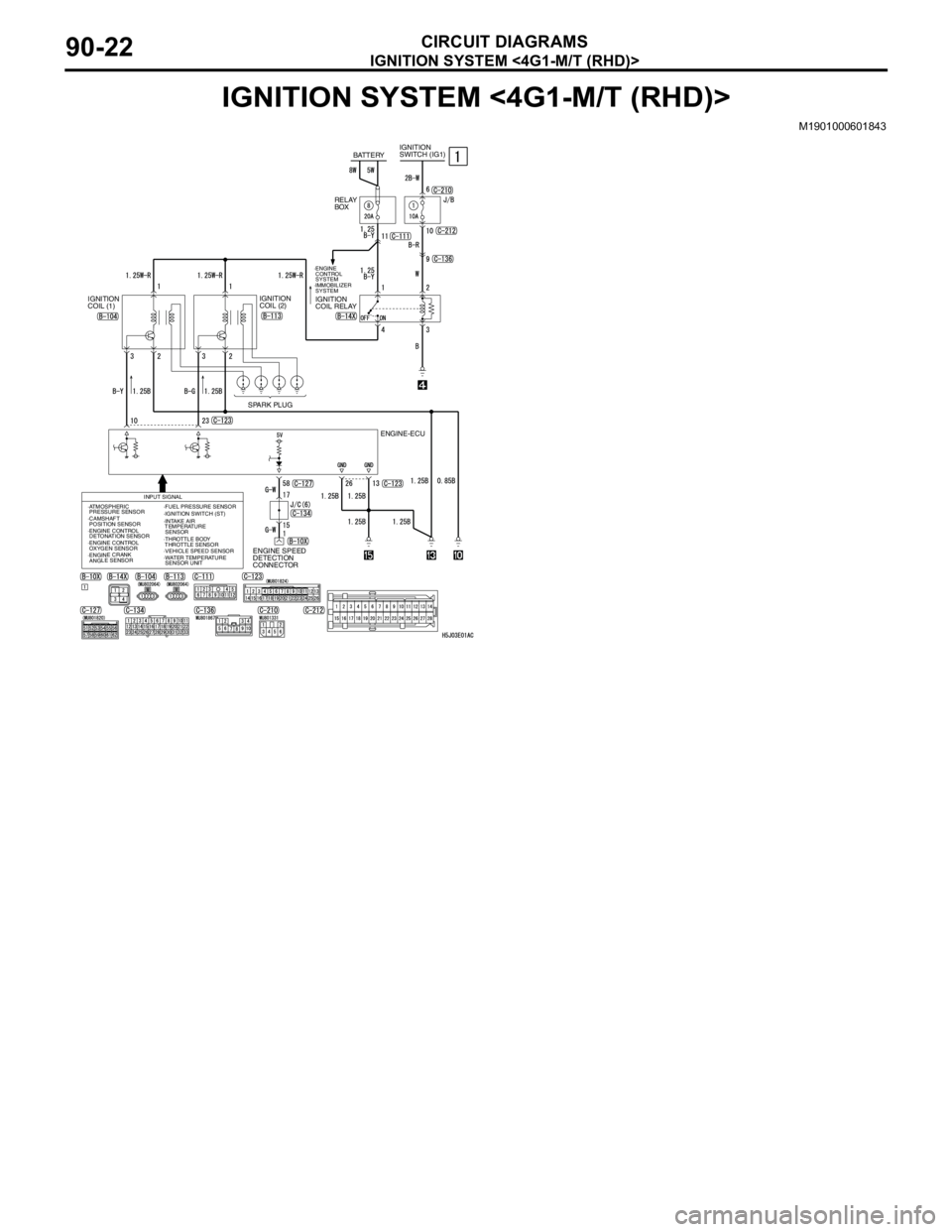
IGNITION SYSTEM <4G1-M/T (RHD)>
CIRCUIT DIAGRAMS90-22
IGNITION SYSTEM <4G1-M/T (RHD)>
M1901000601843
IGNITION
SWITCH (IG1)
IGNITION
COIL (1)IGNITION
COIL (2)
SPARK PLUG
ENGINE-ECU
ENGINE SPEED
DETECTION
CONNECTOR
INPUT SIGNAL
BATTERY
IGNITION
COIL RELAYRELAY
BOX
·ENGINE
CONTROL
SYSTEM
·IMMOBILIZER
SYSTEM
·ATMOSPHERIC
PRESSURE SENSOR
·CAMSHAFT
POSITION SENSOR
·ENGINE CRANK
ANGLE SENSOR·WATER TEMPERATURE
SENSOR UNIT ·ENGINE CONTROL
DETONATION SENSOR·FUEL PRESSURE SENSOR
·IGNITION SWITCH (ST)
·INTAKE AIR
TEMPERATURE
SENSOR
·ENGINE CONTROL
OXYGEN SENSOR
·VEHICLE SPEED SENSOR ·THROTTLE BODY
THROTTLE SENSOR
Page 661 of 788
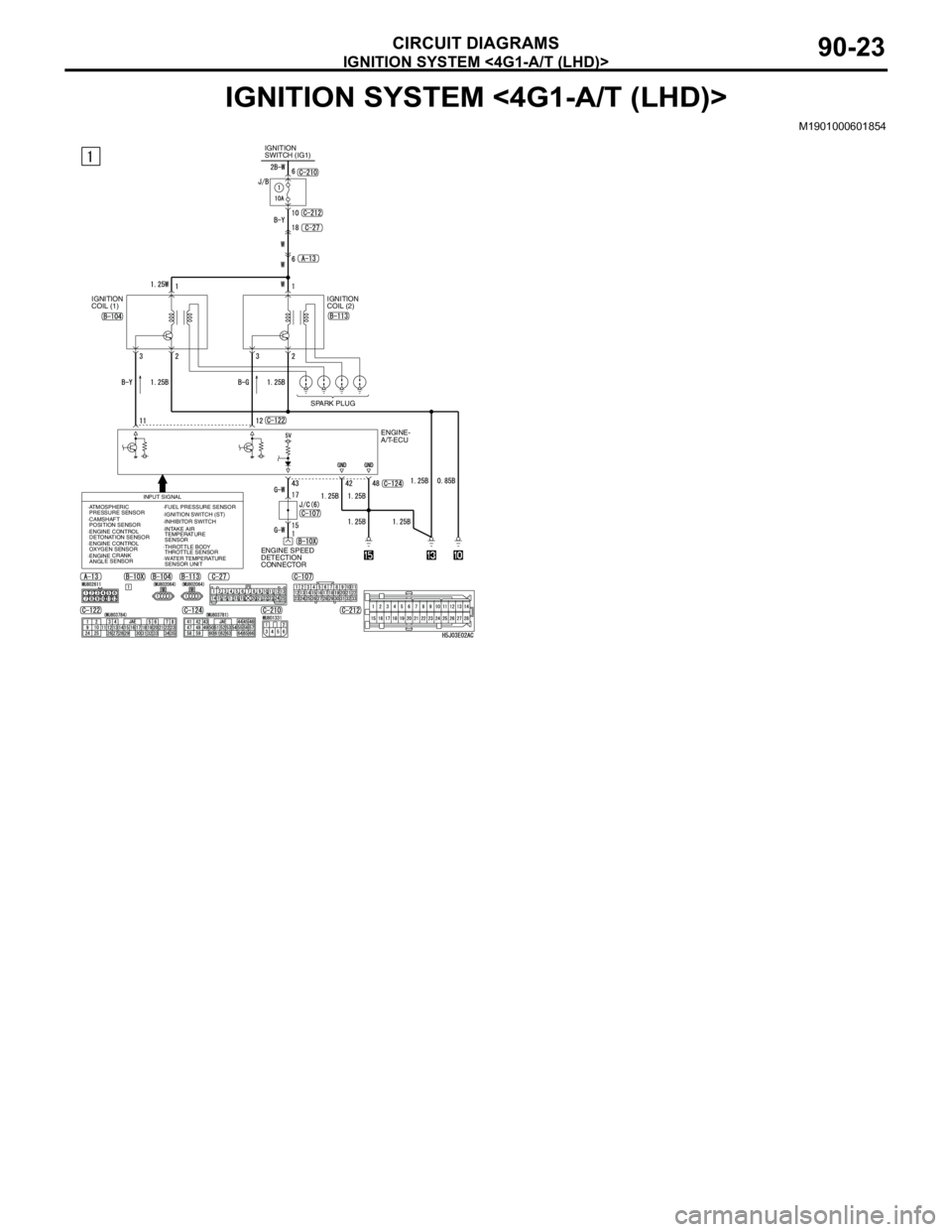
IGNITION SYSTEM <4G1-A/T (LHD)>
CIRCUIT DIAGRAMS90-23
IGNITION SYSTEM <4G1-A/T (LHD)>
M1901000601854
IGNITION
SWITCH (IG1)
IGNITION
COIL (1)IGNITION
COIL (2)
SPARK PLUG
ENGINE-
A/T-ECU
ENGINE SPEED
DETECTION
CONNECTOR
INPUT SIGNAL
·ATMOSPHERIC
PRESSURE SENSOR
·CAMSHAFT
POSITION SENSOR·FUEL PRESSURE SENSOR
·IGNITION SWITCH (ST)
·INTAKE AIR
TEMPERATURE
SENSOR ·INHIBITOR SWITCH
·ENGINE CRANK
ANGLE SENSOR·WATER TEMPERATURE
SENSOR UNIT ·ENGINE CONTROL
DETONATION SENSOR
·ENGINE CONTROL
OXYGEN SENSOR·THROTTLE BODY
THROTTLE SENSOR