warning MITSUBISHI LANCER 2005 Owner's Manual
[x] Cancel search | Manufacturer: MITSUBISHI, Model Year: 2005, Model line: LANCER, Model: MITSUBISHI LANCER 2005Pages: 788, PDF Size: 45.98 MB
Page 333 of 788
KEYLESS ENTRY SYSTEM
BODY42-55
NOTE: If any operation is not done for at least three
minutes after the ETACS-ECU has entered the
customize mode, the hazard answerback customize
mode will be canceled automatically.
(MB991824) to the diagnosis connector>
1. Enter the hazard answerback customize mode by
performing one of the following steps. If the
ETACS-ECU enters the customize mode, its
buzzer will sound once.
(1) Turn the ignition switch to “LOCK”(OFF)
position.
(2) Turn off the hazard warning lamp switch.
CAUTION
Before connecting or disconnecting the V. C. I.,
turn the ignition switch to the "LOCK" (OFF)
position.
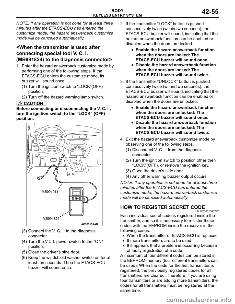
(3) Connect the V. C. I. to the diagnosis
connector.
(4) Turn the V.C.I. power switch to the "ON"
position.
(5) Close the driver's side door.
(6) Keep the windshield washer switch on for at
least ten seconds. Then the ETACS-ECU
buzzer will sound once.2. If the transmitter “LOCK” button is pushed
consecutively twice (within two seconds), the
ETACS-ECU buzzer will sound, indicating that the
hazard answerback function can be enabled or
disabled when the doors are locked.
•Enable the hazard answerback function
when the doors are locked: The
ETACS-ECU buzzer will sound once.
•Disable the hazard answerback function
when the doors are locked: The
ETACS-ECU buzzer will sound twice.
3. If the transmitter “UNLOCK” button is pushed
consecutively twice (within two seconds), the
ETACS-ECU buzzer will sound, indicating that the
hazard answerback function can be enabled or
disabled when the doors are unlocked.
•Enable the hazard answerback function
when the doors are unlocked: The
ETACS-ECU buzzer will sound once.
•Disable the hazard answerback function
when the doors are unlocked: The
ETACS-ECU buzzer will sound twice.
4. Exit the hazard answerback customize mode by
observing one of the following steps.
(1) Disconnect V. C. I. from the diagnosis
connector.
(2) Turn the ignition switch to position other then
“LOCK”(OFF), or remove the ignition key.
(3) Open the driver's side door.
(4) Any other warning buzzer output occurs.
NOTE: If any operation is not done for at least three
minutes after the ETACS-ECU has entered the
customize mode, the hazard answerback customize
mode will be canceled automatically.
HOW TO REGISTER SECRET CODEM1428001000292
Each individual secret code is registered inside the
transmitter, and so it is necessary to resister these
codes with the EEPROM inside the receiver in the
following cases.
•When the transmitter or ETACS-ECU is replaced
•If more transmitters are to be used
•If it appears that a problem is occurring because
of faulty registration of a code.
A maximum of four different codes can be stored in
the EEPROM memory (four different transmitters can
be used). When the code for the first transmitter is
registered, the previously registered codes for all
transmitters are cleared. Therefore, if you are using
four transmitters or are adding more transmitters, the
codes for all transmitters must be registered at the
same time.
AC305153AB
MB991911
MB991824
16-Pin
Page 334 of 788

KEYLESS ENTRY SYSTEM
BODY42-56
WHEN THE SPECIAL TOOL DIAGNOSIS
CODE CHECK HARNESS (MB991529) IS
USED
1. Check that the doors lock normally when the key
is used.
2. Insert the ignition key.
CAUTION
Before connecting or disconnecting the earth,
turn the ignition switch to the "LOCK" (OFF)
position.
3. Connect the diagnosis connector to the special
tool diagnosis code check harness (MB991529).
NOTE: This will connect terminal (1) of the
diagnosis connector to earth, and the system will
be in secret code registration standby mode.
4. Press the hazard warning lamp switch six times
within 10 seconds.
NOTE: Once the process is completed six times,
then it will operate with all doors and tailgate lock
and unlock operations once and then go to the
save mode.
NOTE: The hazard warning lamp switch is turned
on and off alternately whenever it is pushed.
5. Press the transmitter switch, and then press it two
times within 10 seconds of the first press. This will
register the code.
6. Once the program is saved, it will operate once
with the all doors and tailgate lock and unlock
operations. 7. If you are using two or more transmitters or have
added a second transmitter, the same registration
procedure should be carried out within one minute
after registering the code for the first transmitter.
8. Registration mode will be cancelled under the
following conditions:
•When the secret code for four transmitters has
been registered;
•When one minute has passed after registration
mode started;
•When the diagnosis connector is disconnected
from earth;
•When the key is removed from the key cylinder;
9. After the registration is completed, remove the
ignition key and close all the doors, and then
check that the keyless entry system operates
normally.
WHEN THE MUT-II IS USED
1. Check that the doors lock normally when the key
is used.
2. Insert the ignition key.
CAUTION
Before connecting or disconnecting the MUT-II,
turn the ignition switch to the "LOCK" (OFF)
position.
3. Connect the MUT-II to the diagnosis connector.
4. Press the hazard warning switch six times within
10 seconds.
AC305133AB
Diagnosis
connector
MB991529Steering shaft
ACX00571
Ground connected
Within 10 seconds
Hazard
warning
switchON
OFF12345
6
AGAC304777
Steering shaft
ACMB991502
16-Pin
ACX00571
MUT-II connected
Within 10 seconds
Hazard
warning
switchON
OFF12345
6
AB
Page 335 of 788
KEYLESS ENTRY SYSTEM
BODY42-57
NOTE: Once the process is completed six times,
then it will operate with all doors and tailgate lock
and unlock operations once and then go to the
save mode.
NOTE: The hazard warning lamp switch is turned
on and off alternately whenever it is pushed.
5. Press the transmitter switch, and then press it two
times within 10 seconds of the first press. This will
register the code.
6. Once the program is saved, it will operate once
with the all doors and tailgate lock and unlock
operations.
7. If you are using two or more transmitters or have
added a second transmitter, the same registration
procedure should be carried out within one minute
after registering the code for the first transmitter.
8. Registration mode will be cancelled under the
following conditions:
•When the secret code for four transmitters has
been registered;
•When one minute has passed after registration
mode started;
•When the MUT-II is disconnected from the
diagnosis connector;
•When the key is removed from the key cylinder;
9. After the registration is completed, remove the
ignition key and close all the doors, and then
check that the keyless entry system operates
normally.
WHEN THE SPECIAL TOOL V. C. I.
(MB991824) IS USED
1. Check that the doors lock normally when the key
is used.
2. Insert the ignition key.
CAUTION
Before connecting or disconnecting the V. C. I.,
turn the ignition switch to the "LOCK" (OFF)
position.
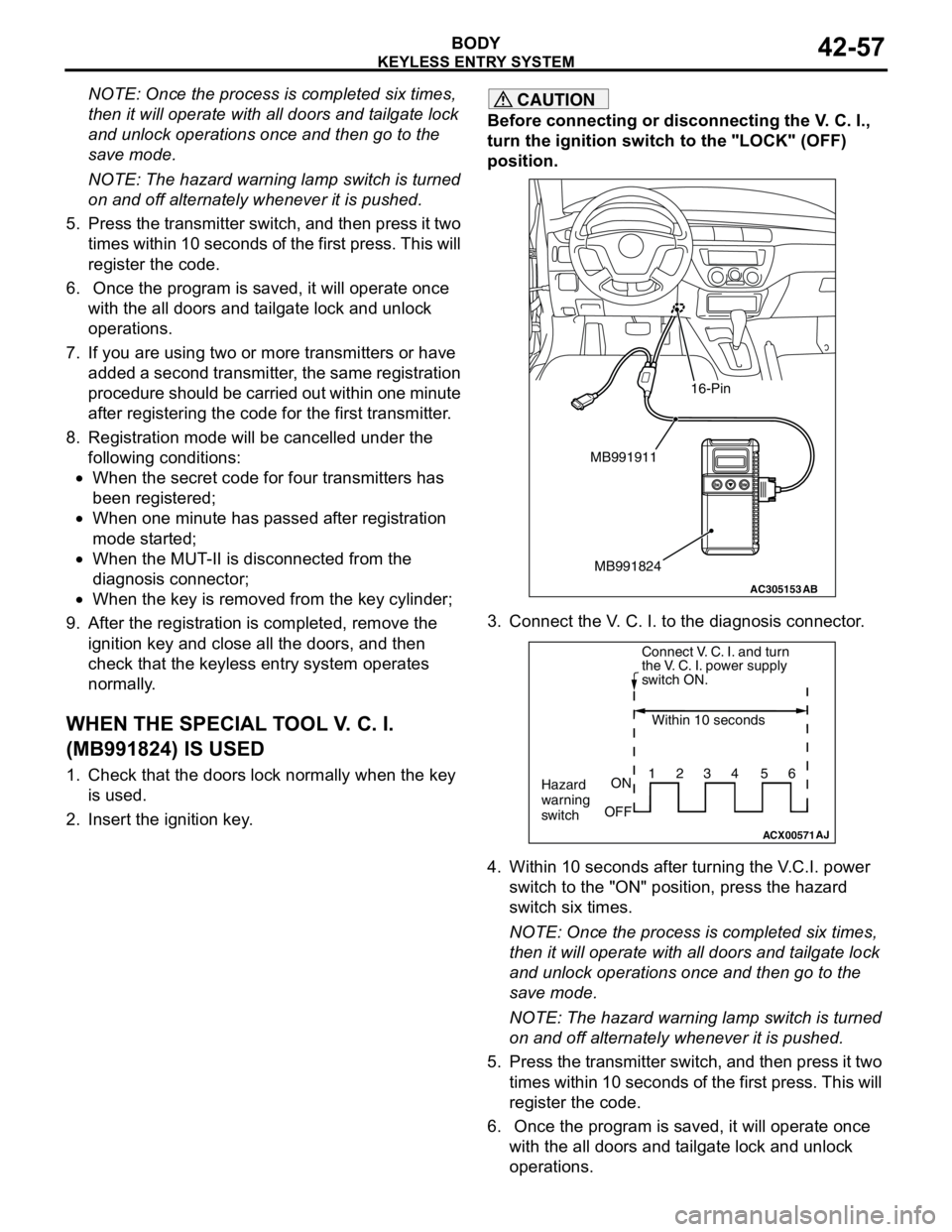
3. Connect the V. C. I. to the diagnosis connector.
4. Within 10 seconds after turning the V.C.I. power
switch to the "ON" position, press the hazard
switch six times.
NOTE: Once the process is completed six times,
then it will operate with all doors and tailgate lock
and unlock operations once and then go to the
save mode.
NOTE: The hazard warning lamp switch is turned
on and off alternately whenever it is pushed.
5. Press the transmitter switch, and then press it two
times within 10 seconds of the first press. This will
register the code.
6. Once the program is saved, it will operate once
with the all doors and tailgate lock and unlock
operations.
AC305153AB
MB991911
MB991824
16-Pin
ACX00571
Connect V. C. I. and turn
the V. C. I. power supply
switch ON.
Within 10 seconds
Hazard
warning
switchON
OFF1234 56
AJ
Page 389 of 788
54A-1
GROUP 54A
CHASSIS
ELECTRICAL
CONTENTS
BATTERY. . . . . . . . . . . . . . . . . .
54A-4
SERVICE SPECIFICATIONS. . . . .
54A-4
ON-VEHICLE SERVICE. . . . . . . . .54A-4
FLUID LEVEL AND SPECIFIC
GRAVITY CHECK . . . . . . . . . . . . . . . . . 54A-4
CHARGING . . . . . . . . . . . . . . . . . . . . . . 54A-4
BATTERY TEST . . . . . . . . . . . . . . . . . . 54A-5
IGNITION SWITCH* . . . . . . . . . .54A-6
GENERAL INFORMATION . . . . . .
54A-6
SPECIAL TOOLS. . . . . . . . . . . . . .54A-8
TROUBLESHOOTING . . . . . . . . . .54A-9
IGNITION KEY REMINDER BUZZER AND
DOOR LOCK PREVENTION FUNCTION
TROUBLESHOOTING . . . . . . . . . . . . . . 54A-9
IMMOBILIZER SYSTEM
TROUBLESHOOTING . . . . . . . . . .
54A-9
DIAGNOSIS CODE CHART . . . . . . . . . . 54A-9
DIAGNOSTIC TROUBLE CODE
PROCEDURES . . . . . . . . . . . . . . . .
54A-10
SYMPTOM CHART. . . . . . . . . . . . .54A-11
SYMPTOM PROCEDURES . . . . . .54A-12
DATA LIST REFERENCE TABLE .54A-19
CHECK IMMOBILIZER-ECU . . . . .54A-19
ON-VEHICLE SERVICE . . . . . . . . .54A-20
HOW TO REGISTER ENCRYPTED
CODE . . . . . . . . . . . . . . . . . . . . . . . . . . . 54A-20
IGNITION SWITCH . . . . . . . . . . . . . . . . 54A-27
REMOVAL AND INSTALLATION . . . . . . 54A-27
INSPECTION . . . . . . . . . . . . . . . . . . . . . 54A-28
Continued on next page
WARNINGS REGARDING SERVICING OF SUPPLEMENTAL RESTRAINT SYSTEM (SRS) EQUIPPED VEHICLES
WARNING
•Improper service or maintenance of any component of the SRS, or any SRS-related component, can lead to
personal injury or death to service personnel (from inadvertent firing of the air bag) or to the driver and
paassenger (from rendering the SRS inoperative).
•Service or maintenance of any SRS component or SRS-related component must be performed only at an
authorized MITSUBISHI dealer.
•MITSUBISHI dealer personnel must thoroughly review this manual, and especially its GROUP 52B - Supplemental
Restraint System (SRS) before beginning any service or maintenance of any component of the SRS or any
SRS-related component.
NOTE
The SRS includes the following components: SRS air bag control unit, SRS warning light, front impact sensors, air bag module,
clock spring, and interconnecting wiring. Other SRS-related components (that may have to be removed/installed in connection
with SRS service or maintenance) are indicated in the table of contents by an asterisk (*).
Page 391 of 788
54A-3
REAR COMBINATION
LAMP . . . . . . . . . . . . . . . . . . . . .
54A-79
TROUBLESHOOTING . . . . . . . . . .
54A-79
SPECIAL TOOL . . . . . . . . . . . . . . .54A-79
REAR COMBINATION LAMP . . . .54A-79
REMOVAL AND INSTALLATION . . . . . 54A-79
HIGH-MOUNTED
STOP LAMP. . . . . . . . . . . . . . . .
54A-80
ON-VEHICLE SERVICE. . . . . . . . .
54A-80
HIGH-MOUNTED STOP LAMP BULB
REPLACEMENT
HIGH-MOUNTED STOP LAMP . . .54A-81
REMOVAL AND INSTALLATION . . . . . 54A-81
LICENCE PLATE LAMP . . . . . .54A-84
REMOVAL AND INSTALLATION .
54A-84
HAZARD WARNING LAMP
SWITCH . . . . . . . . . . . . . . . . . . .
54A-85
TROUBLESHOOTING . . . . . . . . . .
54A-85
SPECIAL TOOL . . . . . . . . . . . . . . .54A-85
HAZARD WARNING LAMP SWITCH54A-86
REMOVAL AND INSTALLATION . . . . . 54A-86
INSPECTION . . . . . . . . . . . . . . . . . . . . . 54A-86
COLUMN SWITCH. . . . . . . . . . .54A-87
SPECIAL TOOL . . . . . . . . . . . . . . .
54A-87
COLUMN SWITCH. . . . . . . . . . . . .54A-87
REMOVAL AND INSTALLATION . . . . . 54A-87
INSPECTION . . . . . . . . . . . . . . . . . . . . . 54A-88
HORN . . . . . . . . . . . . . . . . . . . . 54A-89
REMOVAL AND INSTALLATION . . . . . . 54A-89
HORN RELAY CONTINUITY CHECK . . 54A-89
CLOCK . . . . . . . . . . . . . . . . . . . 54A-90
SPECIAL TOOL . . . . . . . . . . . . . . .
54A-90
CLOCK . . . . . . . . . . . . . . . . . . . . . .54A-90
REMOVAL AND INSTALLATION . . . . . . 54A-90
CIGARETTE LIGHTER . . . . . . 54A-91
INSPECTION . . . . . . . . . . . . . . . . . . . . . 54A-91
RHEOSTAT . . . . . . . . . . . . . . . 54A-91
REMOVAL AND INSTALLATION . . . . . . 54A-91
INSPECTION . . . . . . . . . . . . . . . . . . . . . 54A-92
SPEAKER. . . . . . . . . . . . . . . . . 54A-93
REMOVAL AND INSTALLATION . . . . . . 54A-93
ANTENNA . . . . . . . . . . . . . . . . 54A-94
REMOVAL AND INSTALLATION . . . . . . 54A-94
REAR WINDOW
DEFOGGER . . . . . . . . . . . . . . .
54A-95
GENERAL INFORMATION . . . . . .
54A-95
TROUBLESHOOTING . . . . . . . . . .54A-95
ON-VEHICLE SERVICE . . . . . . . . .54A-96
PRINTED HEATER LINES CHECK . . . . 54A-96
REAR WINDOW DEFOGGER
SWITCH . . . . . . . . . . . . . . . . . . . . .
54A-96
REMOVAL AND INSTALLATION . . . . . . 54A-96
INSPECTION . . . . . . . . . . . . . . . . . . . . . 54A-96
Page 415 of 788
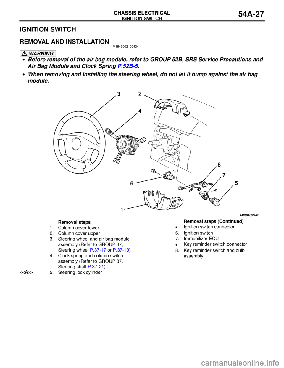
IGNITION SWITCH
CHASSIS ELECTRICAL54A-27
IGNITION SWITCH
REMOVAL AND INSTALLATIONM1543002100434
WARNING
•Before removal of the air bag module, refer to GROUP 52B, SRS Service Precautions and
Air Bag Module and Clock Spring P.52B-5.
•When removing and installing the steering wheel, do not let it bump against the air bag
module.
AC304659
2
3
4
67
15
AB
8
Removal steps
1. Column cover lower
2. Column cover upper
3. Steering wheel and air bag module
assembly (Refer to GROUP 37,
Steering wheel P.37-17 or P.37-19)
4. Clock spring and column switch
assembly (Refer to GROUP 37,
Steering shaft P.37-21)
<>5. Steering lock cylinder•Ignition switch connector
6. Ignition switch
7. Immobilizer-ECU
•Key reminder switch connector
8. Key reminder switch and bulb
assembly Removal steps (Continued)
Page 473 of 788
HAZARD WARNING LAMP SWITCH
CHASSIS ELECTRICAL54A-85
HAZARD WARNING LAMP SWITCH
TROUBLESHOOTING
M1542000701333
FLASHER TIMER FUNCTION
The hazard warning lamps (flasher timer function)
are controlled by the Smart Wiring System (SWS).
For troubleshooting, refer to respective Groups
below.•Not using SWS monitor: GROUP 54B, SWS
Troubleshooting P.54B-38.
•Using SWS monitor: GROUP 54C, SWS
Troubleshooting P.54C-22.
SPECIAL TOOL
M1542000600935
AC304717AB
2
1 3 4
56
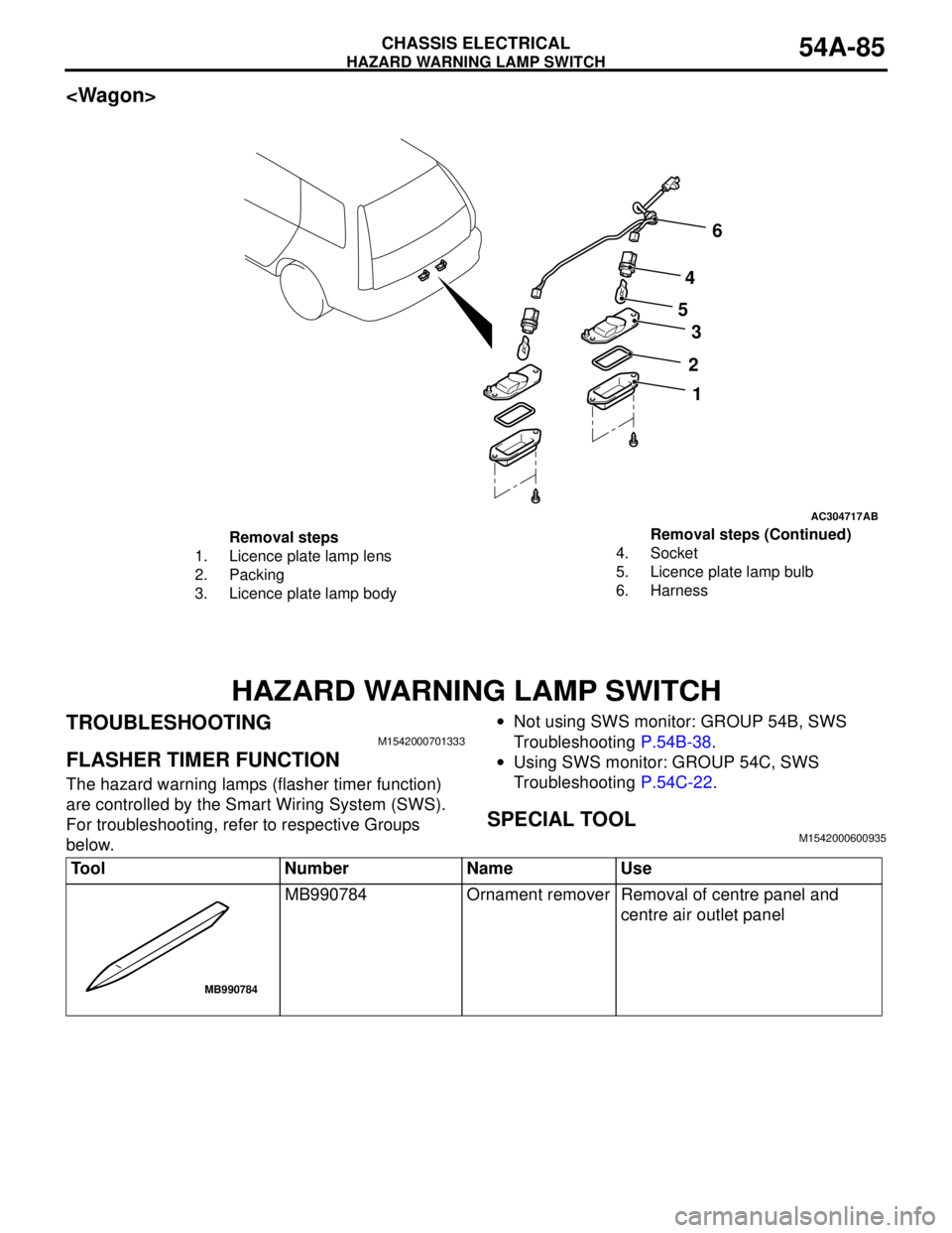
Removal steps
1. Licence plate lamp lens
2. Packing
3. Licence plate lamp body4. Socket
5. Licence plate lamp bulb
6. HarnessRemoval steps (Continued)
Tool Number Name Use
MB990784 Ornament remover Removal of centre panel and
centre air outlet panel
MB990784
Page 474 of 788
HAZARD WARNING LAMP SWITCH
CHASSIS ELECTRICAL54A-86
HAZARD WARNING LAMP SWITCH
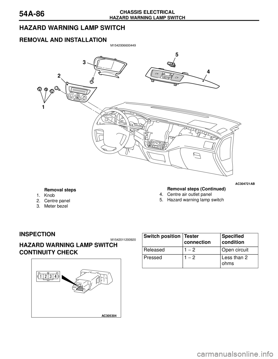
REMOVAL AND INSTALLATIONM1542006600449
INSPECTIONM1542011200920
HAZARD WARNING LAMP SWITCH
CONTINUITY CHECK
AC304721AB
3
4
2
15
Removal steps
1. Knob
2. Centre panel
3. Meter bezel4. Centre air outlet panel
5. Hazard warning lamp switchRemoval steps (Continued)
AC305304
Switch position Tester
connectionSpecified
condition
Released 1 − 2 Open circuit
Pressed 1 − 2 Less than 2
ohms
Page 485 of 788
55-1
GROUP 55
HEATER, AIR
CONDITIONER AND
VENTILATION
CONTENTS
SERVICE SPECIFICATIONS . . . . . . .55-3
LUBRICANTS . . . . . . . . . . . . . . . . . .55-3
SPECIAL TOOLS . . . . . . . . . . . . . . . .55-4
TROUBLESHOOTING . . . . . . . . . . . .55-5DIAGNOSIS TROUBLESHOOTING
FLOW . . . . . . . . . . . . . . . . . . . . . . . . . . . . . 55-5
SYMPTOM CHART . . . . . . . . . . . . . . . . . . . 55-5
SYMPTOM PROCEDURES . . . . . . . . . . . . 55-5
CHECK AT ECU TERMINAL
CHECK AT ECU TERMINAL
Continued on next page
W ARNING S RE GA RDING S E RV ICIN G O F SUP P LE MEN TAL R ES TRAI NT S Y ST EM (SRS ) E Q UIP PE D VE HICL ES
I mp roper se rvi ce o r m ai nte na nce of a ny c omp onent of the SRS , or an y SRS -re la te d c om pone nt, ca n le a d to
personal injury or death to service personnel (from inadvertent firing of the air bag) or to the driver (from
re nd er ing the S RS inop er ati ve).
S e rvic e or m ai nten anc e of an y SRS com pon ent or SRS -re late d com pone nt m ust be pe rfor me d only a t an
authorized MITSUBISHI dealer.
M ITSUBISHI dealer p erso nnel must thoroughly review th is man ual, and esp ecially its GROU P 52B - Su pplemen tal
Restraint System (SR S) b efore beginn ing an y service o r maintenance of any comp onent of th e SRS or any SRS-
rel ated com ponent.
NOTE
The SRS includes the following components: front impact sens ors , SRS-ECU, SRS warning lamp, air bag module, c lock spring
and interconnecting wiring. Other SRS-related components (that may have to be remov ed/installed in connection with SRS
service or maintenance) are indicated in the table of c ontents by an asterisk (*).
Page 623 of 788
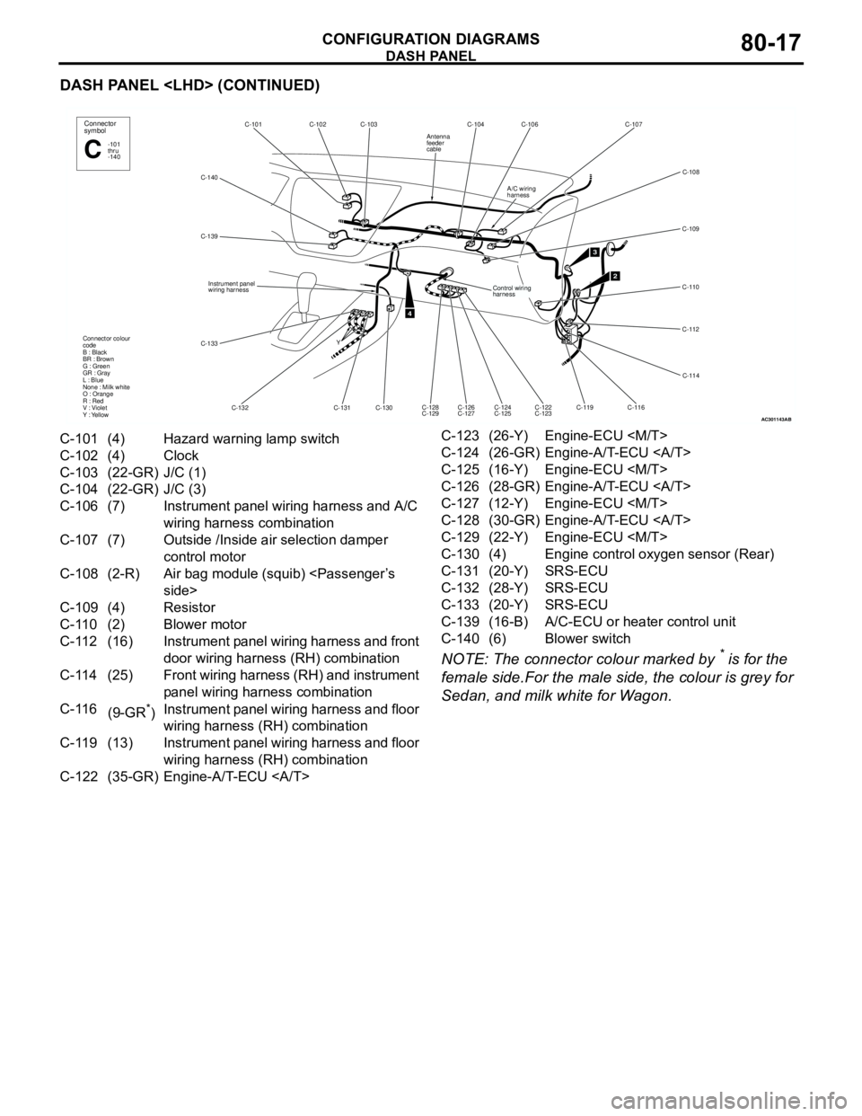
DASH PANEL
CONFIGURATION DIAGRAMS80-17
DASH PANEL
NOTE: The connector colour marked by
* is for the
female side.For the male side, the colour is grey for
Sedan, and milk white for Wagon.
AC301143
C-140C-102C-103 C-101
C-132 C-139
C-130 Y
4
Connector
symbol
-101
thru
-140C
Connector colour
code
B : Black
BR : Brown
G : Green
GR : Gray
L : Blue
None : Milk white
O : Orange
R : Red
V : Violet
Y : Yellow
Instrument panel
wiring harness
C-131
C-133
AB
C-104 C-106 C-107
C-109
C-110
C-112
C-114
C-116
C-119 C-126
C-127 C-128
C-129
2
C-108
C-124
C-125C-122
C-123
3
Control wiring
harness
A/C wiring
harness
Antenna
feeder
cable
C-101 (4) Hazard warning lamp switch
C-102 (4) Clock
C-103 (22-GR) J/C (1)
C-104 (22-GR) J/C (3)
C-106 (7) Instrument panel wiring harness and A/C
wiring harness combination
C-107 (7) Outside /Inside air selection damper
control motor
C-108 (2-R) Air bag module (squib)
C-109 (4) Resistor
C-110 (2) Blower motor
C-112 (16) Instrument panel wiring harness and front
door wiring harness (RH) combination
C-114 (25) Front wiring harness (RH) and instrument
panel wiring harness combination
C-116
(9-GR
*)Instrument panel wiring harness and floor
wiring harness (RH) combination
C-119 (13) Instrument panel wiring harness and floor
wiring harness (RH) combination
C-122 (35-GR) Engine-A/T-ECU C-123 (26-Y) Engine-ECU
C-124 (26-GR) Engine-A/T-ECU
C-125 (16-Y) Engine-ECU
C-126 (28-GR) Engine-A/T-ECU
C-127 (12-Y) Engine-ECU
C-128 (30-GR) Engine-A/T-ECU
C-129 (22-Y) Engine-ECU
C-130 (4) Engine control oxygen sensor (Rear)
C-131 (20-Y) SRS-ECU
C-132 (28-Y) SRS-ECU
C-133 (20-Y) SRS-ECU
C-139 (16-B) A/C-ECU or heater control unit
C-140 (6) Blower switch